Elesa DD51-E User manual

DD51-E (GN 9054)*
DD51-E-RF
Electronic digital position indicator
OPERATING INSTRUCTIONS
*(Product series valid only for Germany)

2
EN
DD51-E - DD51-E-RF
Models all rights reserved in accordance with the law. Always mention
the source when reproducing our drawings and photos.
Electronic digital position indicator
Contents
1. Safety Instructions 4
1.1 Product release information 5
2. Description 6
2.1 Version - DD51-E-RF 7
3. Installation 7
4. Display 8
5. Key functions 8
6. Switching on/off the device 11
6.1 Switching on the device 11
6.2 Switching off the device (for storage only)12
7. Operating mode 12
7.1 Reference points, origin and offset 12
7.2 Resolution 13
7.3 Absolute or relative measure selection13
7.4 Unit of measure selection 14
7.5 Reference point setting 14
7.6 Direct programming of Origin, Offset and
Step parameters 15
7.7 Targets 16
7.7.1 Programming the targets 16
7.7.2 Load a target 16
7.7.3 Indications for reaching the target
position 16
7.7.4 Disabling the target 17
7.7.5 Display in target mode 17
7.8. Version - DD51-E-RF 18

3
DD51-E - DD51-E-RF
EN
Models all rights reserved in accordance with the law. Always mention
the source when reproducing our drawings and photos.
Electronic digital position indicator
7.8.1 Programming the Net ID and Net
CH parameters 18
7.8.2 Targets 19
8. Programming mode 19
8.1 Input of numeric parameters 19
8.2 Programmable parameters (in
alphabetical order) 20
8.3 Main menu tree 23
8.4 Target menu tree 25
8.5 Additional functions 25
8.5.1 Reset 25
8.5.3 LCD test 25
8.5.4 Device version 26
8.5.5 Password 26
9. Battery replacement 26
10. Display messages and troubleshooting 27

4
EN
DD51-E - DD51-E-RF
Models all rights reserved in accordance with the law. Always mention
the source when reproducing our drawings and photos.
Electronic digital position indicator
1. Safety Instructions
The product has been designed and manufactured in
accordance with the current regulations. The product
leaves the factory ready for use and complies with the
safety standards. To maintain the product in this state, it
is necessary that it is assembled and used properly, in the
closest compliance with this instructions manual and with
the following specific safety precautions.
Before installing and using the DD51-E, read carefully this
manual, which is intended as an indispensable supplement
to the existing documentation (catalogues, data sheets).
Morever, all the rules of law must be observed, in regard to
accident prevention and environmental protection.
The use, without complying with the
descriptions / specific parameters, (in
combination with systems / machines /
processes to be controlled), can lead to a
malfunction of the product, causing:
- health hazards,
- environmental hazards,
- damage to the product and to its proper functionality.
The device must not be used:
- in explosion hazard areas;
- in medical / life support areas and equipment.
Do not open the equipment and do not make any
modifications! Modification of the equipment could
adversely affect the reliability of the device and could
lead to hazards! Do not attempt any repairs. Always return
any defective equipment to the manufacturer! Any breach
of the integrity of the device as delivered will invalidate
the warranty.
Setup/Commissioning
In the event of abnormal behaviour (including change
of operating conditions), the device must be shut down

5
DD51-E - DD51-E-RF
EN
Models all rights reserved in accordance with the law. Always mention
the source when reproducing our drawings and photos.
Electronic digital position indicator
immediately. Installation and commissioning must only
be carried out by adequately trained and authorised
personnel. After correct assembly and commissioning,
the device is ready for operation.
Maintenance/repair
Switch off the power supply to the equipment before
carrying out any operation. Maintenance must be
performed only by trained and authorised persons.
Do not open or modify the indicator case. Tampering
with this product can compromise the correctness and
accuracy of its function.
In the event of a malfunction, do not attempt to repair the
unit and contact the Elesa sales office.
1.1 Product release information
Although almost all features are the same as in previous
releases, this manual specifically refers to devices
updated to firmware revision 6.0 or later.
NOTE: This equipment has been tested and found
to comply with the limits for a Class A digital device,
pursuant to part 15 of the FCC Rules. These limits are
designed to provide reasonable protection against
harmful interference when the equipment is operating in a
commercial environment. This equipment generates, uses,
and can radiate radio frequency energy: if not installed
and used in accordance with the instructions manual, it
may cause harmful interference to radio communications.
Operation of this equipment in a residential area is likely
to cause harmful interference in which case the user will
be required to correct the interference at his own expense.

6
EN
DD51-E - DD51-E-RF
Models all rights reserved in accordance with the law. Always mention
the source when reproducing our drawings and photos.
Electronic digital position indicator
2. Description
The DD51-E position indicators, with battery power supply,
can be used, mounted on pass-through shafts, to provide
the reading of the absolute or relative positioning of a
machine component.
Caratteristiche Meccaniche - Elettriche
Power supply Lithium battery CR2450 3.0 V
Battery life Up to 5 years
(3 years for RF version)
Display 5-digit LCD of 8 mm height
and special characters
Reading scale -19999; 99999
Number of decimal digits programmable
Unit of measure mm, inches, degrees
programmable
Rotation max. speed 300/600/1000 r.p.m. (2)
programmable
Precision 10.000 impulses/revolution
Protection level IP65 or IP67
Working temperature 0 °C ÷ +50 °C
Storage temperature -20 °C ÷ +60 °C
Relative humidity max. 95% a 25 °C
without condensation
Environment indoor use
Interference protection Complies with Directive
2014/53/EU (RED).
Conditions of use For use in closed and
sheltered places only
Altitude up to 2000 m
(2) Default: 600 r.p.m.
A rotation speed higher than 600 rpm can only be
maintained for short periods of time.
The maximum speed value affects the battery life.
7
DD51-E - DD51-E-RF
EN
Models all rights reserved in accordance with the law. Always mention
the source when reproducing our drawings and photos.
Electronic digital position indicator
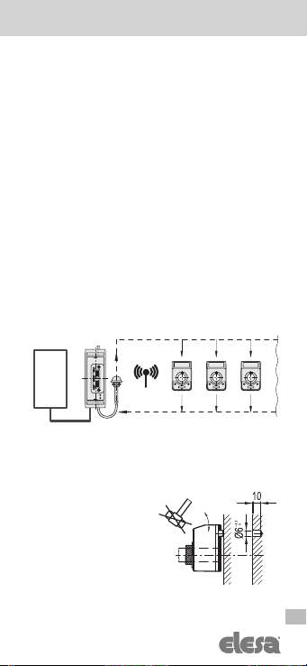
2.1 Version – DD51-E-RF
The DD51-E-RF is compatible with Elesa wireless
network which allows meters and electronic indicators to
communicate via radio with a PLC.
Elesa wireless network is made by the following components:
- One control unit UC-RF
- Max 36 device as DD51-E-RF, DD52R-E-RF or MPI-R10-RF
The UC-RF exchanges information with the DD51-E-RF
via radio frequency and makes it possible to set the target
position and check the current position of each indicator.
Through an interface, available for the most common
industrial buses (ProfiNet, Ethernet/IP, Modbus/TCP, and
others), the UC-RF control unit allows the exchange of this
information with a PLC and/or a generic controller of the
machine.
3. Installation
1.Drill a Ø 6x10 mm hole in the machine body with a 22
mm centre distance from the shaft for mounting the rear
reference pin.
2. Mount the indicator on
the shaft and make sure the
reference pin fits into the
hole.
3. Lock the bushing on the
shaft by tightening the grub
screw with a 2.5mm hexagon
socket (as per UNI 5929-85).
Target positions
Current positions
PLC
8
EN
DD51-E - DD51-E-RF
Models all rights reserved in accordance with the law. Always mention
the source when reproducing our drawings and photos.
Electronic digital position indicator
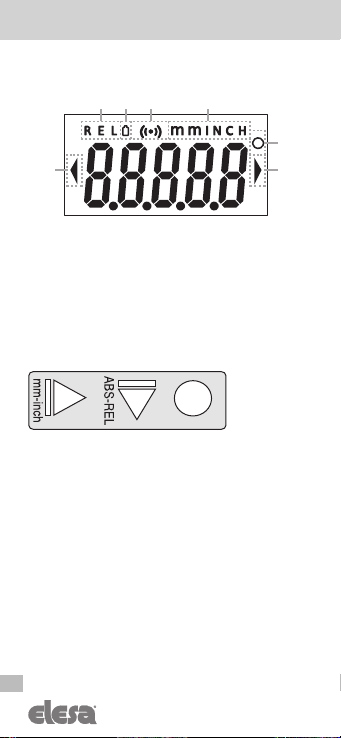
4. Display
1. Relative mode indicator
2. Low battery level indicator
3. Connection indicator (only for DD51-E-RF)
4. Unit of measure: mm, inch
5. Unit of measure: degrees
6. Target position indications
5. Key functions
123
5
4
66
9
DD51-E - DD51-E-RF
EN
Models all rights reserved in accordance with the law. Always mention
the source when reproducing our drawings and photos.
Electronic digital position indicator
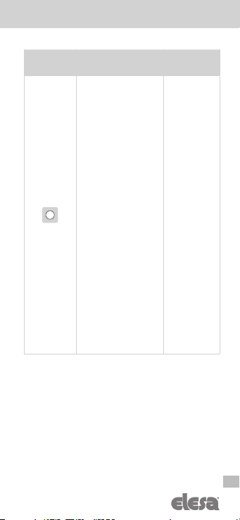
Key Or Key
Combination
Operating
Mode
Programming
Mode
Keeping the key pressed
down for 3s activate
programming mode.
When in target mode, it
reacts to a short press
according to the setting
of item _ _ _ _ 0 of the
main menu (chap. 8.3):
d_tArG
: When
a target is loaded,
the display shows
the current absolute
position. By pressing
the key, the position of
the destination to be
reached appears on the
display.
d_toGO
[DEFAULT]:
when a target is loaded,
the display flashes the
distance from the current
position to the target
position to be reached.
By pressing the key, the
current absolute position
will appear on the display.
OFF
: the function is
disabled.
Select the item
menu or
confirm
selection or
insertion
of the
parameter
value

10
EN
DD51-E - DD51-E-RF
Models all rights reserved in accordance with the law. Always mention
the source when reproducing our drawings and photos.
Electronic digital position indicator
Select the measure
mode:
ABS
: absolute measure
mode
REL
: relative measure
mode
It is possible to choose
one of the following op-
tions (see item _ _ O _ _
of the menu - chap.8.3):
ArCLr
[DEFAULT]:
when changing from
ABS to
REL
the
counter is reset.
Ar
: when changing from
ABS
to
REL
the counter
is not reset.
OFF
: the function is
disabled.
Digit increase
selected /
exit
Unit of measure selection.
The available options are:
millimetres, inches and
degrees.
It is possible to choose
one of the following op-
tions (see item _ _ _ _ 0
of the menu - chap.8.3):
ALL
[DEFAULT]: se-
lectable units of measure:
mm, inch, degrees
nodEG
: selectable units
of measure: mm, inch
OFF
: the function is
disabled
Scroll down
the list of
possible
selections
or menu
items / select
the next digit

11
DD51-E - DD51-E-RF
EN
Models all rights reserved in accordance with the law. Always mention
the source when reproducing our drawings and photos.
Electronic digital position indicator
+
Programmable for one
of the following functions
(see menu item 0 _ _ _ _
0 – chap.8.3):
P_OrG
[DEFAULT]:
shows and allows
you to set the
OriGin
parameter.
P_StP
: shows and
allows you to set the
StEP
parameters.
P_OFS
: shows and
allows you to set the
OFFS
parameters.
OFF
: the combination is
disabled.
N/A
+
In relative measure mode,
resets the measure.
In absolute measure mode
it is programmable for one
of the following functions
(see menu item _0 _ 0 –
chap.8.3):
L_OFS
[DEFAULT]:
select one of the offsets
and set the measure
using it together with the
Origin parameter (see
chap.7.5).
OFF
: the combination is
disabled.
N/A
6. Switching on/off the device
6.1 Switching on the device
After reading and understanding the “Safety Instructions”
section, proceed by switching on the indicator.
To switch on the indicator, hold down while pressing
the key .
The display will switch on and the indicator will be ready
for use.

12
EN
DD51-E - DD51-E-RF
Models all rights reserved in accordance with the law. Always mention
the source when reproducing our drawings and photos.
Electronic digital position indicator
6.2 Switching off the device (for storage only)
To switch the system off:
- select the
rESEt
item from the main menu (see chap.8.3)
- using the key , scroll through the items to select OFF.
- press the key to confirm. The display will switch
off and the indicator will go into sleep mode.
7. Operational mode
7.1 Reference points, origin and offset
When the device is turned on or reset, the position of the
shaft at that moment is set as the origin of the measure.
The value attributed to this position is given by the
parameters, Origin and Offset, which can be set by the
user. Origin is an arbitrary number that can be set in the
range -19999 ÷ 99999 depending on the resolution set
and is to be considered as the machine’s limit switch value
in its default conditions.The offset is added to Origin which
is always an arbitrary value that can be set in the range
-19999 ÷ 99999 depending on the resolution and which
allows you to move the actual origin of the measure based
on any changes in the machine configuration.
For example, a certain set point can operate different
tools with relative displacements of the point of origin.
For example, in the case of a tube cutting machine the
device indicates the position of the stop that determines
the length of the tube. The limit switch point is fixed but it
does not necessarily correspond to a zero length of the
tube and therefore Origin will be different from zero but
always the same.
However, the machine makes it possible to mount different
blades depending on the type of tube and these can have
different positions and/or thicknesses.Therefore the actual
length will have to be corrected with a determined value
which will be memorised as an offset.

13
DD51-E - DD51-E-RF
EN
Models all rights reserved in accordance with the law. Always mention
the source when reproducing our drawings and photos.
Electronic digital position indicator
For greater flexibility of use, the DD51-E permits storage
of up to 10 different offset values.
To program the offset values see the OFFS parameter
in chap. 8.2 However, during installation and for other
specific applications, it is useful to be able to reset the
internal reference value in another position. For this
purpose, see chap. 8.5.1.
WARNING:The value of the Origin parameters and the
offsets are the same for the mm and inch units of measure
and are displayed, depending on the unit of measure
in use (see chap. 7.4), with the appropriate conversion
coefficient.In the case of degrees, these parameters are
totally different and independent from the previous ones.
7.2 Resolution
The device manages different measure display resolution
values for each of the three units of measure managed
(mm, inch and degrees). The same display resolution set
is used to set different parameters such as Origin, offsets
and targets.
WARNING: If the resolution of one of the units of measure
is changed, to avoid setting errors, all the parameters that
are affected are reset: Origin, offset, etc.: It is therefore
advisable to decide and set the display resolution of all
units of measure as a first step in installing the device.
To make the most of the device's measure capacity, the
resolution is automatically reduced if the measure to
be displayed exceeds the capacity of the display. The
measure on the display will flash.
In this case, the resolution variation is temporary (it is
restored if the display is able to display the measurement
with the set resolution) and has no effect on the set
parameters.
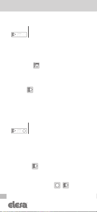
7.3 Absolute or relative measure selection
Press the key to select the absolute or relative
measure mode. The relative measure mode is indicated
on the display by the
REL
symbol. In the case of
14
EN
DD51-E - DD51-E-RF
Models all rights reserved in accordance with the law. Always mention
the source when reproducing our drawings and photos.
Electronic digital position indicator
absolute measure mode, no symbol appears.
0____
It is possible to change the function of
the key by choosing one of the options
available in the menu item _ _ 0 _ _
The available options are:
-
ALL
(default): when changing from
ABS
to
REL
the
counter is reset.
-
nodEG
: when changing from
ABS
to
REL
the counter
is not reset.
-
OFF
:the key is disabled and it is not permitted
to change the measure mode.
7.4 Unit of measure selection
Press the key to select the required unit of measure.
The available options are millimetres, inches and degrees.
The selected measure mode is indicated on the display
by the symbols:
-
mm
: millimeters -
INCH
: inches -
D
: degrees
0___0
It is possible to change the function of
the key by choosing one of the options
available in the menu item. 0_ _ _ _
The available options are:
-
ALL
(default): selectable units of measure: mm, inches
and degrees.
-
nodEG
: selectable units of measure: mm, inch
-
OFF
: the key is disabled and it is not permitted
to change the selected measure mode.
7.5 Reference point setting
By pressing the key combination +it is possible
to reset the measure references of the device by loading

15
DD51-E - DD51-E-RF
EN
Models all rights reserved in accordance with the law. Always mention
the source when reproducing our drawings and photos.
Electronic digital position indicator
the origin value and an offset value (see chap. 7.1).
By pressing the key combination + the screen
will show the last offset value used (e.g
OFS 0
). It is
possible to select the desired offset value by pressing the
key and then confirm by pressing the key .
0____
It is possible to change the function of
the key combination by choosing one
of the options available in the menu
item _ _0 _ 0
The available options are:
-
P_OFS
: the key combination allows you to select an
offset and set the origin value.
-
OFF
: the key combination +is disabled.
WARNING:This function is available only in absolute
measure mode.
7.6 Direct programming of Origin, Offset and
Step parameters
The key combination +
allows direct access to
the programming of one of the following parameter:
Origin, Offset or Step.
0___0
It is possible to change the function of
the key combination by choosing one
of the options available in the menu
item 0 _ _ _ 0.
The available options are:
-
P_OrG
: direct programming of the absolute
reference value (Origin parameter)
-
P_StP
: direct programming of the reading after one
revolution (Step parameter)
-
P_OFS
: direct programming of the offset value (OFFS
parameter)

16
EN
DD51-E - DD51-E-RF
Models all rights reserved in accordance with the law. Always mention
the source when reproducing our drawings and photos.
Electronic digital position indicator
-
OFF
: the key combination +is disabled.
For programming the parameters listed above see
parameter
0___0
of chap. 8.3.
7.7 Targets
The DD51-E allows you to set up to 32 target positions
allowing you to store any relevant and frequently used
settings.
7.7.1 Programming the targets
To program the targets:
- select
tArGE
in the main menu (see chap. 8.3)
- select
PrOGt
(see chap. 8.4)
- select the desired memory location (from
PtG01
to
PtG32
) using the keys and .
- press the key to select.
- follow the instructions in chap. 8.1 to set the desired value.
7.7.2 Load a target:
To load a target:
- select
tArGE
nel menu principale (see chap. 8.3)
- select
LOAdt
(see chap. 8.4)
- select the desired target value (from
LtG01
to
LtG32
)
using the keys and .
- Press the key to select.
- The selected target value is displayed.
- Press again to confirm or press to return to
the target selection list.
7.7.3 Indications for reaching the target position
When a target is selected it is sent by the PLC (RF version
only), the device will suggest the direction of rotation of
the shaft to reach the target through the symbols of

17
DD51-E - DD51-E-RF
EN
Models all rights reserved in accordance with the law. Always mention
the source when reproducing our drawings and photos.
Electronic digital position indicator
the target position indicators.
It is possible to set an acceptable tolerance value for the
targets through the
PtOLL
parameter so that the target
position is considered to have been reached when the
difference between the set target and the current position
is less than
PtOLL
in absolute value.
The target position indicators work, depending on
the,
dir
and
PtOLL
parameters, as in the following
table:
T = target value set
M = actual measure
Toll = tolerance (see
PtOLL
)
dir –o dir o--
M < T - Toll
(blinking) (blinking)
T - Toll ≤ M < T
M = T
T < M ≤ T + Toll
M > T + Toll
(blinking) (blinking)
7.7.4 Disabling the target
If a target is active, it can be cancelled by accessing
programming mode and selecting the
StoPt
option.
7.7.5 Display in target mode
By pressing the key when a target is active, you can
view the current position or the target position depending
on the device settings.
0___0
It is possible to modify the function of
the key and the target mode by selecting
one of the options available in the menu
item _ _ _ _0 (see chap. 8.3)
The available options are:
-
dtArG
(default): when a target is activated, the display

18
EN
DD51-E - DD51-E-RF
Models all rights reserved in accordance with the law. Always mention
the source when reproducing our drawings and photos.
Electronic digital position indicator
shows the actual absolute position and the indication to
reach the target (see chap. 7.7.3).
Pressing the key shows the set target position.
-
dtoGo
: when a target is activated, the display flashes
showing the distance from the set target and the indication
to reach the target (see chap. 7.7.3). When the target is
reached, less than the set tolerance, the display shows the
current position and stops flashing.
Pressing the key ,the display shows the current
absolute position.
7.8 Version - DD51-E-RF
7.8.1 Programming the Net ID and Net CH
parameters
Each RF device is defined within the Elesa wireless
network by the following two parameters:
nEt
id
: this is a number between 0 and 99 and
differentiates different subnets allowing different systems
to work on the same RF channels.
nEt ch
: this is the RF transmission channel and can be
set from 1 to 36. Two or more devices set to the same Net
CH cannot have the same Net ID.
These parameters can be configured in the indicator’s
Radio menu (see chap. 8.2) and must be set according
to the PLC settings to ensure perfect communication with
UC-RF.
WARNING: In pre-existing systems in which a UC-RF with
a firmware release prior to 0F051120 is used (for more
information refer to the UC-RF manual) it is necessary to
take into consideration that the Net CHs are out of phase
by 3 channels. In practice, a DD51-E-RF set with Net CH
= 1 will communicate with UC-RF on CH = 4 and so on for
the following channels.
It will not be possible for DD51-E-RF with firmware revision
6.0 or later to communicate with older generation UC-RF
on channels 1 to 3.
19
DD51-E - DD51-E-RF
EN
Models all rights reserved in accordance with the law. Always mention
the source when reproducing our drawings and photos.
Electronic digital position indicator
7.8.2 Targets
Using the DD51-E-RF, the target positions can be sent
from the PLC to the indicators via the UC-RF control unit.
When a target is transmitted, it behaves in the same way
described in chap. 7.7.
WARNING:If the target transmission on UC-RF is enabled,
it will be refreshed on the DD every time a communication
occurs. Consequently, before disabling the target on the
device (see chap. 7.7.4), disable the target transmission
on UC-RF.
8. Programming mode
Press the key p for 3 seconds to access programming
mode. Depending on the setting of the
PASS
parameter
(see chap. 8.6.4), the system may ask for a password to
be entered. Press the key to scroll through the list of
menu items or parameters and select the desired one by
pressing the key . Press the key to return to the
previous menu level (when allowed) or exit programming
mode. Programming mode is automatically exited after 30
seconds of inactivity.
8.1 Input of numeric parameters
Press the key the selected digit, flashing, increases
in value up to 9 and then returns to 0.
If the first digit on the left is selected and the parameter
can assume negative values, -1 will be displayed after
digit 9 and, by pressing the key again, -.
It is possible to select the digit to be changed by
pressing the key With each press, the digit to the
right of the current one will be selected. If the selected
digit is already at the far right of the display, the selection
will jump to the first digit on the left. Press the key
to confirm the value entered. If the confirmed parameter
is different from the one currently stored, the display will
show the message
CHAnG
.

20
EN
DD51-E - DD51-E-RF
Models all rights reserved in accordance with the law. Always mention
the source when reproducing our drawings and photos.
Electronic digital position indicator
WARNING: It is not possible to cancel the insertion of a
parameter value but only to confirm the displayed one. If
you do not want to change the value already stored, it is
obviously possible to set it to the same value as before
and check that the word
CHAnG
.does not appear. Or,
by waiting 30s, the device will exit programming mode
without saving the changes. The value of any modified
parameters is stored only when exiting the programming
mode. If the operation was successful, the display will
show the messag
StorE
8.2 Programmable parameters (in alphabetical order)
Parameter
Description Available options Default
dir
Direction of
measure.
Sets the
positive
rotation
direction of
the shaft.
--o
anticlockwise
o--
clockwise
--o
diSP
Display
orientation
0°
180°
180°
OFFS
Offset
values
It is possible to store up to
10 offset value:
OFS 0
...
OFS 9
The settable values depend
on the resolution set as
follows:
Res = 1 : -19999 ÷ 99999
Res = 0.1 : -1999.9 ÷ 9999.9
Res = 0.01: -199.99 ÷
999.99
Res =0.001: -19.999 ÷
99.999
0
Other manuals for DD51-E
7
This manual suits for next models
1
Table of contents
Other Elesa Measuring Instrument manuals

Elesa
Elesa DD51-E User manual

Elesa
Elesa MPI-R10 User manual

Elesa
Elesa GN 9054 User manual

Elesa
Elesa DD51-E User manual

Elesa
Elesa DD52R-E-RF User manual

Elesa
Elesa DD52R-E User manual

Elesa
Elesa DD52R-E User manual

Elesa
Elesa MPI-R10 User manual

Elesa
Elesa MPI-15 User manual

Elesa
Elesa DD52R-E User manual


