Eneo MCB-68V2713M0A User manual

EN
User Manual
1/2.8" HD Camera, Day&Night,
3840x2160, Infrared, WDR,
2.7-13.5mm, 12/24V, IP67
MCB-68V2713M0A


Safety Precaution
03
ULTRA CLEAR RESOLUTION CAMERA
CAUTION: TO REDUCE THE RISK OF ELECTRIC SHOCK,
DO NOT REMOVE COVER (OR BACK).
NO USER SERVICEABLE PARTS INSIDE.
REFER SERVICING TO QUALIFIED SERVICE PERSONNEL.
To prevent electric shocks and risk of fire hazards, do NOT use other than
specific power source.
The symbol is intended to alert the user to the presence of important
operating and maintenance(servicing) instructions in the literature
accompanying the unit.
The symbol is intended to alert the user to the presence of uninsulated
"dangerous voltage" within the product's enclosure that may be of
sufficient magnitude to constitute a risk of electric shock to persons.
Warning :
This equipment has been tested and found to comply with the limits for a Class
A digital device, pursuant to part 15 of the FCC Rules. These limits are designed
to provide reasonable protection against harmful interference when the equipment
is operated in a commercial environment. This equipment generates, uses, and
can radiate radio frequency energy and, if not installed and used in accordance with
the instruction manual, may cause harmful interference to radio communications.
Operation of this equipment in a residential area is likely to cause harmful
interference in which case the user will be required to correct the interference at
his own expense.
Caution :
Any changes or modifications in construction of this device which are not expressly
approved by the party responsible for compliance could void the user's authority
to operate the equipment.
Mains power quality should be that of a typical commercial environment. If the user
of the model requires continued operation during power mains interruptions, it is
recommended that the model be powered from an uninterruptible power supply
(UPS) or a battery.

ULTRA CLEAR RESOLUTION CAMERA
Safety Precaution
04
NOTICE
The image used in this instruction manual are processed to help comprehension
and may differ from actual video of the camera.
Avoid installing areas where has shock or vibration which results in the problems.
Pay attention to safety when laying the connection cable and observe that the cable
is not subjected to heavy loads, kinks or damage and no moisture can get in.
The warranty becomes void if repairs are undertaken by unauthorized persons.
Maintenance and repair have to be carried out only by authorized service centers.
Use only a mild detergent to clean the housing.
The camera should never be operated beyond the technical specifications.
This can lead to destruction.
The camera should never be operated in water.

ULTRA CLEAR RESOLUTION CAMERA
Contents
05
Safety Precaution
p.03~04
Contents
p.05
Features
p.06
Composition
p.07
Dimensions
p.07
Part Names
p.08
Installation Instructions
p.09~14
Operating Instructions
p.15~34
Specifications
p.35

ULTRA CLEAR RESOLUTION CAMERA
Features
Key Features
06
• 8Mega Pixel CAMERA, 3840x2160(15/12.5fps)
• The best low light performance with SONY’s STARVIS sensor
• Video output EX-SDI / HD-SDI / THD / CHD / AHD /
CVBS(960H) Selectable
• THD mode / AHD mode / CHD mode,
Video Transmission Distance over Coax.; 500M
• f= 2.7~13.5mm, 8 MP Motorized Zoom lens
• Motorized Zoom & Focus adjustment
• DIS (Digital Image Stabilization) function
• DOL(Digital OverLap) WDR
• ROI (Region of Interest) WDR mode:
- Proper compensation of exposure for each inside and outside
of interested area.
- Better contrast and No motion ghost effect
• Improved Noise figure with the enhanced 3D-NR
• Motion Detection, Privacy Mask, Defog, Sens-up,
D-Zoom, Sharpness, Mirror/Flip, BLC/HLC,
LSC (Lens Shading Compensation)
• OSD Menu for easy installation & maintenance
• Menu control by UTC(THD/AHD) through compatible DVR
• Circuit protection against faulty connection in power polarity
• 4pcs High power SMD LED
• Dual window to prevent from IR reflection
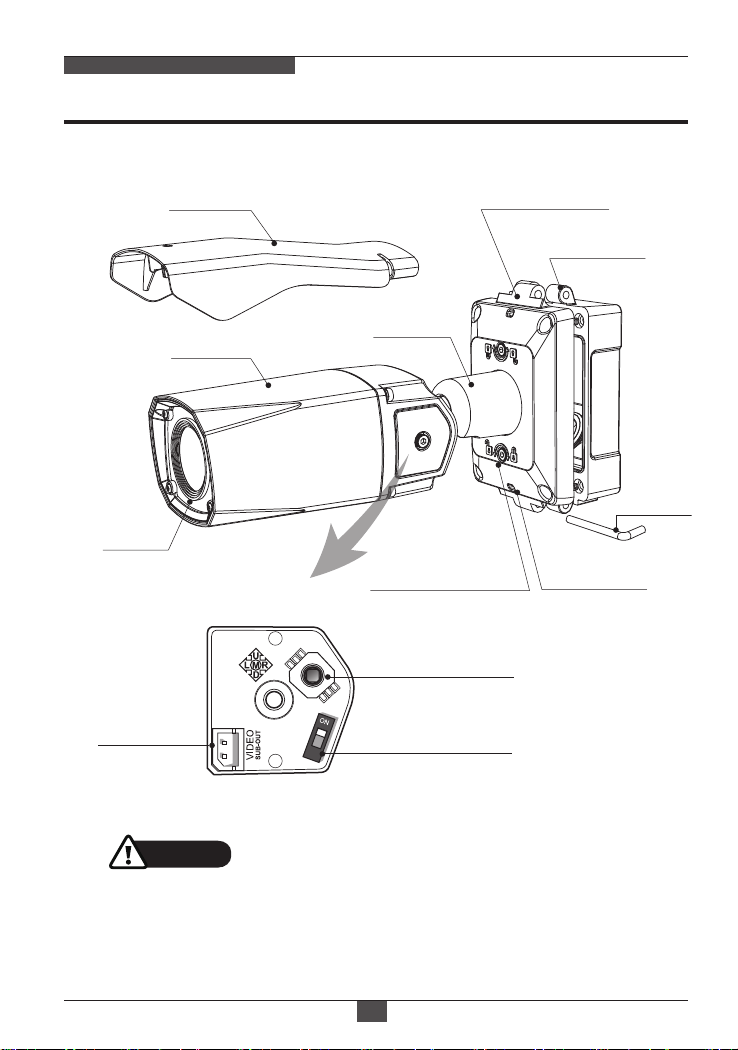
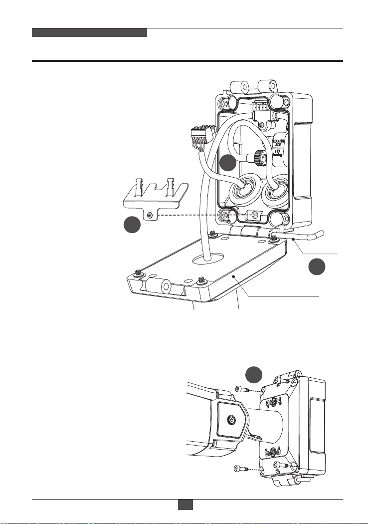
• One-touch 3-Axis locking bracket with Junction Box
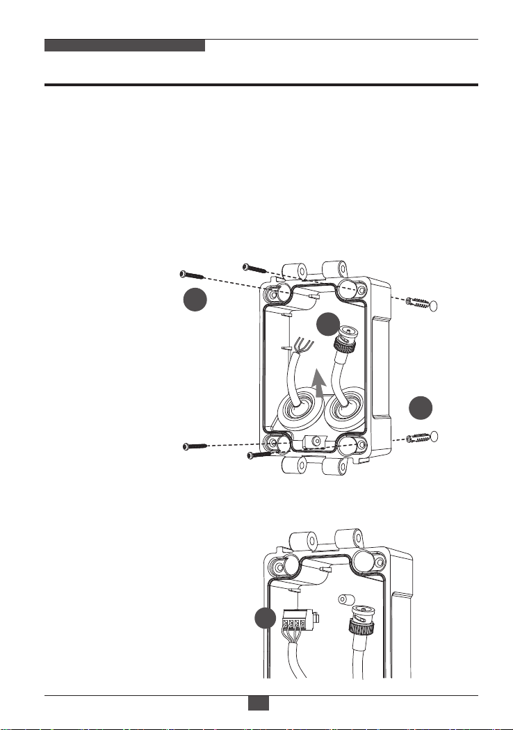
• Integral and Handheld Junction Box
- Simple way to plug BNC & Power connector
- Easy wiring and tidy cable arrangement.
- A handheld Junction Box provides the easiest and most flexible
installation
• IP67 protection
• AC24V/DC12V

07
Composition
ULTRA CLEAR RESOLUTION CAMERA
Dimensions (unit : mm)
Video Sub-out
Cable
Mounting
Template
Operating
Instruction
Hex Wrench:
3mm (1pc)
Camera unit
Sunshield
Mounting Screw:
4 x 30mm (4pcs)
Plastic Anchor:
6 x 30mm (4pcs)
Wiring
Connector
79.18
82.15 265.80
145.90 51.40
31.00
130.50
109.20
79.00
69.10
Cable fixation plate
with Fixing screw
Hinge Pin
(1pc)
Cable Tie
(2pcs)
Grommet (2pcs)

ULTRA CLEAR RESOLUTION CAMERA
Part Names
08
• Extreme care should be taken NOT to
scratch the window in front of lens.
• Care should be taken the cable is NOT
to be damaged, kinked or exposed in
the hazardous area.
• Do not expose the camera directly to a strong light source such as the sun
or spot light.
CAUTION
Dual
Window
Body Case
Sunshield
Bracket
Junction Box TOP
Junction Box
BASE
Inside of Opening Cover
2x Lock/Unlock Screw 2x Water drain
Hinge Pin
Video Sub-out
Connector
OSD Control Joy Stick
Video format Switch

ULTRA CLEAR RESOLUTION CAMERA
Installation Instructions
09
1
3
①Locate the mounting template at the installation position and drill the wall if
needed.
②Route the Power/Video cables through with the Grommets from the wall.
Insert the grommets onto the junction box base.
③Place the Junction box base on pre-drilled position and fix it through using
mounting screws (4x30mm).
Install the mount onto a strong structure such as a concrete or steel beam, etc.
Use the supplied accessories when installing the mount to a structure, make sure
that all the screw parts are metallic.
④Connect the cable wiring with wiring connector.
2
⑤
Fix the cable fixation plate and tie up the cable to it.
4

ULTRA CLEAR RESOLUTION CAMERA
Installation Instructions
10
6
5
8
⑥Hook up the Junction Box Top with
the Junction box base by the hinge
pin.
⑦Connects the Power/Video cables
from camera as illustrated.
Fix the Power/Video cables from
camera to junction box base using
the supplied screw.
Junction Box Top
Hinge Pin
* Caution: If assembly screws are not firmly assembled, it causes water leakage.
⑧Cover the Junction box top and tighten assembly screws. (4pcs)
7

ULTRA CLEAR RESOLUTION CAMERA
Installation Instructions
11
■Adjustment of viewing angle
with a bracket
⑨
Set the camera’s orientation and tighten
the lock/unlock screw using hex wrench.
⑩
If necessary, open the opening cover
and connect the video sub-out cable
for OSD menu setting.
⑪After all the setting, close the opening
cover and tighten with the hex wrench.
Hex
wrench
• Using Grommet :
Tear off the cocks of grommets
properly and pull up the cable so
that sealing can wrap the cable
properly as illustrated. If it doesn’t
wrap the cable properly, it could
cause the water leakage problem.
• Recommended cable
length in the housing :
- BNC CABLE: 180mm~190mm
- Power CABLE: 70mm~80mm
including cable stripping section
total: 70~80mm
total: 180~190mm

ULTRA CLEAR RESOLUTION CAMERA
Installation Instructions
12
Pan & Tilt adjustments
1) Pan limit:
Pan is limited to +/- 90°.
3) Inclination limit
(Horizontal image alignment):
Inclination limited to +/-90° max.
2) Tilt limit:
Tilt is limited to 0°(2°) min ~ 90° max.
for wall(ceiling) installation respectively
with reference to the wall(ceiling) when
the inclination of camera module is 0°,
that is, the image is aligned horizontally.
• Unlock the screw on the camera bracket through using the torque wrench supplied
• Set the camera’s viewing angle then lock the screw on the bracket.
±90°
80° 80°
160°
88°
• on the wall • on the ceiling
90°

ULTRA CLEAR RESOLUTION CAMERA
Installation Instructions
13
Sunshield Assembling
• After all adjustments, assemble the sunsheild with the camera unit as illustrated.
①Cover the sunsheild to the camera unit.
② Slide foward to straight the camera front case.
③Push down the front part of sunshield until clicking sound.
Make sure the sunshield is fixed with camera.

ULTRA CLEAR RESOLUTION CAMERA
Installation Instructions
14
Power Supply connections
Camera can work with either AC24V or DC12V, dual voltage power.
Primary and secondary grounds are completely isolated to avoid the possible
ground-loop problems
HD ANALOG
EX/HD SDI
AC24V/DC12V (RED)
AC24V/GND (BLK)
N/A (ORG)
N/A (GRY)

ULTRA CLEAR RESOLUTION CAMERA
Operating Instructions
15
Description of the Motorized ZOOM&FOCUS* adjustment
1) ▲: Zoom In
2) ▼ : Zoom Out
3) ◄: Focus Near
4) ► : Focus Far
(*) Works only when OSD Menu is inactive.
Setup menu can be accessed and controlled by OSD control joystick on
the side of camera unit. Five commands are available with the joy stick.
The design of OSD could be different according to the Model.
Using OSD controller
Video Sub-out
Connector
OSD Control
Joy Stick
Video format
DIP Switch
Cover Open
Description of the joystick operation
1) SET (●) : Access to the menu or enter the setting.
2) UP/DOWN (▲/▼) : Choose the desired sub-menu and to move the cursor up or down.
3) LEFT/RIGHT (◄/►) : Set up the value of the selected menu.
Used to adjust the desired menu selection and to move the cursor left or right.
4) ‘ ’denotes the long press down straightly for about 2 seconds
EX-SDI↔HD-SDI: The default setting is EX-SDI mode.
Using Video format DIP switch
HD-SDI or EX-SDI is selectable by Video format switch only.
AHD, THD, CHD mode is selectable in the menu only.
(SYSTEM> OUTPUT> ANALOG OUTPUT)

MENU SUB MENU CONFIGURATION
LENS DC
MANUAL
MODE (INDOOOR, OUTDOOR, DEBLUR)
EXPOSURE
BACKLIGHT
BRIGHTNESS NIT
SHUTTER
SENS-UP
AGC
0~20
BRIGHTNESS DAY
0~20
AUTO
MANUAL
(SPEED)
FLICKERLESS
0~10
OFF, x2, x4, x8, x16, x32
1/30(1/25), 1/60(1/50), 1/120(100), 1/250(200),
1/500(400), 1/1000(800), 1/2000(1600),
1/4000(3200), 1/8000(6400), 1/15000
(12800), 1/30000(25600)
ZOOM / FOCUS AF MODE
D&N FILTER
MODE CHANGE
SYNC ON, OFF
ENABLE, DISABLE
ZOOMPUSH, MANUAL
INITIAL ON, OFF
3D-NR OFF, LOW, MIDDLE, HIGH
OFF
HLC LEVEL, COLOR
H/V-POS, H/V-SIZE
BLC
WDR WDR MODE
ROI MODE
WEIGHT
FRAME
OFF, BOX, POLYGON
LOW, MIDDLE, HIGH
DAY & NIGHT EXTERN
AUTO
COLOR
COLOR DN
B&W
SMART IR, ANTI-SAT., DELAY,
IR LED CTL.
SMART IR, ANTI-SAT.,
D>N THRES, N>D THRES, DELAY
SMART IR, ANTI-SAT.
D>N THRES, N>D THRES, DELAY
ULTRA CLEAR RESOLUTION CAMERA
Operating Instructions
16
OSD menu Table
*IR LED CTL is supported in IR LED BULLET camera only.

ULTRA CLEAR RESOLUTION CAMERA
Operating Instructions
17
DIS
SPECIAL
RANGE
FILTER
AUTO-C
OFF, ON 10% ~ 30%
LOW, MIDDLE, HIGH
OFF, HALF, FULL
MIRROR OFF, ON
OFF, ON
FLIP
PRIVACY ZONE NUM, ZONE DISP, H/V-POS,
H/V-SIZE, Y LEVEL, CB/CR LEVEL, TRANS
ZONE NUM, ZONE DISP, POS 0-X/Y,
POS 1-X/Y, POS 2-X/Y, POS 3-X/Y,
Y LEVEL, CB/CR LEVEL, TRANS
BOX
POLYGON
1. 0XD-ZOOM
MOTION OSD
TEXT ALARM
DET WINDOW
SENSITIVITY
ESTIMATE
QUICK ZOOM
OFF, ON
ZOOM SPEED, TRACKING, REPEAT
OFF, ON
OFF, ON
0~10
WINDOW USE, WINDOW ZONE, DET
H/V-POS, DET H/V-SIZE
MOTION
SYSTEM OUTPUT
2160P 15/12.5, 1440P 30/25(CROP),
1440P 15/12.5(only AHD mode),
1080P 30/25, 1080P 60/50(only CVBS, 3G-SDI)
EU(PAL), US(NTSC)
FRAME RATE
TV SYSTEM
SDI
OUTPUT
EX-SDI, HD-SDI
EXIT
LANGUAGE
CAM TITLE
SAVE, CANCEL
FACTORY RESET
ENG, GER, KOR, CHN, CHN(S), JPN
OFF, RIGHT UP, LEFT DOWN
OFF, ON
CONFIRM
OFF, DONE
ANALOG OUTPUT
THD / CVBS-SUB, CVBS,
AHD / CVBS-SUB, CHD / CVBS-SUB
PICT. ADJUST
0~20
0~20
0~10
AUTO, AUTOext, PRESET, MANUAL (C-TEMP, R/B-GAIN)
0.45, 0.5, 0.55, 0.6, 0.65, 0.7, 0.75
OFF, LOW, MIDDLE, HIGH
OFF, ON
OFF, ON MODE, LEVEL
WEIGHT
AWB
GAMMA
D-WDR
DEFOG
COLOR GAIN DAY
SHADING
COLOR GAIN NIT
SHARPNESS

ULTRA CLEAR RESOLUTION CAMERA
Operating Instructions
18
iSupported resolution according to Video format.
DIP Switch (EX-SDI set)
2160P 15 /12.5
THD / CVBS-SUB
[ THD MODE ]
ANALOG OUT
FRAME RATE(NT/PAL)
O
N/A
O
O
1440P 30/25(CROP)
1440P 15/12.5
1080P 30/25
N/A
15P(O) / 12.5P(N/A)
15P(O) / 12.5P(N/A)
15P(O) / 12.5P(N/A)
15P(O) / 12.5P(N/A)
O
O
N/A
O
N/A
O
O
N/A
O
O
O
O
O
O
N/A
O
O
N/A1080P 60/50
AHD / CVBS-SUB
[ AHD MODE ]
CHD / CVBS-SUB
[ CHD MODE ]
CVBS EX-SDI
DIP Switch (HD-SDI set)
2160P 15 /12.5
THD / CVBS-SUB
[ THD MODE ]
ANALOG OUT
FRAME RATE(NT/PAL)
O
N/A
O
O
1440P 30/25(CROP)
1440P 15/12.5
1080P 30/25
N/A
O
O
N/A
O
N/A
O
O
N/A
O
O
O
O
O
N/A
O
O
N/A
N/A
1080P 60/50
AHD / CVBS-SUB
[ AHD MODE ]
CHD / CVBS-SUB
[ CHD MODE ]
CVBS HD-SDI

ULTRA CLEAR RESOLUTION CAMERA
Operating Instructions
19
OSD menu Startup
• EXIT : Enters ‘EXIT’ menu with save current setting or without save.
• RETURN : Returns to the previous menu.
Press the ‘OSD menu SET key’ down to access the setup menu mode.
1. LENS
: DC is for the best image when DC Auto iris Vari-focal lens is installed.
1-1. DC
1-2. MANUAL : MANUAL is for the best image when Fixed lens is installed.
Lens can be selected either DC or MANUAL lens.
It should be selected according to lens type.
- INDOOR: Optimized of indoor environment.
- OUTDOOR: Optimized of outdoor environment.
- DEBLUR: It enables to reduce the blur in a certain indoor environment.
Noise or color rolling can be increased.
• MODE : Selects MODE according to lighting condition.
MENU V0. XX
1. LENS
2. ZOOM/FOCUS
3. EXPOSURE
4. BACKLIGHT
5. DAY&NIGHT
6. PICT. ADJUST
7. DIS
8. SPECIAL
9. SYSTEM
A. EXIT
DC
COLOR DN
ON
OFF
SAVE

ULTRA CLEAR RESOLUTION CAMERA
Operating Instructions
20
2-1. AF MODE
2. ZOOM/FOCUS
• ZOOMPUSH: Focusing works steadily for sharp focusing on the object.
In the case of a Motor driven lens, focusing resumes in about 7~8 seconds
to save the lens lifetime when the focus gets lost.
• MANUAL: Focusing can only be adjusted by ▲,▼ of OSD control joystick.
2-2. MODE CHANGE
2-3. D&N FILTER
MODE CHANGE is activated to set ZOOMPUSH in AF MODE.
It is for locking of the lens control to prevent undesirable operation.
2-4. INITIAL
2. ZOOM/FOCUS
AF MODE Changes to MANUAL automatically
after 3 hrs when MODE CHANGE is ENABLED.
AF MODE
MODE CHANGE
D&N FILTER
INITIAL
RETURN
ZOOMPUSH
ENABLED
SYNC OFF
OFF
• ENABLED : Locks and disables the lens operation after 3 hours.
It is recommended to maintain the working-life of the motorized zoom lens.
• DISABLED : Disables the locking feature allowing lens operation at any time.
• SYNC ON : Focusing is activated whenever ICR filter is changed when
camera switches from Day to Night or Night to Day.
• SYNC OFF : Focusing is not activated even if ICR filter is changed.
Lens initialization is necessary during the installation or the regular operation
to align the position data with the mechanical positions whose lens elements
may move and deviate from its calibrated position by the shock or vibration,
for example, during the transportation. Lens initialization is automatically
executed at power up.
INITIAL starts the lens initialization when pressing the joystick straight down
for about 2 sec. It is strongly necessary to execute LENS INIT in cases below;
- At the final step for the installation.
- When focus becomes out of control by the shock or vibration.
(Available only with AF MODE is ZOOMPUSH)
2. ZOOM/FOCUS
AF MODE
MODE CHANGE
D&N FILTER
INITIAL
RETURN
ZOOMPUSH
NOT USED
SYNC OFF
OFF
This manual suits for next models
1
Table of contents
Other Eneo Camcorder manuals