www.enerdrive.com.au Page 19
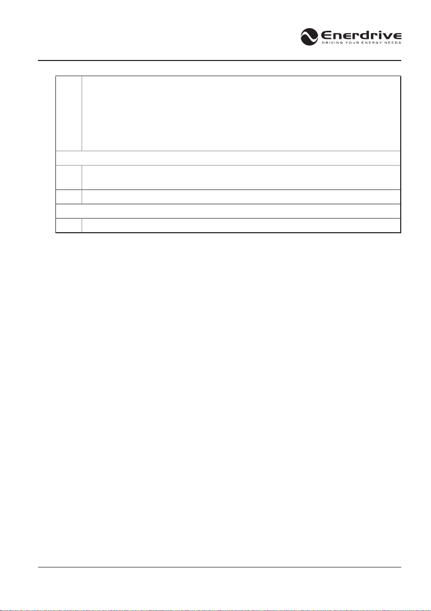
“E01” or “E05” alarm
in By-Pass (pass-
through) mode 2
The unit is normal.
The alarms indicate the battery voltage is low or
the battery is not connected.
Note: There may be external DC loads connect
to the DC input terminals and its drawing current
from the current-limited built-in trickle battery
charger within the inverter. However the unit
continues supplying AC-Output power in despite
of those alarms
Charge and/or connect the battery bank or
disable all the audible alarms with the “AL0”
setting when AC backup is not required.
Note: The main purpose of the internal trickle
battery charger is to keep the unit’s control
electronics working and can still provide AC
Out when utility is available even without the
battery connected. It is not intended to act as
a real trickle charger for your battery bank.
Therefore do not rely on this small trickle charger
as a source to charge your battery bank.
DC voltage is
measured at the DC
terminals without
the battery being
connected (EN1120x,
EN1126X only)
This is normal.
The voltage is supplied by a little built-in trickle
battery charger with current limiting protection.
You can keep the battery disconnected.
However if the DC-Input terminals of the unit
are connected to a common DC bus being shared
by other DC loads, a 12V back feed to those DC
loads can occur when the DC bus is disconnected
from the common battery bank. In this case the
corresponding drawing current may trigger the
“E01” or “E05” alarms as per the problem 2
In cases where the back feed is not desirable,
consider using a separate battery bank
disconnect switch for the unit
The unit’s 10A
thermal breaker trips
even when the unit
is out of an overload
condition
This happens mainly in By-Pass mode when
the maximum rating of the unit’s breaker is
exceeded.
For maximum capacity use the 16A AC-Output
socket which is out of the tripping inuence of
the unit’s 10A thermal breaker. Otherwise do not
exceed 10A on the front AC outlet respectively.
The unit cannot be
turned o using the
power button when in
“By-Pass” mode
This is normal. The unit has “PS1’ (factory
default) setting. Use the procedure on the right
to turn o the unit.
Note: The power button On/O action takes
place at its release moment and after a “beep”
is heard
To turn the unit o while in By-Pass (pass-
through) mode, rst of all disconnect the AC-
Input that feeds the unit to force entering into
Battery (inverter) mode. Then push and hold the
power button for 1 sec. (after hearing a beep)
the unit will turn o.
Set unit to PS4 mode. With this setting, the
power button can be used to turn the unit ON
and OFF during By-Pass and Battery (inverter)
mode.