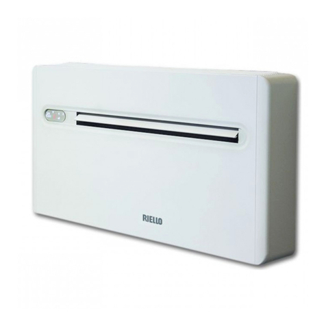
Riello Design white Series User guide

Cod. Doc-0091325 rev. 1 09/2018
HELIOTERM INVERTER
PT INSTRUÇÕES PARA O INSTALADOR E PARA O SERVIÇO DE ASSISTÊNCIA TÉCNICA
EN INSTRUCTIONS FOR THE INSTALLER AND THE TECHNICAL SERVICE CENTRE


HELIOTERM inverter
3
PT
Prezado Cliente,
Obrigado por escolher um produto RIELLO.
Com este manual desejamos oferecer-lhe as informações
que consideramos necessárias para uma instalação
correcta e facilitada, sem termos nada a adicionar às suas
competências e capacidades técnicas.
Renovados agradecimentos.
RIELLO S.p.A.
Conformidade
O aparelho está em conformidade com as seguintes
Normas:
Diretiva de Baixa Tensão 2014/35 UE
Diretiva Compatibilidade Eletromagnética 2014/30 UE e
alterações subsequentes
Diretiva RoHS 2011/65 UE
Gama
Versão Design branco
MODELO CÓDIGO
Design Inverter 11B 20116254
Design Inverter 21B 20116244
Design Inverter 33B 20116246
Design Inverter 40B 20116250
Design Inverter 46B 20116252
Versão Design prata
MODELO CÓDIGO
Design Inverter 11A 20116845
Design Inverter 21A 20116924
Design Inverter 33A 20116925
Design Inverter 40A 20116928
Design Inverter 46A 20116929
Versão Design Plus branco
MODELO CÓDIGO
Design Inverter Plus 11B 20116258
Design Inverter Plus 21B 20116260
Design Inverter Plus 33B 20116261
Design Inverter Plus 40B 20116263
Design Inverter Plus 46B 20116264
EN
Dear Customer,
Thank you for choosing a RIELLO product.
This booklet contains all the information which might be
necessary for the correct and easy installation, without
prejudice for your technical skills and knowledge.
Thanks again.
Riello S.p.A.
Compliance
The unit complies with the following Standards:
Low Voltage Directive 2014/35 UE
Electromagnetic Compatibility Directive 2014/30 UE; as
subsequently amended
RoHS Directive 2011/65 UE
Range
Design white version
MODEL CODE
Design Inverter 11B 20116254
Design Inverter 21B 20116244
Design Inverter 33B 20116246
Design Inverter 40B 20116250
Design Inverter 46B 20116252
Design silver version
MODEL CODE
Design Inverter 11A 20116845
Design Inverter 21A 20116924
Design Inverter 33A 20116925
Design Inverter 40A 20116928
Design Inverter 46A 20116929
Design Plus white version
MODEL CODE
Design Inverter Plus 11B 20116258
Design Inverter Plus 21B 20116260
Design Inverter Plus 33B 20116261
Design Inverter Plus 40B 20116263
Design Inverter Plus 46B 20116264

HELIOTERM inverter
4
PT
Versão Design Plus prata
MODELO CÓDIGO
Design Inverter Plus 11A 20069338
Design Inverter Plus 21A 20069339
Design Inverter Plus 33A 20069340
Design Inverter Plus 29A 20069341
Design Inverter Plus 46A 20069342
Versão Design Small branco
MODELO CÓDIGO
Design Inverter S 6B 20116265
Design Inverter S 11B 20116267
Design Inverter S 17B 20116271
Design Inverter S 23B 20116272
Design Inverter S 32B 20116273
Versão de embutir
MODELO CÓDIGO
IN Inverter 11 20069349
IN Inverter 21 20069370
IN Inverter 33 20069371
IN Inverter 40 20069372
IN Inverter 46 20069373
Versão de embutir Plus
MODELO CÓDIGO
IN Inverter Plus 11 20069374
IN Inverter Plus 21 20069375
IN Inverter Plus 33 20069376
IN Inverter Plus 40 20069377
IN Inverter Plus 46 20069378
EN
Design Plus silver version
MODEL CODE
Design Inverter Plus 11A 20069338
Design Inverter Plus 21A 20069339
Design Inverter Plus 33A 20069340
Design Inverter Plus 29A 20069341
Design Inverter Plus 46A 20069342
Design Small white version
MODEL CODE
Design Inverter S 6B 20116265
Design Inverter S 11B 20116267
Design Inverter S 17B 20116271
Design Inverter S 23B 20116272
Design Inverter S 32B 20116273
Concealed version
MODEL CODE
IN Inverter 11 20069349
IN Inverter 21 20069370
IN Inverter 33 20069371
IN Inverter 40 20069372
IN Inverter 46 20069373
Concealed Plus version
MODEL CODE
IN Inverter Plus 11 20069374
IN Inverter Plus 21 20069375
IN Inverter Plus 33 20069376
IN Inverter Plus 40 20069377
IN Inverter Plus 46 20069378

HELIOTERM inverter
5
PT
Em algumas partes do manual são utilizados os símbolos:
ATENÇÃO = para ações que exigem cautela especial
e preparação adequada.
PROIBIDO = para ações que não devem
absolutamente ser executadas.
ÍNDICE
1. Advertências gerais 6
2. Regras fundamentais de segurança 7
3. Descrição 7
4. Identicação 8
5. Dados técnicos 9
6. Grácosdecaudal-Perdasdecarga 14
7. Dimensões 1 5
8. Esquemas elétricos 16
9. Recepção do produto 22
10. Movimentação e trasporte 22
11. Acesso às partes internas 22
12. Instalação 23
13. Distâncias mínimas de instalação 23
14. Inversão das ligações hidráulicas 24
15. Instalação na parede ou pavimento vertical 26
16. Instalação no teto ou horizontal (apenas Design
Inverter e IN) 27
17. Montagem do suporte de segurança da grelha
dianteira (Design Inverter) 28
18. Ligações hidráulicas 29
19. Descarga de condensados 29
20. Ligações elétricas 31
21. Enchimento da instalação 31
22. Evacuação do ar durante o enchimento da
instalação 32
23. Primeira colocação em serviço 32
24. Manutenção 33
25. Limpeza externa 33
26.Limpezadoltrodeadmissãodoar 33
27. Conselhos de poupança de energia 36
28. Anomalias e soluções 37
29. Tabela das anomalias e das soluções 37
O produto, ao m da vida, não deve
ser descartado como um resíduo sólido
urbano, mas deve ser entregue a um
centro de recolha diferenciada.
At the end of its life, the product should
be not be disposed of as solid urban
waste, but rather it should be handed
over to a differentiated waste collection
centre.
EN
The following symbols are used in this publication:
WARNING = actions requiring special care and
appropriate training.
DO NOT = actions that MUST ON NO ACCOUNT be
carried out.
Index
1. General notices 6
2. Fundamental safety rules 7
3. Description 7
4. Identication 8
5. Technical Data 9
6. ChartsofWaterow-Pressuredrop 14
7. Dimensions 15
8. Electrical diagrams 16
9. Product delivery 22
10. Handling and transportation 22
11. Access to inner parts 22
12. Installation 23
13. Minimum installation distances 23
14. Water connections rotation 24
15. Verticaloororwallinstallation 26
16. Ceiling or horizontal installation (Inverter Design
and IN only) 27
17. Mounting front grill safety support (Design Inverter)28
18. Hydraulic connections 29
19. Condensation discharge 29
20. Electrical connections 31
21. Filling the system 31
22. Evacuationofairwhenllingsystem 32
23. First commissioning 32
24. Maintenance 33
25. Cleaning the outside 33
26.Cleaningairsuctionlter 33
27. Energy saving tips 36
28. Troubleshooting 37
29. Table of anomalies and remedies 37

HELIOTERM inverter
6
PT
1. Advertências Gerais
Após a remoção da embalagem, certique-se de
que o conteúdo está íntegro e completo. Em caso
de necessidade, dirija-se à Agência que vendeu o
aparelho.
A instalação dos aparelhos RIELLO deve ser realizada
porumaempresaqualicadanostermosdalegislação
atualmenteemvigornoPaísque,nonaldotrabalho,
emita ao proprietário a declaração de conformidade da
instalação efetuada de acordo com as boas práticas,
isto é, em conformidade com as normas em vigor e
com as instruções fornecidas nesta publicação.
Estes aparelhos deverão respeitar a destinação de
uso para eles prevista compativelmente com as suas
características de desempenho.
Está excluída qualquer responsabilidade contratual
e extracontratual da RIELLO por danos causados a
pessoas, animais ou bens, por erros de instalação,
regulação, manutenção e por usos impróprios.
Em caso de funcionamento anómalo ou de fugas de
líquidos, coloque o interruptor geral da instalação
em “desligado” e feche as torneiras de intercepção.
Contacte, o mais rapidamente possível, o Serviço
de Assistência Técnica RIELLO. Não intervenha
pessoalmente no aparelho.
Esta publicação deve ser conservada com cuidado por
ser parte integrante do aparelho e deverá acompanhá-
lo SEMPRE, mesmo em caso de transferência para outro
proprietário, utilizador ou instalação. Em caso de
danos ou extravio, solicite outro exemplar ao Serviço
de Assistência Técnica RIELLO local.
As intervenções de reparação ou de manutenção
devem ser efetuadas pelo Serviço de Assistência Técnica
RIELLO ou por pessoal qualicado, tal como previsto
na presente publicação. Não modique, nem adultere
o aparelho, pois, pode criar situações de perigo e o
fabricante do aparelho não será responsável pelos
eventuais danos provocados.
Nas operações de instalação e/o manutenção,
use vestuário e equipamento adequados e contra
acidentes. A empresa fabricante declina qualquer
responsabilidade pelo incumprimento das normas
em vigor em matéria de segurança e prevenção de
acidentes.
Deve-se respeitar as leis em vigor no País no qual a
máquina foi instalada, em relação ao uso e à eliminação
da embalagem, dos produtos utilizados para a limpeza
emanutençãoeparaagestãodonaldavidaútilda
unidade.
EN
1. General notices
Check the integrity and completeness of the supplied
equipment as soon as you take it out of its packaging.
If necessary, consult the Agency that sold you the
equipment.
All RIELLO equipment shall be installed by skilled
operators, in accordance with the laws currently in
force in the country, who shall issue a declaration
of conformity for the state-of-the-art installation,
that is to say, an installation carried out pursuant to
the current Legislation and the instructions in this
booklet.
These units must comply with their intended use,
pursuant to their performance characteristics.
Any contractual and tortious liability of RIELLO’s for
damages to property or people or animals because of
installation, calibration and maintenance mistakes
or erroneous usage of the equipment is excluded.
In case of abnormal operation, or leaks of liquids,
position the main switch of the system in the
“off” position and close the stop taps. Call RIELLO’s
Technical Service or other professionally qualied
personnel immediately. Do not try to repair the unit.
This booklet must be kept carefully as it is an integral
part of the equipment and must ALWAYS be present,
including in case of sale of the equipment to another
owner or user, or of transfer to another system.
Should the manual get damaged or lost, please ask
for a duplicate manual from the RIELLO’s Technical
Service.
Repairs or maintenance actions must be carried out
by RIELLO’s Technical Service staff or other skilled
staff, pursuant to the provisions of this publication.
Do not modify or tamper with this equipment, as
doing so might cause dangerous situation, for which
the manufacturer waives all liability.
In the installation and/or maintenance operations
please adopt the appropriate attire and accident
prevention devices. The Manufacturer waives all and
any responsibility for failure to observe the safety
and accident prevention regulations from time to
time in force.
Comply with the legislation in force on the country of
deployment with regard to the use and disposal of
packaging, of cleaning and maintenance products and
for the management of the unit’s decommissioning.

HELIOTERM inverter
7
PT
2. Regras fundamentais de segurança
3. Descrição
O uso do aparelho é proibido por crianças e pessoas
comdeciênciaquandonãoacompanhadas.
É proibido abrir as portas de acesso e fazer qualquer
intervenção técnica ou limpeza, antes de desconectar o
aparelho da rede de alimentação eléctrica, colocando o
interruptor de alimentação do sistema em "desligado".
É proibido modicar os dispositivos de segurança ou
de regulação sem a autorização e as indicações do
fabricante do aparelho.
É proibido subir com os pés sobre o aparelho, sentar-
se e/ou apoiar no mesmo qualquer tipo de objecto.
É proibido puxar, desligar, torcer os cabos eléctricos
ligados ao aparelho mesmo se este estiver desligado
da rede de alimentação eléctrica.
É proibido borrifar ou deitar água diretamente no
aparelho.
É proibido descartar, abandonar ou deixar ao alcance
de crianças o material da embalagem, sendo este
potencial fonte de perigo.
É expressamente proibido tocar as partes em
movimento, posicionar-se entre elas ou introduzir
objetos pontiagudos através das grelhas.
É proibido tocar no aparelho se estiver descalço e/ou
com partes do corpo molhadas ou húmidas.
O aparelho é um terminal da instalação que contém num só
aparelho a melhor solução para aquecimento, arrefecimento
e desumidicação. Permite atingir eciências energéticas
muito elevadas pela possibilidade de ser acoplado a
geradores de calor de baixa temperatura, tais como: bombas
de calor, caldeiras de condensação, sistemas integrados
com coletores solares. Graças a um sosticado regulador
de temperatura, o aparelho assegura um excelente
conforto térmico em todas as estações. Aquece e arrefece
com extrema rapidez e, uma vez alcançada a temperatura
desejada, mantém-na com uma grande precisão e com o
máximo de silêncio. No aquecimento, o aparelho possui
umecazefeitoconvectivonatural(semelhanteaodeum
radiador), o que reduz consideravelmente a necessidade
de ativar a ventilação. O seu design harmonioso e a
profundidade extraordinariamente reduzida de, apenas, 13
cm fazem com que se adapte a qualquer tipo de ambiente
e mobiliário.
A gama é composta pelos modelos seguintes:
Design Inverter: para instalação à vista
Design Inverter Plus: versão com efeito radiante para
instalação à vista
Design Inverter S: versão rebaixada para instalação à vista
IN: para instalação de embutir na parede ou teto falso
IN Plus: versão com efeito radiante para instalação de
embutir na parede ou teto falso.
As versões para instalação à vista estão disponíveis nas
cores Branco RAL 9003 e Cinza prata. Todos os modelos
são adequados para sistemas de 2 tubos.
As unidade de acoplamento com os vários controlos
a bordo vêm congurados de fábrica com parâmetros
“Comfort”. Para modicar estes parâmetros
(Comfort) em “Performance” é necessário seguir
os procedimentos indicados nas instruções dos
comandos
EN
2. Fundamental safety rules
3. Description
Do not allow children or unassisted disabled people to
use the unit.
Do not open the access covers and carry out technical
or cleaning activities before disconnecting the unit
from the power grid by positioning the system’s main
switch in the “off” position.
It is forbidden to modify the safety or regulation
devices without the authorisation and directions of the
manufacturer.
Do not stand, sit and/or place objects on the unit.
Do not pull, detach or twist the electrical wires coming
out of the unit, even when the unit is disconnected
from the power grid.
Do not spray or throw water directly on the unit.
Do not dispose of, abandon or leave the potentially
hazardous packaging materials within the reach of
children.
It is strictly forbidden to touch any moving parts,
interfere with them or introduce pointed objects
through the grids.
Do not touch the unit while barefoot and/or partially
wet.
The device is a terminal facility that contains in a
single device the best solution for the heating, cooling
and dehumidication. Allows you to achieve energy
efciencyvery highforthepossibilityof beingcoupled
with generators of heat at low temperature such as:
heat pumps, condensing boilers integrated systems with
solar collectors. Thanks to a sophisticated temperature
controller, the device, providing excellent thermal comfort
in every season. Heats and cools very rapidly and once it
reaches the desired temperature, keeps it very precisely
in utter silence. In heating mode, the device develops
an effective natural convective effect (similar to that of a
radiator) which greatly reduces the need to activate the
ventilation. Its harmonious design and exceptionally low
depth of only 13 cm make it integrated into any type of
environment for all furnishing needs.
The range consists of models:
Inverters Design: for positioning at sight
Design Inverter Plus: version with radiant effect for
placement in sight
Inverter Design S: lowered version for placement on
sight
IN: to enter concealed in wall or ceiling
INPlusversionwithradianteffectforinsertioninush
wall or ceiling.
The versions for the positioning at sight are available in
the colors white RAL 9003 and Silver grey. All model are
for 2-pipe system.
The unit combined with different control panels
on board have rhe factory settings with “Comfort”
parameters. To modify from comfort to “Performance”
follow the procedures contained in instructions
supplied with the control panel.
HELIOTERM inverter
8
A
E
H
N
D
B
B
M
L
G
F
A
I
E
D
M
N
Design Inverter - Design Inverter S
IN - IN Plus
Design Inverter Plus
P
PT
4. Identicação
Placa de dados técnicos
A placa de dados técnicos inclui os dados técnicos e de
desempenho do aparelho. Em caso de extravio, solicite
uma segunda via ao Serviço de Assistência Técnica RIELLO.
Caso a Placa de Dados Técnicos não for exposta, for
alterada, retirada, ou se houver algo que impeça a
identicação segura do produto, tornam-se mais
difíceis as operações de instalação e manutenção.
Componentes principais:
A Estrutura de suporte
B Bateria de permuta térmica
D Ventoinha de arrefecimento
E Motor elétrico regulado pelo INVERTER
F Grelha de descarga de ar reversível
G Grelha de admissão de ar
H Reservatório de recolha
I Parte traseira da estrutura
L Revestimento frontal
M Partes laterais removíveis
N Filtro de ar
P Microventilador versão Plus
EN
4. Identication
Technical Tag
The technical tag shows all technical and performance
data of the unit. Should the tag get lost, please ask for
a duplicate tag from the RIELLO’s Technical Service.
Any tampering with, the removal or the lack of the
Technical Tag or of any other element whose absence
preventscertainidenticationoftheproductmakesit
moredifculttoinstallandmaintaintheproduct.
Main components:
A Structure
B Heat exchanger
D Fan unit
E Electric motor controlled by INVERTER
F Supply air grille reversible
G Grille air intake
H Drain pain
I Back structural
L Front cover
M Removable side panels
N Airlter
P Plus version micro-fan

HELIOTERM inverter
9
Design Inverter Plus - IN Inverter Plus - Invisible Inverter Plus
Modelo \ Size 11 21 33 40 46
Desempenho \ Performance
Rendimento total no arrefecimento \ Total cooling capacity a W 1095 2120 3310 3875 4560
Rendimento sensível no arrefecimento \ Sensitive cooling capacity W 855 1610 2595 3090 3675
Caudaldeágua\Waterowrate l/h 188 365 569 667 784
Perdas de carga da água \ Water pressure drop kPa 8,3 9,2 25,2 20,1 27,3
Rendimento no aquecimento com entrada de água a 50 °C \ Heating capacity with
water inlet at 50°C b W 1515 2885 4140 5015 5910
Caudaldeágua(entradadeáguaa50°C)\Waterowrate(waterinletat50°C) l/h 188 365 569 667 784
Perdas de carga da água (entrada de água a 50 °C) \ Water pressure drop (water inlet at 50 °C) kPa 6,6 8,3 22,7 18,0 24,5
Rendimento no aquecimento sem ventilação (50 °C) \ Heating capacity without
ventilation (50 °C) W320 380 460 550 660
Rendimento no aquecimento com entrada água a 70 °C \ Heating capacity with water
inlet at 70°C c W 2590 4855 7035 8445 9990
Caudal de água (70 °C ∆T10)\Waterowrate(70°C∆T 10) l/h 223 418 605 726 859
Perdas de carga da água(70 °C ∆T 10) \ Water pressure drop (70°C ∆T 10) kPa 7,2 8,8 23,4 18,8 25,7
Rendimento no aquecimento sem ventilação (70 °C ∆T 10) \ Heating capacity without
ventilation (70 °C ∆T 10) W540 670 780 920 1080
Características hidráulicas \ Hydraulic features
Teor de água da bateria \ Battery water content litros /
litres 0,47 0,8 1,13 1,46 1,8
Pressão máxima de funcionamento \ Maximum operating pressure bar 10 10 10 10 10
Ligações hidráulicas\ Hydraulic connections polegadas /
inch eurokonus 3/4
Dados aeráulicos \ Aeraulic data
Caudaldear“Performance”\“Performance”airow
d-e
m3/h 197 389 560 699 787
Caudalmáximodear\Maximumairow
d
m3/h 162(*) 320(*) 461(*) 576(*) 648(*)
Caudaldearàvelocidademédia(AUTOmode)\Airowatmediumspeed(AUTOmode) m3/h 113(*) 252(*) 367(*) 453(*) 494(*)
Caudaldearàvelocidademínimadeventilação\Airowatminimumventilationspeed m3/h 55(*) 155(*) 248(*) 370(*) 426(*)
Pressão máxima estática disponível \ Maximum static pressure available Pa 10 10 13 13 13
Dados elétricos \ Electrical data
Tensão de alimentação \ Power supply voltage V/ph/Hz 230/1/50
Potência elétrica máxima absorvida \ Maximum power consumption e W 16,1 25,2 28,4 39 43,3
Corrente máxima absorvida \ Maximum current consumption e A 0,14 0,30 0,32 0,35 0,38
Potência elétrica máxima absorvida \ Maximum power consumption W 12,9 19,6 21,8 29,5 32,7
Corrente máxima absorvida \ Maximum current consumption A 0,11 0,24 0,25 0,26 0,28
Potência elétrica absorvida à velocidade mínima \ Power consumption at minimum
speed W 6 12 14 18 19
Nível sonoro \ SOUND LEVEL
Pressão sonora com o modo “Performance” ativo \ Sound pressure at "Performance"
speed g dB(A) 42,2 43,1 45,5 45,9 47,2
Pressãosonoranocaudalmáximodear\Soundpressureatmaximumairow g dB(A) 39,4 40,2 42,2 42,5 43,9
Pressãosonoranocaudalmédiodear\Soundpressureatmediumairow g dB(A) 33,2 34,1 34,4 35 37,6
Pressãosonoranocaudalmínimodear\Soundpressureatminimumairow g dB(A) 24,2 25,3 25,6 26,3 27,6
Pressão sonora no setpoint da temperatura \ Sound pressure at the set point
temperature g dB(A) 18,8 19,6 22,3 22,7 23,8
PT
5. Dados técnicos
Dados nominais com conguração do comando no
modo “PERFORMANCE“
(a) Temperatura da água à entrada da bateria a 7 °C, temperatura da água
à saída da bateria a 12 °C, temperatura do ar ambiente a 27 °C b.s. e 19
°C b.u. (norma UNI EN 1397)
(b) Temperatura da água à entrada da bateria a 50 °C, caudal de água como
no arrefecimento, temperatura do ar ambiente a 20 °C (norma UNI EN 1397)
(c) Temperatura da água à entrada da bateria a 70 °C, temperatura da
água à saída da bateria a 60°C, temperatura do ar ambiente a 20°C
(d) Caudaldearmedidocomltroslimpos
(e) Se o modo “Performance” estiver ativo
(g) Pressão sonora medida na câmara semianecóica, segundo a norma ISO
7779
* Caudal no arrefecimento. O caudal no aquecimento é (superior a todas
as velocidades) de 20 m³/h para o modelo 11 e de 40 m³/h para os outros
modelos.
EN
5. Technical Data
(a) Heat exchanger inlet water temperature 7 ° C, heat exchanger outlet
water temperature 12 ° C, ambient air temperature 27 ° C d.b. and 19 °
C w.b. (UNI EN 1397)
(b) Heatexchangerinletwatertemperature50°C,waterowrateasin
cooling, ambient air temperature 20 ° C (UNI EN 1397)
(c) Heat exchanger inlet water temperature 70 ° C heat exchanger water
outlet temperature 60 ° C, ambient air temperature 20 ° C
(d) Airowmeasuredwithcleanlters
(e) When “Performance” mode enabled
(g) Sound pressure measured in a semi anechoic chamber according to ISO
7779.
* Coolingcapacity.Theowinheating(greateratallspeeds)20m³/hfor
the 11 model and 40 m³/h for other models.
Nominal dates with the control setting in the
“PERFORMANCE“

HELIOTERM inverter
10
PT
Dados nominais com conguração do comando no
modo “PERFORMANCE“ Nominal dates with the control setting in the
“PERFORMANCE“
Design Inverter - IN Inverter - Invisible Inverter - Inverter de teto invisível
Modelo \ Size 11 21 33 40 46
Desempenho \ Performance
Rendimento total no arrefecimento \ Total cooling capacity a W 1095 2120 3310 3875 4560
Rendimento sensível no arrefecimento \ Sensitive cooling capacity W 855 1610 2595 3090 3675
Caudaldeágua\Waterowrate l/h 188 365 569 667 784
Perdas de carga da água \ Water pressure drop kPa 8,3 9,2 25,2 20,1 27,3
Rendimento no aquecimento com entrada de água a 50 °C \ Heating capacity with
water inlet at 50°C b W 1415 2775 3905 4665 5705
Caudaldeágua(entradadeáguaa50°C)\Waterowrate(waterinletat50°C) l/h 188 365 569 667 784
Perdas de carga da água (entrada de água a 50 °C) \ Water pressure drop (water inlet
at 50 °C) kPa 6,6 7,3 18,3 15,1 20,0
Rendimento no aquecimento com entrada de água a 70 °C \ Heating capacity with
water inlet at 70°C c W 2420 4670 6635 7855 9645
Caudal de água (70 °C ∆T10)\Waterowrate(70°C∆T 10) l/h 208 402 571 676 829
Perdas de carga da água(70 °C ∆T 10) \ Water pressure drop (70°C ∆T 10) kPa 7,5 8,2 17,7 14,8 21,3
Características hidráulicas \ Hydraulic features
Teor de água da bateria \ Battery water content litros /
litres 0,47 0,8 1,13 1,46 1,8
Pressão máxima de funcionamento \ Maximum operating pressure bar 10 10 10 10 10
Ligações hidráulicas \ Hydraulic connections polegadas /
inch eurokonus 3/4
Dados aeráulicos \ Aeraulic data
Caudaldear“Performance”\“Performance”airow
d-e
m3/h 197 389 560 699 787
Caudalmáximodear\Maximumairow
d
m3/h 162 320 461 576 648
Caudaldearàvelocidademédia(AUTOmode)\Airowatmediumspeed(AUTOmode) m3/h 113 252 367 453 494
Caudaldearàvelocidademínimadeventilação \Airowatminimumventilation
speed m3/h 55 155 248 370 426
Pressão máxima estática disponível \ Maximum static pressure available Pa 10 10 13 13 13
Dados elétricos \ Electrical data
Tensão de alimentação \ Power supply voltage V/ph/Hz 230/1/50
Potência elétrica máxima absorvida \ Maximum power consumption e W 15,1 23,2 26,4 36 40,3
Corrente máxima absorvida \ Maximum current consumption e A 0,14 0,32 0,33 0,35 0,38
Potência elétrica máxima absorvida\ Maximum power consumption W 11,9 17,6 19,8 26,5 29,7
Corrente máxima absorvida \ Maximum current consumption A 0,11 0,24 0,25 0,26 0,27
Potência elétrica absorvida à velocidade mínima \ Power consumption at minimum
speed W 6 12 14 18 19
Nível sonoro \ SOUND LEVEL
Pressão sonora com o modo “Performance” ativo \ Sound pressure at "Performance"
speed g dB(A) 42,2 43,1 45,5 45,9 47,2
Pressãosonoranocaudalmáximodear\Soundpressureatmaximumairow g dB(A) 39,4 40,2 42,2 42,5 43,9
Pressãosonoranocaudalmédiodear\Soundpressureatmediumairow g dB(A) 33,2 34,1 34,4 35 37,6
Pressãosonoranocaudalmínimodear\Soundpressureatminimumairow g dB(A) 24,2 25,3 25,6 26,3 27,6
Pressão sonora no setpoint da temperatura \ Sound pressure at the set point
temperature g dB(A) 18,8 19,6 22,3 22,7 23,8
(a) Temperatura da água à entrada da bateria a 7 °C, temperatura da água
à saída da bateria a 12 °C, temperatura do ar ambiente a 27 °C b.s. e 19
°C b.u. (norma UNI EN 1397)
(b) Temperatura da água à entrada da bateria a 50 °C, caudal de água como
no arrefecimento, temperatura do ar ambiente a 20 °C (norma UNI EN 1397)
(c) Temperatura da água à entrada da bateria a 70 °C, temperatura da
água à saída da bateria a 60°C, temperatura do ar ambiente a 20°C
(d) Caudaldearmedidocomltroslimpos
(e) Se o modo “Performance” estiver ativo
(g) Pressão sonora medida na câmara semianecóica, segundo a norma ISO
7779
(a) Heat exchanger inlet water temperature 7 ° C, heat exchanger outlet
water temperature 12 ° C, ambient air temperature 27 ° C d.b. and 19 °
C w.b. (UNI EN 1397)
(b) Heatexchangerinletwatertemperature50°C,waterowrateasin
cooling, ambient air temperature 20 ° C (UNI EN 1397)
(c) Heat exchanger inlet water temperature 70 ° C heat exchanger water
outlet temperature 60 ° C, ambient air temperature 20 ° C
(d) Airowmeasuredwithcleanlters
(e) When “Performance” mode enabled
(g) Sound pressure measured in a semi anechoic chamber according to ISO
7779.
EN

HELIOTERM inverter
11
PT
Dados nominais com conguração do comando no
modo “COMFORT” Nominal dates with the control setting in the
“COMFORT“
EN
Design Inverter Plus - IN Inverter Plus - Invisible Inverter Plus
Modelo \ Size 11 21 33 40 46
Desempenho \ Performance
Rendimento total no arrefecimento \ Total cooling capacity a W 830 1760 2650 3340 3800
Rendimento sensível no arrefecimento \ Sensitive cooling capacity W 620 1270 1960 2650 3010
Caudaldeágua\Waterowrate l/h 143 303 456 574 654
Perdas de carga da água \ Water pressure drop kPa 7,2 8,4 22,5 18,6 24,9
Rendimento no aquecimento com entrada de água a 50 °C \ Heating capacity with
water inlet at 50°C b W 1150 2460 3410 4400 5200
Caudaldeágua(entradadeáguaa50°C)\Waterowrate(waterinletat50°C) l/h 143 303 456 574 654
Perdas de carga da água (entrada de água a 50 °C) \ Water pressure drop (water inlet
at 50 °C) kPa 6,5 7,5 20,2 16,7 22,4
Rendimento no aquecimento sem ventilação (50 °C) \ Heating capacity without
ventilation (50 °C) W320 380 460 550 660
Rendimento no aquecimento com entrada de água a 70 °C \ Heating capacity with
water inlet at 70°C c W 2020 4150 5800 7500 8600
Caudal de água(70 °C ∆T10)\Waterowrate(70°C∆T 10) l/h 174 357 500 645 740
Perdas de carga da água (70 °C ∆T 10) \ Water pressure drop (70°C ∆T 10) kPa 7,2 8,2 21,2 17,7 23,8
Rendimento no aquecimento sem ventilação (70 °C ∆T 10) \ Heating capacity without
ventilation (70 °C ∆T 10) W540 670 780 920 1080
Características hidráulicas \ Hydraulic features
Teor de água da bateria \ Battery water content litros /
litres 0,47 0,8 1,13 1,46 1,8
Pressão máxima de funcionamento \ Maximum operating pressure bar 10 10 10 10 10
Ligações hidráulicas \ Hydraulic connections polegadas /
inch eurokonus 3/4
Dados aeráulicos \ Aeraulic data
Caudalmáximodear\Maximumairow
d
m3/h 162(*) 320(*) 461(*) 576(*) 648(*)
Caudaldearàvelocidademédia(AUTOmode)\Airowatmediumspeed(AUTOmode) m3/h 113(*) 252(*) 367(*) 453(*) 494(*)
Caudaldearàvelocidademínimadeventilação \Airowatminimumventilation
speed m3/h 55(*) 155(*) 248(*) 370(*) 426(*)
Pressão máxima estática disponível \ Maximum static pressure available Pa 10 10 13 13 13
Dados elétricos \ Electrical data
Tensão de alimentação \ Power supply voltage V/ph/Hz 230/1/50
Potência elétrica máxima absorvida\ Maximum power consumption W 12,9 19,6 21,8 29,5 32,7
Corrente máxima absorvida \ Maximum current consumption A 0,11 0,16 0,18 0,26 0,28
Potência elétrica absorvida à velocidade mínima \ Power consumption at minimum
speed W 6 12 14 18 19
Nível sonoro \ SOUND LEVEL
Pressãosonoranocaudalmáximodear\Soundpressureatmaximumairow g dB(A) 39,4 40,2 42,2 42,5 43,9
Pressãosonoranocaudalmédiodear\Soundpressureatmediumairow g dB(A) 33,2 34,1 34,4 35 37,6
Pressãosonoranocaudalmínimodear\Soundpressureatminimumairow g dB(A) 24,2 25,3 25,6 26,3 27,6
Pressão sonora no setpoint da temperatura \ Sound pressure at the set point
temperature g dB(A) 18,8 19,6 22,3 22,7 23,8
(a) Temperatura da água à entrada da bateria a 7 °C, temperatura da água
à saída da bateria a 12 °C, temperatura do ar ambiente a 27 °C b.s. e 19
°C b.u. (norma UNI EN 1397)
(b) Temperatura da água à entrada da bateria a 50 °C, caudal de água
como no arrefecimento, temperatura do ar ambiente a 20 °C (norma
UNI EN 1397)
(c) Temperatura da água à entrada da bateria a 70 °C, temperatura da
água à saída da bateria a 60°C, temperatura do ar ambiente a 20°C
(d) Caudaldearmedidocomltroslimpos
(g) Pressão sonora medida na câmara semianecóica, segundo a norma ISO
7779
* Caudal no arrefecimento. O caudal no aquecimento é (superior a todas
as velocidades) de 20 m³h para o modelo 11 e de 40 m³h para os outros
modelos.
(a) Heat exchanger inlet water temperature 7 ° C, heat exchanger outlet
water temperature 12 ° C, ambient air temperature 27 ° C d.b. and 19 °
C w.b. (UNI EN 1397)
(b) Heatexchangerinletwatertemperature50°C,waterowrateasin
cooling, ambient air temperature 20 ° C (UNI EN 1397)
(c) Heat exchanger inlet water temperature 70 ° C heat exchanger water
outlet temperature 60 ° C, ambient air temperature 20 ° C
(d) Airowmeasuredwithcleanlters
(g) Sound pressure measured in a semi anechoic chamber according to ISO
7779.
* Coolingcapacity.Theowinheating(greateratallspeeds)20m³hfor
the 11 model and 40 m³h for other models.

HELIOTERM inverter
12
PT EN
Dados nominais com conguração do comando no
modo “COMFORT” Nominal dates with the control setting in the
“COMFORT“
Design Inverter - IN Inverter - Invisible Inverter - Inverter de teto invisível
Modelo \ Size 11 21 33 40 46
Desempenho \ Performance
Rendimento total no arrefecimento \ Total cooling capacity a W 830 1760 2650 3340 3800
Rendimento sensível no arrefecimento \ Sensitive cooling capacity W 620 1270 1960 2650 3010
Caudaldeágua\Waterowrate l/h 143 303 456 574 654
Perdas de carga da água \ Water pressure drop kPa 7,2 8,4 22,5 18,6 24,9
Rendimento no aquecimento com entrada de água a 50 °C \ Heating capacity with
water inlet at 50°C b W 1090 2350 3190 4100 4860
Caudaldeágua(entradadeáguaa50°C)\Waterowrate(waterinletat50°C) l/h 143 303 456 574 654
Perdas de carga da água (entrada de água a 50 °C) \ Water pressure drop (water inlet
at 50 °C) kPa 5,7 6,6 16,3 14 18,3
Rendimento no aquecimento com entrada de água a 70 °C \ Heating capacity with
water inlet at 70°C c W 1890 3990 5470 6980 8300
Caudal de água (70 °C ∆T10)\Waterowrate(70°C∆T 10) l/h 162 343 471 600 714
Perdas de carga da água(70 °C ∆T 10) \ Water pressure drop (70°C ∆T 10) kPa 6,7 7,6 16,1 14 19,8
Características hidráulicas \ Hydraulic features
Teor de água da bateria \ Battery water content litros /
litres 0,47 0,8 1,13 1,46 1,8
Pressão máxima de funcionamento \ Maximum operating pressure bar 10 10 10 10 10
Ligações hidráulicas \ Hydraulic connections polegadas /
inch eurokonus 3/4
Dados aeráulicos \ Aeraulic data
Caudalmáximodear\Maximumairow
d
m3/h 162 320 461 576 648
Caudaldearàvelocidademédia(AUTOmode)\Airowatmediumspeed(AUTOmode) m3/h 113 252 367 453 494
Caudal de ar àvelocidade mínima deventilação \ Airow at minimum ventilation
speed m3/h 55 155 248 370 426
Pressão máxima estática disponível \ Maximum static pressure available Pa 10 10 13 13 13
Dados elétricos \ Electrical data
Tensão de alimentação \ Power supply voltage V/ph/Hz 230/1/50
Potência elétrica máxima absorvida\ Maximum power consumption W 11,9 17,6 19,8 26,5 29,7
Corrente máxima absorvida \ Maximum current consumption A 0,11 0,16 0,18 0,26 0,28
Potência elétrica absorvida à velocidade mínima \ Power consumption at minimum
speed W 6 12 14 18 19
Nível sonoro \ SOUND LEVEL
Pressãosonoranocaudalmáximodear\Soundpressureatmaximumairow g dB(A) 39,4 40,2 42,2 42,5 43,9
Pressãosonoranocaudalmédiodear\Soundpressureatmediumairow g dB(A) 33,2 34,1 34,4 35 37,6
Pressãosonoranocaudalmínimodear\Soundpressureatminimumairow g dB(A) 24,2 25,3 25,6 26,3 27,6
Pressão sonora no setpoint da temperatura \ Sound pressure at the set point
temperature g dB(A) 18,8 19,6 22,3 22,7 23,8
(a) Heat exchanger inlet water temperature 7 ° C, heat exchanger outlet
water temperature 12 ° C, ambient air temperature 27 ° C d.b. and 19 °
C w.b. (UNI EN 1397)
(b) Heatexchangerinletwatertemperature50°C,waterowrateasin
cooling, ambient air temperature 20 ° C (UNI EN 1397)
(c) Heat exchanger inlet water temperature 70 ° C heat exchanger water
outlet temperature 60 ° C, ambient air temperature 20 ° C
(d) Airowmeasuredwithcleanlters
(g) Sound pressure measured in a semi anechoic chamber according to ISO
7779.
(a) Temperatura da água à entrada da bateria a 7 °C, temperatura da água
à saída da bateria a 12 °C, temperatura do ar ambiente a 27 °C b.s. e 19
°C b.u. (norma UNI EN 1397)
(b) Temperatura da água à entrada da bateria a 50 °C, caudal de água
como no arrefecimento, temperatura do ar ambiente a 20 °C (norma
UNI EN 1397)
(c) Temperatura da água à entrada da bateria a 70 °C, temperatura da
água à saída da bateria a 60°C, temperatura do ar ambiente a 20°C
(d) Caudaldearmedidocomltroslimpos
(g) Pressão sonora medida na câmara semianecóica, segundo a norma ISO
7779.

HELIOTERM inverter
13
PT EN
Dados nominais com conguração do comando no
modo “COMFORT” Nominal dates with the control setting in the
“COMFORT“
Design S Inverter (SMALL) (f)
Modelo \ Size S6 S11 S17 S23 S32
Desempenho \ Performance
Rendimento total no arrefecimento \ Total cooling capacity a W 560 1040 1640 2310 3140
Rendimento sensível no arrefecimento \ Sensitive cooling capacity W 520 840 1400 2100 2500
Caudaldeágua\Waterowrate l/h 95 179 281 397 539
Perdas de carga da água \ Water pressure drop kPa 4,7 10,7 4,5 2,1 14,5
Rendimento no aquecimento com entrada de água a 50 °C \ Heating capacity with
water inlet at 50°C b W 780 1570 2380 3250 3910
Caudaldeágua(entradadeáguaa50°C))\Waterowrate(waterinletat50°C) l/h 95 179 281 397 539
Perdas de carga da água (entrada de água a 50 °C) \ Water pressure drop (water inlet
at 50 °C) kPa 1,4 8,8 3,4 3,5 13,4
Rendimento no aquecimento com entrada água a 70 °C \ Heating capacity with water
inlet at 70°C c W 1390 2730 4140 5650 6620
Caudal de água(70 °C ∆T10)\Waterowrate(70°C∆T 10) l/h 119 234 356 485 569
Perdas de carga da água(70 °C ∆T 10) \ Water pressure drop (70°C ∆T 10) kPa 213 4,7 4,5 14
Características hidráulicas \ Hydraulic features
Teor de água da bateria\ Battery water content litri /
litres 0,28 0,45 0,61 0,77 0,94
Pressão máxima de funcionamento \ Maximum operating pressure bar 10 10 10 10 10
Ligações hidráulicas \ Hydraulic connections pollici /
inch eurokonus 3/4
Dados aeráulicos \ Aeraulic data
Caudalmáximodear\Maximumairow
d
m3/h 140 250 390 540 600
Caudaldearàvelocidademédia(AUTOmode)\Airowatmediumspeed(AUTOmode) m3/h 96 199 306 416 460
Caudaldearàvelocidademínimadeventilação \Airowatminimumventilation
speed m3/h 49 119 204 343 403
Pressão máxima estática disponível \ Maximum static pressure available Pa 10 10 10 10 10
Dados elétricos \ Electrical data
Tensão de alimentação \ Power supply voltage V/ph/Hz 230/1/50
Potência elétrica máxima absorvida \ Maximum power consumption W 11,9 17,6 19,8 26,5 43
Corrente máxima absorvida \ Maximum current consumption A 0,11 0,16 0,18 0,26 0,27
Potência elétrica absorvida à velocidade mínima \ Power consumption at minimum
speed W 6 12 14 18 19
Nível sonoro \ SOUND LEVEL
Pressãosonoranocaudalmáximodear\Soundpressureatmaximumairow g dB(A) 38,8 39,5 41,4 41,6 42,6
Pressãosonoranocaudalmédiodear\Soundpressureatmediumairow g dB(A) 32,7 33,5 33,7 34,3 36,5
Pressãosonoranocaudalmínimodear\Soundpressureatminimumairow g dB(A) 23,8 24,9 25,1 25,7 26,8
Pressão sonora no setpoint da temperatura \ Sound pressure at the set point
temperature g dB(A) 18,8 19,6 22,3 22,7 23,8
(a) Heat exchanger inlet water temperature 7 ° C, heat exchanger outlet
water temperature 12 ° C, ambient air temperature 27 ° C d.b. and 19 °
C w.b. (UNI EN 1397)
(b) Heatexchangerinletwatertemperature50°C,waterowrateasin
cooling, ambient air temperature 20 ° C (UNI EN 1397)
(c) Heat exchanger inlet water temperature 70 ° C heat exchanger water
outlet temperature 60 ° C, ambient air temperature 20 ° C
(d) Airowmeasuredwithcleanlters
(g) Sound pressure measured in a semi anechoic chamber according to ISO
7779.
(f) The low prole units “SMALL” can only have the control settings
“COMFORT” no “PERFORMANCE”.
(a) Temperatura da água à entrada da bateria a 7 °C, temperatura da água
à saída da bateria a 12 °C, temperatura do ar ambiente a 27 °C b.s. e 19
°C b.u. (norma UNI EN 1397)
(b) Temperatura da água à entrada da bateria a 50 °C, caudal de água
como no arrefecimento, temperatura do ar ambiente a 20 °C (norma
UNI EN 1397)
(c) Temperatura da água à entrada da bateria a 70 °C, temperatura da
água à saída da bateria a 60°C, temperatura do ar ambiente a 20°C
(d) Caudaldearmedidocomltroslimpos
(g) Pressão sonora medida na câmara semianecóica, segundo a norma ISO
7779.
(f) Aunidaderebaixada“SMALL“sópodeteraconguraçãodocomando
no modo “COMFORT“, não no modo “PERFORMANCE“.

HELIOTERM inverter
14
05
06
07
001
09
08
002
051
054
004
053
003
052
009
008
007
006
005
0001
0051
0,5
3,5
3,0
2,5
2,0
1,5
1,0
0,9
0,8
0,7
0,6
8,0
7,0
6,0
5,0
4,5
4,0
15
10
9,0
25
20
0002
3
4
5
1
2
05
06
07
001
09
08
002
051
054
004
053
003
052
009
008
007
006
005
0001
005
1
0,5
3,5
3,0
2,5
2,0
1,5
1,0
0,9
0,8
0,7
0,6
8,0
7,0
6,0
5,0
4,5
4,0
15
10
9,0
25
20
0002
4
51
2
3
Perdita di carico [kPa]
Pressure drop [kPa]
Perdita di carico [kPa]
Pressure drop [kPa]
Portata d’acqua [l/h]
Water flow [l/h]
Portata d’acqua [l/h]
Water flow [l/h]
Perdita di carico [kPa]
Pressure drop [kPa]
Portata d’acqua [kg/h]
Water flow [kg/h]
1
235 4
Perdita di carico [kPa]
Pressure drop [kPa]
Portata d’acqua [kg/h]
Water flow [kg/h]
1
235 4
0,5
1
2
4
8
16
30 150 750
0,5
1
2
4
8
16
30 150 750
Design Inverter, Design Inverter Plus, IN, IN Plus -
Arrefecimento \ Cooling
Design Inverter S - Arrefecimento \ Cooling
Design Inverter, Design Inverter Plus, IN, IN Plus -
Riscaldamento \ Heating
Design Inverter S - Riscaldamento \ Heating
PT
6. Grácos de caudal - Perdas de carga
1 Modelo 11
2 Modelo 21
3 Modelo 33
4 Modelo 40
5 Modelo 46
1 Modelo S 6
2 Modelo S 11
3 Modelo S 17
4 Modelo S 23
5 Modelo S 32
EN
6. Charts of Water ow - Pressure drop
1 Model 11
2 Model 21
3 Model 33
4 Model 40
5 Model 46
1 Model S 6
2 Model S 11
3 Model S 17
4 Model S 23
5 Model S 32

HELIOTERM inverter
15
Modelo \ Size S 6 - 11 S 11 - 21 S 17 - 33 S 23 - 40 S 32 - 46
Dimensões \ Dimensions
A mm 140 140 140 140 140
B mm 80 80 80 80 80
C mm 20 20 20 20 20
D mm 20 20 20 20 20
E mm 400 400 400 400 400
F mm 2500 2500 2500 2500 2500
Dimensões \ Dimensions: Design Inverter - Design Inverter Plus - Design Inverter S
L mm 770 970 1170 1370 1570
Dimensões\ Dimensions: IN - IN Plus
L mm 525 725 925 1125 1325
Peso líquido \ Net weight
Design Inverter / Design Inverter Plus Kg 17 20 23 26 29
Design Inverter S Kg 12 14 16 19 23
IN / IN Plus Kg 912 15 18 21
660
580
L
130
129
459
379
L
Design Inverter - Design Inverter Plus IN - IN Plus
Design Inverter S
126
590
L
16,4 (*)
62 47,2
PT
7. Dimensões
EN
7. Dimensions

HELIOTERM inverter
16
PT
8. Esquemas elétricos
Ligações CBD 35
H2 sonda de temperatura da água 10 kΩ
H4 não disponível
AIR sonda de temperatura do ar 10 kΩ
M1 motor do ventilador DC inverter
S1 microinterruptor de segurança da grelha
Y1 eletroválvula de água (tensão de saída de 230 V/ 50 Hz
1 A)
Y2 ligaçãoapmóvel(tensãodesaídade230V/50Hz1A)
L-N ligação de alimentação elétrica 230 V/50 Hz
BO saída de permissão da caldeira (contacto limpo máx.
1 A)
CH saída de permissão do refrigerador (contacto limpo
máx. 1 A)
CP entrada do sensor de presença (se estiver fechado, o
ventiloconvector é colocado em stand-by.)
RS Cablagem da versão Plus
HRS sonda de água, versão Plus (2kΩ)
Se, após a ligação, a placa detetar a sonda, o
arranque ocorre em condições normais com funções
de temperatura mínima da água no aquecimento (30
°C) e máxima no arrefecimento (20 °C). A placa prevê
também o funcionamento sem sonda, nesse caso, os
limites de mínimo e máximo são ignorados.
H2 water temperature probe 10 kΩ
H4 not avaible
AIR air temperature probe 10kΩ
M1 fan motor DC inverter
S1 grill safety micro-switch
Y1 water solenoid valve (230V/50Hz 1A powered output)
Y2 connectionapmobile(230V/50Hz1Apoweredouyput)
L-N 230V/50Hz electrical power supply connection
BO boiler go-ahead output (free contact max 1A)
CH chiller go-ahead output (free contact max 1A)
CP presence sensor input (if closed, the fan coil goes into
stand-by.)
RS Plus version wiring
HRS Plus version probe (2kΩ)
If after powering the equipment the board detects
the probe, the start-up will take place under normal
conditions with minimum water temperature in
heating (30°C) and maximum water temperature in
cooling (20°C) functions. The board can also operate
without probe, case in which the minimum and
maximum thresholds will be ignored.
EN
8. Electrical diagrams
CBD 35 connections

HELIOTERM inverter
17
PT
Ligações CSD 35
EN
CSD 35 connections
-AB+ ligação serial para o comando remoto de parede
CPD 35 (respeite a polarização A-B)
H2**sonda de temperatura da água (10KΩ)
H4 não disponível
M1 motor do ventilador DC inverter
S1 microinterruptor de segurança da grelha
Y1 eletroválvula de água (tensão de saída de 230 V/ 50 Hz
1 A)
Y2 apmóvel(tensãodesaídade230V/50Hz1A)
L-N ligação de alimentação elétrica 230 V/50 Hz
BO saída de permissão da caldeira (contacto limpo máx.
1 A)
CH saída de permissão do refrigerador (contacto limpo
máx. 1 A)
CP entrada do sensor de presença (se estiver fechado, o
ventiloconvector é colocado em stand-by.)
AIR Sonda de ar opcional (*)
RS Cablagem da versão Plus (ligação a efetuar pelo
instalador)
HRS sonda de água, versão Plus (2kΩ)
* Em alternativa, ligue à sonda de ar do controlo de
parede CPD 35.
** Se, após a ligação, a placa detetar a sonda, o
arranque ocorre em condições normais com funções
de temperatura mínima da água no aquecimento (30
°C) e máxima no arrefecimento (20 °C). A placa prevê
também o funcionamento sem sonda, nesse caso, os
limites de mínimo e máximo são ignorados.
-AB+ Serial connection for wall-mounted remote
control CPD 35 (respect the A-B polarisation)
H2 water temperature probe (10KΩ)
H4 not available
M1 fan motor DC inverter
S1 grill safety micro-switch
Y1 water solenoid valve (230V/50Hz 1A powered output)
Y2 mobileap(230V/50Hz1Apoweredoutput)
L-N 230V/50Hz electrical power supply connection
BO boiler go-ahead output (free contact max 1A)
CH chiller go-ahead output (free contact max 1A)
CP presence sensor input (if closed, the fan coil goes into
stand-by.)
AIR Optional air probe (*)
RS Plus version wiring (to be connnected by the installer)
HRS Plus version probe (2kΩ)
* Connect as an alternative to the air probe of the CPD 35
wall-mounted control panel
** If after powering the equipment the board detects
the probe, the start-up will take place under normal
conditions with minimum water temperature in heating
(30 °C) and maximum water temperature in cooling (20
°C) functions. The board can also operate without a
water probe, case in which the fan stop thresholds will
be ignored

HELIOTERM inverter
18
CPD 35
PT
Ligações CPD 35
Ligue a linha RS485 do controlo remoto de parede a um
ou mais (até um máximo de 30) aparelhos equipados com
comando eletrónico de remotização através de um 35 cabo
bipolar adequado para ligação serial RS485, mantendo-o
separado dos cabos de alimentação elétrica.
Efetue uma marcação de modo a reduzir ao mínimo o
comprimento das derivações;
termine a linha com a resistência de 120 kΩfornecida
não efetue ligações de “estrela”
a ligação ao cabo RS485 é polarizada, respeite as
indicações “A” e “B” em cada dispositivo periférico
ligado (para a ligação, utilize, de preferência, um cabo
bipolar blindado com uma secção mínima de 0,35 mm2)
Ligue os terminais de alimentação + e - do controlo
de parede CPD 35, tensão de 5 V DC, à placa CSD 35
respeitando a respetiva polaridade.
Alimente o controlo remoto apenas com a placa de
alimentação de 230/12 VDC fornecida.
Connect the RS485 line of the wall-mounted remote
control to one or more (up to a maximum of 30) units
equipped with electronic remote control CSD 35 through a
bipolar cable suitable for RS485 serial connection, keeping
it separate from power supply cables.
Chase out the wall in order to minimise the length of
the leads;
complete the line with the 120 kΩresistance supplied;
do not make “star” connections;
the connection with cable RS485 is polarised, observe
the indications “A” and “B” on each peripheral device
connected (for the connection it is preferable to use a
bipolar shielded cable with a minimum section of 0.35
mm2);
Connect the + and - power supply terminals of the wall
mounted terminal, 5 V DC voltage, on one of the CSD 35,
respecting the polarities.
Power the remote control solely with the 230/12 VDC
power supply board provided.
EN
CPD 35 connections

HELIOTERM inverter
19
A
H4
COMM
Y1
H2
DISPLAY
H2
NEV1 NEV2
ASCII
GRID
D
AIR
RTU
M1
AIR
BC
ZOT
MOTOR
6V DC
230V AC
HRS
RS
L N
NL
2
S1
PT
Ligações CBD 25
EN
CBD 25 connections
H2 Sonda de temperatura da água 10kΩ
AIR Sonda de temperatura do ar 10kΩ
M1 Motor do ventilador DC inverter
S1 Microinterruptor de segurança da grelha
Y1 Eletroválvula de água (tensão de saída de 230 V/ 50 Hz 1 A)
Y2 Ligaçãoapmóvel(tensãodesaídade230V/50Hz1A)
L-N Ligação de alimentação elétrica 230 V/50 Hz
HRS Sonda de água RS (2kΩ)
RS Cablagem da versão RS
Se, após a ligação, a placa detetar a sonda, o
arranque ocorre em condições normais com funções
de temperatura mínima da água no aquecimento (30
°C) e máxima no arrefecimento (20 °C). A placa prevê
também o funcionamento sem sonda, nesse caso, os
limites de mínimo e máximo são ignorados
H2 Water temperature probe 10 10kΩ
AIR Air temperature probe 10kΩ
M1 Fan motor DC inverter
S1 Grill safety micro-switch
Y1 Water solenoid valve (230V/50Hz 1A powered output)
Y2 Mobileapconnection(230V/50Hz1Apoweredoutput)
L-N 230V/50Hz electrical power supply connection
HRS RS water (2kΩ)
RS Rs version wiring
If after powering the equipment the board detects
the probe, the start-up will take place under normal
conditions with minimum water temperature in
heating (30 °C) and maximum water temperature in
cooling (20 °C) functions. The board can also operate
without probe, case in which the minimum and
maximum thresholds will be ignored.

HELIOTERM inverter
20
2
PT
Esquema das ligações CDI 15 com termóstatos de 3
velocidades
Efetue as ligações elétricas a um termóstato adequado à
nalidade,deacordocomoesquemaabaixo,consultando
também as instruções de ligação contidas no termóstato.
L-N alimentação elétrica 230 V-50 Hz
EV entrada permissão eletroválvula
V1 velocidade máxima do ventilador
V2 velocidade média do ventilador
V3 velocidade mínima do ventilador
V4 velocidade supersilent
E entrada seleção de aquecimento, arrefecimento
Consulte o parágrafo “Gestão da sonda de água”
Y2 saída para servomotores do painel de admissão móvel
(tensão de saída de 230 V/ 50 Hz 1 A) versão Plus
Y1 eletroválvula de água (tensão de saída de 230 V/ 50 Hz
1 A)
RS Cablagem da versão Plus (ligação a efetuar pelo
instalador)
HRS sonda de água, versão Plus (2kΩ)
M1 motor do ventilador DC inverter
S1 microinterruptor de segurança da grelha
CV saída eletroválvula termóstato
SV comutador de velocidade do termóstato
H2* sonda de temperatura da água(10kΩ)
TA termóstato ambiente de 3 velocidades (aquisição,
instalação e ligação a cargo do instalador)
* posicionada na bateria a bordo da máquina. Consulte
o parágrafo “Gestão da sonda de água" nas instruções
do acessório.
Make the electrical connections to a suitable thermostat
for this purpose according to the wiring diagram below
referring also to the connection instructions contained
into the thermostat box.
L-N 230V-50Hz electric power supply
EV electrovalve consent input
V1 maximum fan speed
V2 medium fan speed
V3 minimum fan speed
V4 supersilent speed
E heating, cooling selection input. See Water probe
management paragraph
Y2 output for servomotor mobile aspiration panel
(230V/50Hz 1A powered output) Plus version
Y1 water electrovalve (outlet with a voltage of 230V/50Hz
1A)
RS Plus version wiring (to be connnected by the installer)
HRS Plus version probe (2kΩ)
M1 inverter DC fan motor
S1 grid safety microswitch
CV thermostat electro-valve output
SV thermostat speed switch
H2* water temperature probe (10kΩ)
TA 3 speeds room thermostat (to buy, install and connect
by the installer).
* located in the coil. See the Water probe management
paragraph in the accessory instruction sheet.
EN
Diagram for CDI 15 connections with 3-speed thermostats
This manual suits for next models
76
Table of contents
Other Riello Inverter manuals

Riello
Riello AARIA ONE INVERTER 25 Operating instructions

Riello
Riello RS 3.6 HYBRID User manual

Riello
Riello RPS 25/2 EVO User guide

Riello
Riello RSS MRS Manual

Riello
Riello RS Series User manual

Riello
Riello SC ACS 25 User manual

Riello
Riello HELIOTERM Design Inverter 11B User guide

Riello
Riello SIRIO HV MT K64 User manual

Riello
Riello RS Series User manual

Riello
Riello CS 25 R Plus Pack of 3 User manual