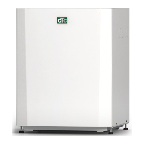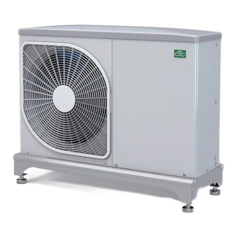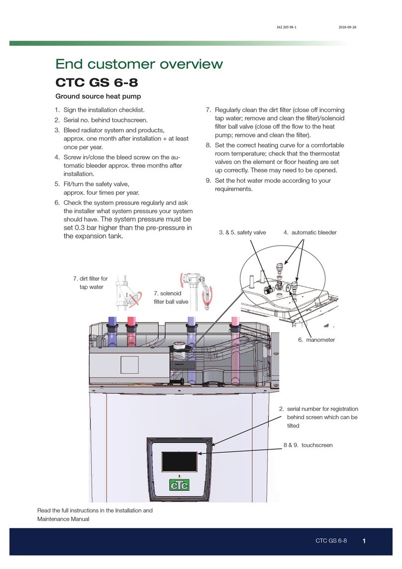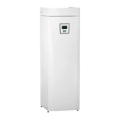
4CTC EcoHeat 400
Table of Contents
Important to remember! ______________________________________________ 6
Safety instructions _______________________________________________________ 7
Checklist _______________________________________________________________________ 8
1. Your home’s heating settings_______________________________ 9
2. Technical data _____________________________________________________ 13
2.1 Table 400V 3N~ ______________________________________________13
Technical data__________________________________________________________14
2.2 Table 230 V 1N~ ______________________________________________15
Technical data__________________________________________________________16
2.3 Table 230 V 3~ ________________________________________________17
Technical data__________________________________________________________18
3. Measurements_____________________________________________________ 19
4. CTC EcoHeat 400 design ___________________________________ 21
5. Parameter list ______________________________________________________ 22
6. Control system ____________________________________________________ 23
6.1 Quick start touchscreen____________________________________24
7. Detailed menu descriptions _______________________________ 26
7.1 Start menu ______________________________________________________26
7.2 Alarm management__________________________________________26
7.3 Heating/Cooling_______________________________________________27
7.4 DHW ______________________________________________________________30
7.5 Ventilation _______________________________________________________30
7.6 Weekly program_______________________________________________31
7.7 Operation data_________________________________________________33
Installer ___________________________________________________________________39
7.8 Display____________________________________________________________39
7.9 Settings __________________________________________________________41
7.10 Define_____________________________________________________________ 53
7.11 Service____________________________________________________________65
8. Operation and Maintenance ______________________________ 69
9. Troubleshooting/Appropriate measures___________ 70
9.1 Information messages ______________________________________ 72
9.2 Alarm messages ______________________________________________73
10. Installation____________________________________________________________ 76
10.1 Transportation__________________________________________________76
10.2 Unpacking_______________________________________________________ 76
10.3 Recycling ________________________________________________________76
11. Pipe installation___________________________________________________ 77
11.1 Filling ______________________________________________________________77
11.2 Schematic diagram __________________________________________78
11.3 Schematic diagram of passive cooling – Combined
cooling/heating ________________________________________________82
11.4 Schematic diagram of passive cooling in separate
heating circuits_________________________________________________83
12. Connecting the brine system_____________________________ 84
12.1 Brine system schematic diagram _______________________86
12.2 Brine pump _____________________________________________________88
13. Electrical installation___________________________________________ 89
13.1 Positioning of electrical components __________________ 91
13.2 Settings to be carried out by the installation electri-
cian ________________________________________________________________93
13.3 Installing a backup power supply _______________________93
13.4 Groundwater heating________________________________________ 94
13.5 Connection of pump (G46) to Differential thermostat
function___________________________________________________________94
13.6 Connection of sensor (B46) to Differential thermo-
stat function ____________________________________________________94
13.7 Resistances for sensors____________________________________95
13.8 Wiring diagram tank 400 V 3N~_________________________ 97
13.9 Wiring diagram tank 400 V 3N~_________________________ 98
13.10 Wiring diagram tank 230 V 1N~_______________________ 100
13.11 Wiring diagram tank 230 V 3~ _________________________ 101
13.12 Wiring diagram tank 230 V 1N~_______________________ 102
13.13 Wiring diagram tank 230 V 3~ _________________________ 104
13.14 Wiring diagram heat pump 400 V 3N~ _____________ 106
13.15 Wiring diagram heat pump 230 V 1N~ _____________ 107
13.16 Component list, wiring diagram _______________________ 108
14. Installation Communication _____________________________ 109
14.1 Installing the network cable _____________________________ 110
14.2 CTC Remote - Screen Mirroring_______________________ 111
14.3 MyUplink - App______________________________________________ 111
15. First start____________________________________________________________ 112
