Energate Foundation User manual

Foundation
Foundation Smart Thermostat & Home Energy
Gateway User Guide for Foundation v1.4
Programmable Communicating Thermostat & In-Home Energy Use Display
www.energateinc.com/foundation
AW000718-H

Legal Declarations
© 2014 Energate Inc. All Rights Reserved.
Foundation Smart Thermostat & Home Energy Gateway User Guide
Information in this document is subject to change without notice.
Energate assumes no responsibility for any errors that may appear in this document.
ENERGATE INC. DISCLAIMS ALL WARRANTIES WITH RESPECT TO THIS DOCUMENT,
EXPRESSED OR IMPLIED, INCLUDING BUT NOT LIMITED TO THOSE OF
MERCHANTABILITY OR FITNESS FOR A PARTICULAR PURPOSE. IN NO EVENT SHALL
ENERGATE DEVICE BE LIABLE, WHETHER IN CONTRACT, TORT, WARRANTY, OR
UNDER ANY STATUTE OR ON ANY OTHER BASIS FOR SPECIAL, INCIDENTAL,
INDIRECT, UNITIVE, MULTIPLE OR CONSEQUENTIAL DAMAGES IN CONNECTION WITH
OR ARISING FROM THIS DOCUMENT, INCLUDING BUT NOT LIMITED TO THE USE
THEREOF.
Notice to Purchaser
Foundation Smart Thermostat is covered by one or more of US Patent Number 7737762, Solid-
State Switch and corresponding claims in their non-US counterparts, owned by Energate Inc.
No right is conveyed expressly, by implication, or by estoppel under any other patent claim.
Trademarks
Energate is a registered trademark. Foundation and Foundation Smart Thermostat & Home
Energy Gateway are trademarks of Energate or its subsidiaries in the U.S. and/or certain other
countries.
All other trademarks are the sole property of their respective owners.
July 2014
1

Warranty
LIMITED WARRANTY OF ENERGATE INC.
Energate Inc. Warrants that this product will be free from defects in material and workmanship
for a period of one (1) year from the date of the original purchase of this product from Energate
Inc. (the “Warranty Period”).
THIS WARRANTY DOES NOT INCLUDE DAMAGE TO THE PRODUCT RESULTING FROM
ACCIDENT OR MISUSE. ENERGATE INC. DISCLAIMS ALL WARRANTIES AND
CONDITIONS. EXPRESS OR IMPLIED, AS TO THIS PRODUCT’S MERCHANTABILITY,
PRODUCTIVENESS OR FITNESS FOR ANY PARTICULAR PURPOSE, INCLUDING ANY
AND ALL WARRANTIES ARISING BY STATUTE OR OTHERWISE IN LAW OR FROM A
COURSE OF DEALING OR USAGE OF TRADE.
If this product becomes defective during the Warranty Period, Energate Inc. shall have the
option, in its sole discretion, to either repair the product or replace the product.
This warranty shall be solely for the benefit of the party that purchases this product directly from
Energate Inc. or one of Energate’s recognized distributors and is not assignable without the
express written consent of Energate Inc.
To obtain warranty service, please contact your electricity provider. A return authorization is
required on all returns relating to a warranty claim. Energate Inc. reserves the right to charge
the purchaser of this product for the costs of shipping replacement products or parts. In the
event that any part of this product is replaced by Energate Inc. during the Warranty Period, any
and every warranty that might be applicable to the replacement part[s) shall expire on the date
of the expiry of the Warranty Period.
ENERGATE INC.’S ENTIRE AGGREGATE LIABILITY FOR LOSSES AND DAMAGES FOR
ANY CAUSE RELATED TO OR ARISING OUT OF THE PURCHASER’S PURCHASE AND/
OR USE OF THE PRODUCT WILL IN NO EVENT EXCEED THE PURCHASE PRICE PAID
FOR THE PRODUCT. IN NO EVENT WILL ENERGATE INC. BE LIABLE FOR: (A) ANY
INDIRECT, SPECIAL, INCIDENTAL, CONSEQUENTIAL OR PUNITIVE LOSS OR DAMAGE,
OR OTHER ECONOMIC LOSS OF ANY KIND, IN ANY CASE, EVEN IF ADVISED OF, OR IF
ENERGATE INC. COULD REASONABLY FORESEE, THE POSSIBILITY THEREOF. THE
LIMITATIONS, EXCLUSIONS AND DISCLAIMERS IN THIS AGREEMENT SHALL APPLY
IRRESPECTIVE OF THE NATURE OF THE CAUSE OF ACTION, DEMAND, OR
PROCEEDING INCLUDING BUT NOT LIMITED TO, BREACH OF CONTRACT,
NEGLIGENCE, TORT, STRICT LIABILITY OR ANY OTHER LEGAL OR EQUITABLE
THEORY.
2

Contents
Legal Declarations..................................................................................................................... 1
Warranty.................................................................................................................................... 2
1 How to use this Guide......................................................................................................... 6
1.1 Purpose....................................................................................................................... 6
1.2 Intended Audience....................................................................................................... 6
1.3 Foundation Models ...................................................................................................... 6
1.4 Text Conventions......................................................................................................... 7
2 About Foundation................................................................................................................ 7
2.1 Operating Foundation.................................................................................................. 8
2.2 LED Indicators............................................................................................................. 9
2.3 Thermostat Display...................................................................................................... 9
2.3.1 Information below the Temperature .....................................................................10
2.3.2 Thermostat Mode Display Symbols......................................................................11
2.3.3 Thermostat Fan Display Symbols ........................................................................12
2.3.4 Scrolling Messages..............................................................................................13
2.4 Energy Display............................................................................................................14
2.5 Standby Display..........................................................................................................16
2.5.1 Switch between Thermostat and Energy Displays ...............................................16
2.5.2 Standby Display...................................................................................................16
3 Main Menu.........................................................................................................................18
3.1 Consumption Information............................................................................................18
3.1.1 Consumption and Cost Data................................................................................18
3.1.2 Track Savings......................................................................................................20
3.2 Mode and Fan Settings...............................................................................................21
3.2.1 Thermostat Mode Settings...................................................................................21
3.2.2 Thermostat Fan Settings......................................................................................22
3.2.3 Change the Thermostat Mode and Fan Settings..................................................22
3.3 Schedule Settings and Temperature Hold...................................................................23
3.3.1 Using a Schedule.................................................................................................23
3.3.2 Temporarily Change the Temperature from the Home Screen.............................24
3.3.3 Display the Schedule Settings Menu....................................................................24
3.3.4 Default Schedule.....................................................................................................25
3.3.5 View the Schedule ..................................................................................................25
3.3.6 Change the Current Schedule..............................................................................26
3.3.7 Create or Reset the Schedule..............................................................................27

3.3.8 Switch to Using a Fixed Temperature..................................................................28
3.3.9 Create a Schedule for the Thermostat.......................................................................30
3.4 Changing the Temperature Using Holds.....................................................................31
3.4.1 Temperature Hold Menu......................................................................................32
3.4.2 Temporary Hold...................................................................................................33
3.4.3 Timed Hold ..........................................................................................................33
3.4.4 Permanent Hold...................................................................................................34
3.4.5 Vacation Hold ......................................................................................................35
3.4.5 Cancel a Hold......................................................................................................36
3.4.7 View a Hold...............................................................................................................37
3.4.8 Edit a Hold...........................................................................................................37
3.4.9 Changing the Temperature Using Holds..............................................................38
3.5 Event Response Settings............................................................................................39
3.5.1 Conservation Settings..........................................................................................39
3.5.2 Event Participation...............................................................................................42
3.5.3 Price Response ...................................................................................................43
3.5.4 Utility Messages...................................................................................................45
3.6 Settings.......................................................................................................................46
3.6.1 Display Options....................................................................................................46
3.6.2 User Options........................................................................................................48
3.6.3 Device Settings....................................................................................................50
3.6.4 Energy & Rate Settings........................................................................................53
4 Utility Events......................................................................................................................55
4.1 Energy Events ............................................................................................................55
4.1.1 Voluntary Energy Events .....................................................................................55
4.1.2 Mandatory Energy Events....................................................................................56
4.2 Price Conservation Events..........................................................................................56
4.3 Blue Utility Event LED.................................................................................................57
4.4 LED Pricing Indicators ................................................................................................58
5 Error Messages..................................................................................................................59
5.1 Low Battery Message .................................................................................................59
5.2 Brown Out Fault Message...........................................................................................60
5.2 Air Filter Message.......................................................................................................60
5.4 Filter Fault Message ...................................................................................................61
5.5 Heat Pump Fault Message..........................................................................................61
5.6 Short Circuit Message.................................................................................................62
4

5.7 Configuration Error Message......................................................................................62
5.8 Low MDC Battery Message ........................................................................................62
6 Installation..........................................................................................................................63
6.1 Installer Setup Menu...................................................................................................63
6.2 Equipment Settings.....................................................................................................63
6.3 Setpoint Range...........................................................................................................66
6.4 Meter Data Collector (FZ100C Model only).................................................................67
6.5 Pager..........................................................................................................................67
6.6 Wi-Fi...........................................................................................................................68
6.7 ZigBee........................................................................................................................68
6.8 Reset..........................................................................................................................69
6.9 Foundation Thermostat Wiring....................................................................................72
6.9.1 Conventional System Wiring................................................................................72
6.9.2 Heat Pump Wiring................................................................................................73
7 Optional Accessories .........................................................................................................73
8 Taking Care of Your Foundation........................................................................................74
8.1 Removing Foundation from the Mounting Bracket.......................................................74
8.2 Replacing the Battery..................................................................................................75
8.3 Re-attaching Foundation to the Mounting Bracket ......................................................76
8.4 Cleaning .....................................................................................................................76
9 Impact of Power Outages...................................................................................................76
10 End-of-Life & Safe Disposal............................................................................................76
11 Technical Specifications.................................................................................................77
11.1 Intended Use ..............................................................................................................77
11.2 Product Conformity.....................................................................................................78
5

1 How to use this Guide
1.1 Purpose
This user guide describes the basic operation of Foundation and how to use Foundation to
maximize your comfort and manage your electricity consumption.
1.2 Intended Audience
This user guide is intended for residential customers enrolled in an energy saving program
offered by their electricity provider.
1.3 Foundation Models
Some Foundation models offer additional features, such as the ability to collect consumption
information from an optional sensor attached to your electricity meter. Whenever it discusses
these features, this guide specifies the Foundation models that support the feature.
FZ100 - Communicates with ZigBee meters to allow you to manage your home energy usage
while providing you with conservation, comfort and convenience.
FZ100C - Incorporates all of the features of FZ100 and provides the optional capability to
receive consumption information directly from your electricity meter using the optional Meter
Data Collector to communicate with non-ZigBee meters.
Contact your service provider for more information about Foundation models.
6

1.4 Text Conventions
Bold text indicates important concepts, and menu options or button names in procedures. For
example: Press the Home button to switch between the Energy display and Thermostat
display on the home screen.
Text with initial capital letters indicates terminology that appears on Foundation screens, such
as menu options or screen titles. For example, User Options Wizard or Set Temporary Hold.
1. Numbers identify multi-step procedures.
This symbol identifies a single-step procedure.
This symbol identifies energy- and money-saving tips.
This symbol identifies warnings.
2 About Foundation
Foundation is a home energy control device that combines fundamental home climate control
and energy consumption management. It allows you to control your home’s temperature, and to
manage your energy consumption and costs:
•Program the temperatures settings according to your schedule.
•Manage your home’s energy consumption and your energy costs based on the price of
electricity. You can prioritize either cost savings or home comfort, or create a
comfortable balance between the two.
7

2.1 Operating Foundation
Foundation uses advanced climate control algorithms to control your central heating and cooling
systems. It also determines and displays how much electricity you are using and how much it
costs.
Button Button Name Functions
Home
•Switches between the Thermostat and the Energy displays.
•Exits and cancels any changes within a menu. Pressing the
Home Button repeatedly will return you to the home screen.
•Wakes up the device.
Menu/Select
•Displays a menu.
•Selects the highlighted item.
•Navigates to the next step in a wizard.
•Confirms messages
•Wakes up the device
Up
and
Down
•Moves the highlighted selection in a menu.
•Wakes up the device
•Adjusts the target temperature from the home screen
•Adjusts the value within a menu
8

2.2 LED Indicators
Foundation has four light-emitting diodes (LED) that signal events from your electricity provider.
Each LED illuminates for the duration of the corresponding event.
The Blue LED indicates that an energy or price conservation event is in effect and has triggered
the thermostat to adjust the temperature.
As the price of electricity rises, the yellow, orange, and red lights illuminate in that order, to
indicate increasing prices.
For more information about utility events and the LED Indicators, see 4Utility Events
2.3 Thermostat Display
The Thermostat display provides direct access to the household climate control features.
•The outdoor temperature is not displayed if an outdoor temperature sensor is not
installed. For more information, see 7 Optional Accessories
•If the time is not displayed, set it using user options. For information, see 3.6.2 User
Options.
•Link status:
oIndicates that the communications link to the electricity provider's
server is connected. The signal quality ranges from the lowest signal quality (1
bar) to the highest signal quality (5 bars).
oFoundation is configured to receive utility events and other information
via a ZigBee network.
oFoundation is configured to receive information via the optional FlexNet
pager module.
9

oFoundation is configured to receive utility events and other information
via a Wi-Fi network.
oFoundation is configured to receive information via both ZigBee and
the Wi-Fi or pager module (for Dual).
oIndicates that the link is not connected.
•The scrolling message indicates what the thermostat is doing. For more information
about the scrolling messages, see 2.3.4 Scrolling Messages.
2.3.1 Information below the Temperature
The following types of information can appear below the temperature:
•TARGET – ”Temperature”°: The thermostat is controlling the HVAC equipment as
needed to reach the target temperature. When the thermostat mode is OFF, this line is
blank.
•ENERGY EVENT UNTIL ”Time”: The electricity provider has sent an energy event to
adjust your thermostat target temperature or thermostat duty cycle.
•CONSERVATION UNTIL ”Time”: The thermostat has adjusted the temperature in
response to an electricity price increase.
•TEMPORARY UNTIL ”Time”: The temperature has been adjusted temporarily until the
next schedule change.
•PERMANENT HOLD IN EFFECT: A permanent hold has been set.
•TIMED UNTIL ”Date”: A timed or vacation hold has been set.
10
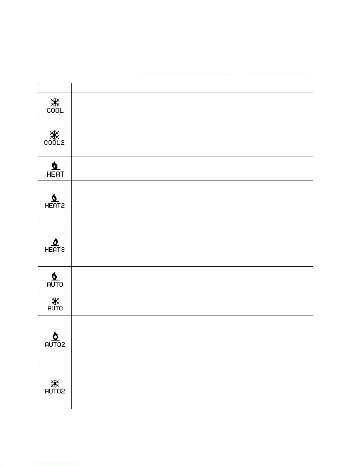
2.3.2 Thermostat Mode Display Symbols
The following table describes the thermostat display symbols that appear on the Thermostat
display. For more information see 3.2.1 Thermostat Mode Settings and 6.2 Equipment Settings.
Symbol
Description
COOL: The Thermostat Mode is set to Cool. The symbol displays regardless of
whether the cooling equipment is running. This setting is available only when one
or more cooling stages are enabled in the Equipment Settings.
COOL2: The Thermostat Mode is set to Cool. The cooling equipment is running,
and the second cooling stage is enabled, either when the cooling equipment has
run longer than the Recovery Time, or when you change the target cooling
temperature while the cooling equipment is running. This setting is available only
when there are two cool stages enabled in the Equipment Settings.
HEAT: The Thermostat Mode is set to Heat. The symbol displays regardless of
whether the heating equipment is running. This setting is available only when one
or more heating stages are enabled in the Equipment Settings.
HEAT2: The Thermostat Mode is set to Heat. The heating equipment is running,
and the second heating stage is enabled, either when the furnace has run longer
than the Recovery Time, or when you change the target heat temperature while
the heating equipment is running. This setting is available only when two or more
heating stages are enabled in the Equipment Settings.
HEAT3: The Thermostat Mode is set to Heat. The heating equipment is running.
The symbol displays when the third heating stage is enabled, either when the
heating equipment has run longer than the Recovery Time, or when you change
the target heating temperature while the HEAT2 equipment is running. This
setting is available only when three heating stages are enabled in the Equipment
Settings.
AUTO (heat): The Thermostat Mode is set to Auto. The heating equipment is
either running, or was the last equipment to run. This setting is available only
when heating and cooling stages are enabled in the Equipment Settings.
AUTO (cool): The Thermostat Mode is set to Auto. The cooling equipment is
either running, or was the last equipment to run. This setting is available only
when heating and cooling stages are enabled in the Equipment Settings.
AUTO2 (heat): The Thermostat Mode is set to Auto. The heating equipment is
running, and the second heating stage is enabled, either when the furnace has
run longer than the Recovery Time, or when you change the target heating
temperature while the heating equipment is running. This setting is available only
when heating and cooling stages are enabled in the Equipment Settings, and
when more than one heating stage is enabled.
AUTO2 (cool): The Thermostat Mode is set to Auto. The cooling equipment is
running and the second cooling stage is enabled, either when the cooling
equipment has run longer than the Recovery Time, or when you change the target
cool temperature while the cooling equipment is running. This setting is available
only when heating and cooling stages are enabled in the Equipment Settings, and
when more than one cooling stage is enabled.
11

AUTO3 (heat): The Thermostat Mode is set to Auto. The heating equipment is
running, and the third heating stage is enabled, either when the furnace has run
longer than the Recovery Time, or when you change the target heating
temperature while the HEAT2 equipment is running. This setting is available only
when heating and cooling stages are enabled in the Equipment Settings, and
when three heating stages are enabled.
OFF: The Fan Setting is set to Off. Use this setting to ensure that no equipment
runs. This setting is available with any equipment setup.
EMERG: The Fan Setting is set to Emergency Heating. The emergency heating
equipment is running. This symbol displays only when you select emergency
heating. This setting is available only when the Equipment Type is Heat Pump,
and there are more heating stages than cooling stages.
2.3.3 Thermostat Fan Display Symbols
The following table describes the fan symbols that appear on the Thermostat display.
Symbol Description
ON: The Fan Setting is set to On. The fan runs continuously.
AUTO: The fan runs only when the heating or cooling systems are on.
For more information, see 3.2.2 Thermostat Fan Settings.
12
2.3.4 Scrolling Messages
The following tables provide information about the scrolling messages that appear at the bottom
of the display.
Information Messages
Message
Description
Following Schedule Displayed when the scheduled target temperature is the active
target temperature.
[Heating/Cooling] to [target
temperature] Displayed when there is a vacation hold is set but not yet in
progress.
Hold [Heat/Cool] at [active
target temperature] Displayed when there is a hold in progress.
No Hold active Displayed when the system is running the equipment.
Anticipating for [next target
temperature] ° Displayed when the thermostat is anticipating a scheduled target
temperature change (for example, the HVAC equipment is
heating or cooling to reach the target temperature at the
scheduled time).
[Second / Third] stage on Displayed when more than one stage is on.
Aux. Heat On Displayed when the emergency heat stage is engaged.
Rate: [current price][*] Displayed when electricity pricing information is available. The
current price is displayed in either cents or dollars, depending on
the current price. A star indicates that you manually entered the
price and rate information in Foundation, and that it does not
come from the meter.
Limiting [heat/cool] To
[active target temperature] Displayed when an energy event or price conservation event is
in progress.
Limiting Usage To [event
duty cycle]% Displayed when a utility event is in progress, and the duty cycle
is the limiting factor or is the only field that is specified in the
event (no temperatures are specified).
Please Change Filter Displayed on the scheduled Filter Reminder date. For
information about setting the Filter Reminder, see 3.6.2 User
Options.
Pre-Heating/Cooling Displayed when the thermostat is anticipating a price
conservation event, and is using an off-peak opportunity to heat
or cool the home before the scheduled price increase.
13

Error Messages
Message
Description
Configuration Error Displayed when there is a problem with the thermostat.
Short Circuit Detected Displayed when a short circuit is detected in the wiring between
the thermostat and the HVAC equipment.
Low Battery Displayed when the battery level is low.
Filter Fault Detected Displayed when a filter hardware fault is detected.
Heat Pump Fault Displayed when a heat pump hardware fault is detected.
Brown Out Fault Displayed when there is a brown out.
Low MDC Battery Displayed when the optional Meter Data Collector battery is low.
For information on responding to error messages, see 5 Error Messages.
2.4 Energy Display
The Energy display provides at-a-glance consumption data and access to historic data and
energy consumption information to help you make informed decisions about your home comfort
and energy consumption.
•The outdoor temperature is not displayed if an outdoor temperature sensor is not
installed. For more information, see 7 Optional Accessories.
•A star next to the price indicates that you are not receiving price information from your
electricity provider. The price is based on the load information settings entered in the
Energy Settings menu, see Price and Rate Information. When the price comes from the
electricity provider, there is no star next to the price.
14

•Link status:
oIndicates that the communications link to the electricity provider's
server is connected. The signal quality ranges from the lowest signal quality (1
bar) to the highest signal quality (5 bars).
oFoundation is configured to receive utility events and other information
via a ZigBee network.
oFoundation is configured to receive information via the optional FlexNet
pager module.
oFoundation is configured to receive utility events and other information
via a Wi-Fi network.
oFoundation is configured to receive information via both ZigBee and
the Wi-Fi or pager module (for Dual).
oIndicates that the link is not connected.
•The source for the energy consumption data is either HOME or HVAC:
oHOME: The consumption data comes from the meter through either ZigBee or
the optional Meter Data Collector. Foundation displays the electricity
consumption for the whole home.
oHVAC: The consumption data comes from the thermostat. Foundation displays
the electricity consumption for only the heating and cooling system. The data is
based on the load information that is entered in the Energy Settings menu. For
more information about the load information, see Load Information for your
HVAC Equipment.
•The current electricity use reflects the amount of electricity that is being used in the
home in kilowatts (kW).
To see how low your current electricity use can go when in HOME
consumption data mode, turn off the lights and unplug your electronic devices
when everyone is away or asleep. The lower this value is, the more you can
save.
•The cost per hour is how much it costs you to consume that amount of energy for one
hour.
•The scrolling message indicates what Foundation is doing. For more information about
the scrolling messages, see 2.3.4 Scrolling Messages. For more information about error
messages, see 2.3.4.2 Error messages.
15

2.5 Standby Display
After a period of inactivity, the thermostat switches to Standby display.
2.5.1 Switch between Thermostat and Energy Displays
You can switch between the Thermostat display and the Energy display when either display is
active.
From a display, press the Home button to switch between the Thermostat display and the
Energy display.
2.5.2 Standby Display
By default, the display automatically dims after a period of inactivity.
To wake up the system, press any button. The screen lights up and displays the last
display screen visited.
You also can configure Foundation to display a different screen when it is in standby mode.
All standby screens display the current indoor temperature or target temperature (for example,
the scheduled temperature) at the bottom left. Current indoor temperatures are accompanied by
a symbol that indicates the current thermostat mode (see 3.2.1 Thermostat Mode Settings).
The cost of electricity per hour, based on current usage, is displayed at the bottom right.
Standby Screens
Time & Date: Displays the current time and date.
Temperature: Displays the current indoor temperature, the
thermostat mode and fan setting.
16

Energy Consumption: Displays the cost of electricity used
in the previous 24 hours and the average daily cost for the
past 7 days.
The bar graph on the left compares the 24-hour cost to
average daily cost for the past 7 days. For example, if the
bar is completely solid, the 24-hour cost is the same or
higher than the highest daily cost in the past week.
The bar graph on the right compares the average cost of
the past 7 days to daily costs for the past 7 days. For
example, if the bar is half-filled, the average 7-day cost is
halfway between the lowest and highest daily cost in the
past 7 days.
A smiling face is displayed between the bar graphs if the
cost of the last 24 hours is less than or equal to the current
7-day average.
A neutral face (straight mouth) is displayed if the 24-hour
cost is above the 7-day average.
You can also configure the brightness of the display in standby display. For information on
configuring the standby screen, see 3.6.1 Display Options.
17

3 Main Menu
The main menu lists the settings that you can configure.
1. From the home screen, press the Menu/Select
button to display the main menu.
2. Press the Up
and Down
buttons to navigate through the menu options.
3.1 Consumption Information
3.1.1 Consumption and Cost Data
Foundation displays the Consumption Information on a series of screens.
1. From the home screen, press the Menu/Select
button to display the main menu.
2. Press the Up
or Down
button to highlight Consumption Information, and then
press the Menu/Select
button.
3. Read the information, and then press the Menu/Select
button to navigate to the next
screen.
Current Energy Cost: Shows the current cost of the
electricity you are using and the minimum, maximum, and
average cost for the previous day.
The current value displays the cost for the next hour if you
maintain the current level of usage.
Current Energy Use: Shows the current amount of
electricity you are using and the minimum, maximum, and
average usage for the previous day.
The current value estimates electricity consumption for the
next hour if you maintain the current level of usage.
18

Daily Energy Cost: Shows the electricity cost for the
previous 24 hours and the minimum, average and maximum
daily cost for the last seven days.
Daily Energy Use: Shows the electricity usage for the
previous 24 hours and the minimum, average and maximum
daily usage for the last seven days.
Monthly Energy Cost: Shows the electricity cost for the
month to date, the estimated cost for the entire month, the
cost for the previous month, and the cost for the same month
in the previous year.
Monthly Energy Use: Shows the total electricity
consumption in kWh. Shows usage for the month to date, the
estimated usage for the entire month, and the usage for the
previous month and the same month in the previous year.
Note: If Foundation does not have enough consumption history data, it displays N/A.
19
Other manuals for Foundation
4
Table of contents
Other Energate Gateway manuals


Popular Gateway manuals by other brands


ZKTeco
ZKTeco C3-100 user manual

Endress+Hauser
Endress+Hauser Fieldgate FXA320 operating instructions

ZyXEL Communications
ZyXEL Communications ZyWALL 70 quick start guide

molex
molex CoreSync MechoShades installation instructions

HMS
HMS Anybus Modbus-TCP/RTU Gateway user manual

RTA
RTA 460ETCBM-NNA4 Product user guide


