Energenics FRP-4 User manual

1
www.energenics.com
1470 Don Street Naples, Florida 34104 Telephone: (239) 643-1711
Fax: (239) 643-6081
Customer Service: (800) 944-1711
Installation & Operation Manual
For ENERGENICS
In-Line Space Saver Lint Filters
Descriptions Page
Table of Contents 1
Description of Lint Filter Operation 2
Lint Filter Control Sequence of Operation 3
Receiving and Installation 4
Important Installation Considerations 5
Warnings/Cautions 6
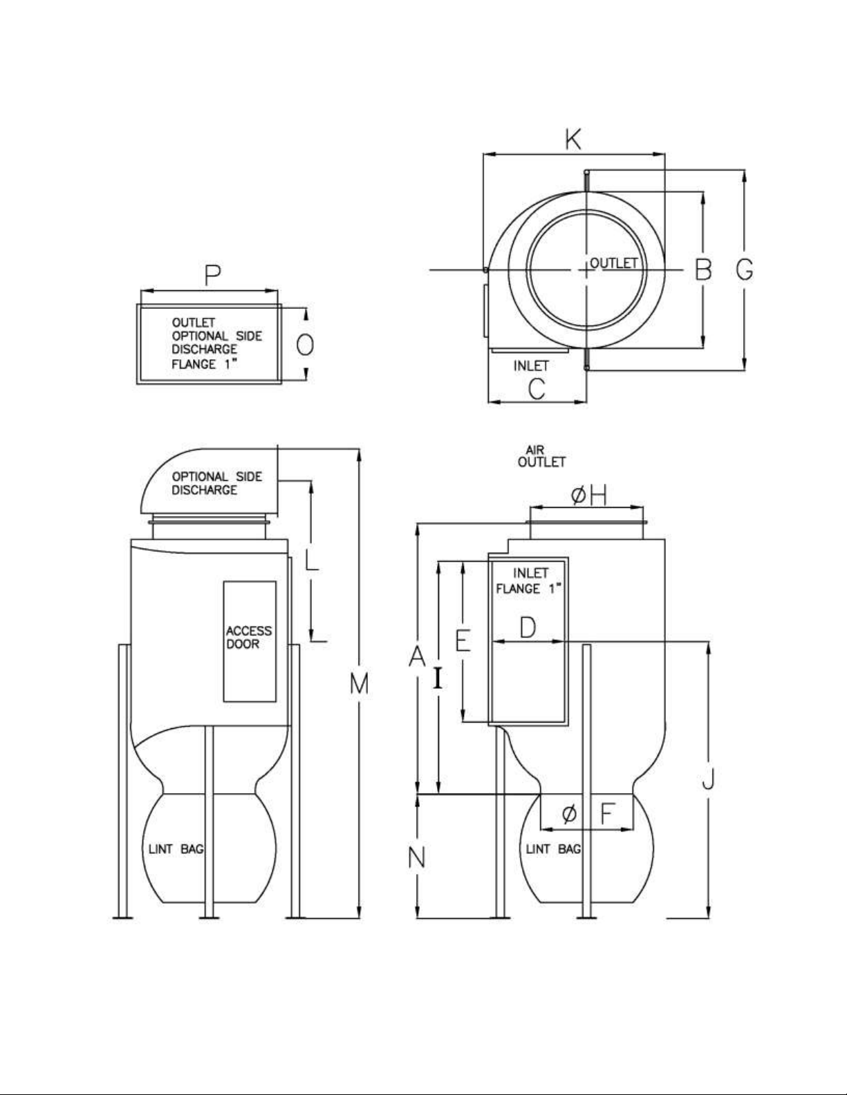
Dimensional Drawing 7
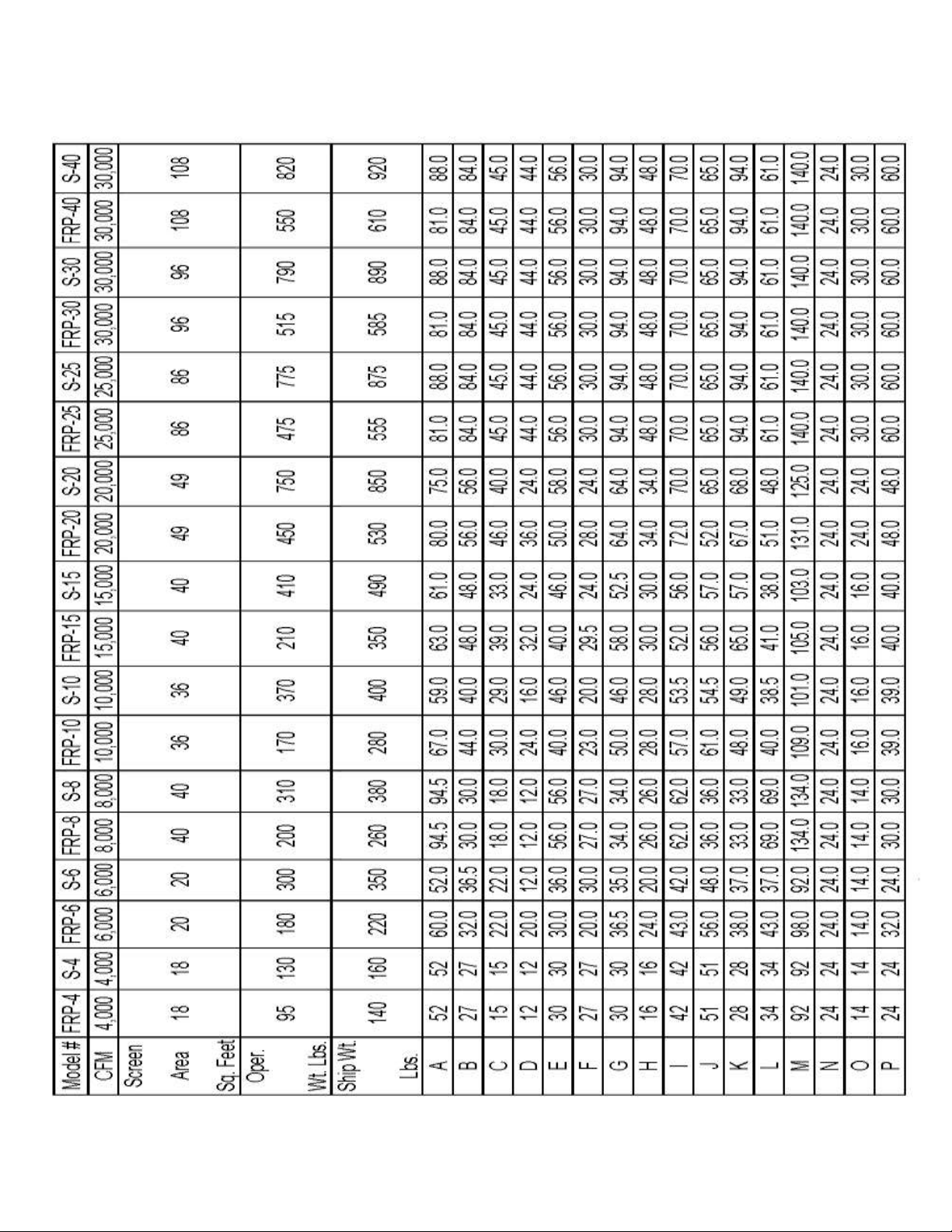
Dimensional Table 8
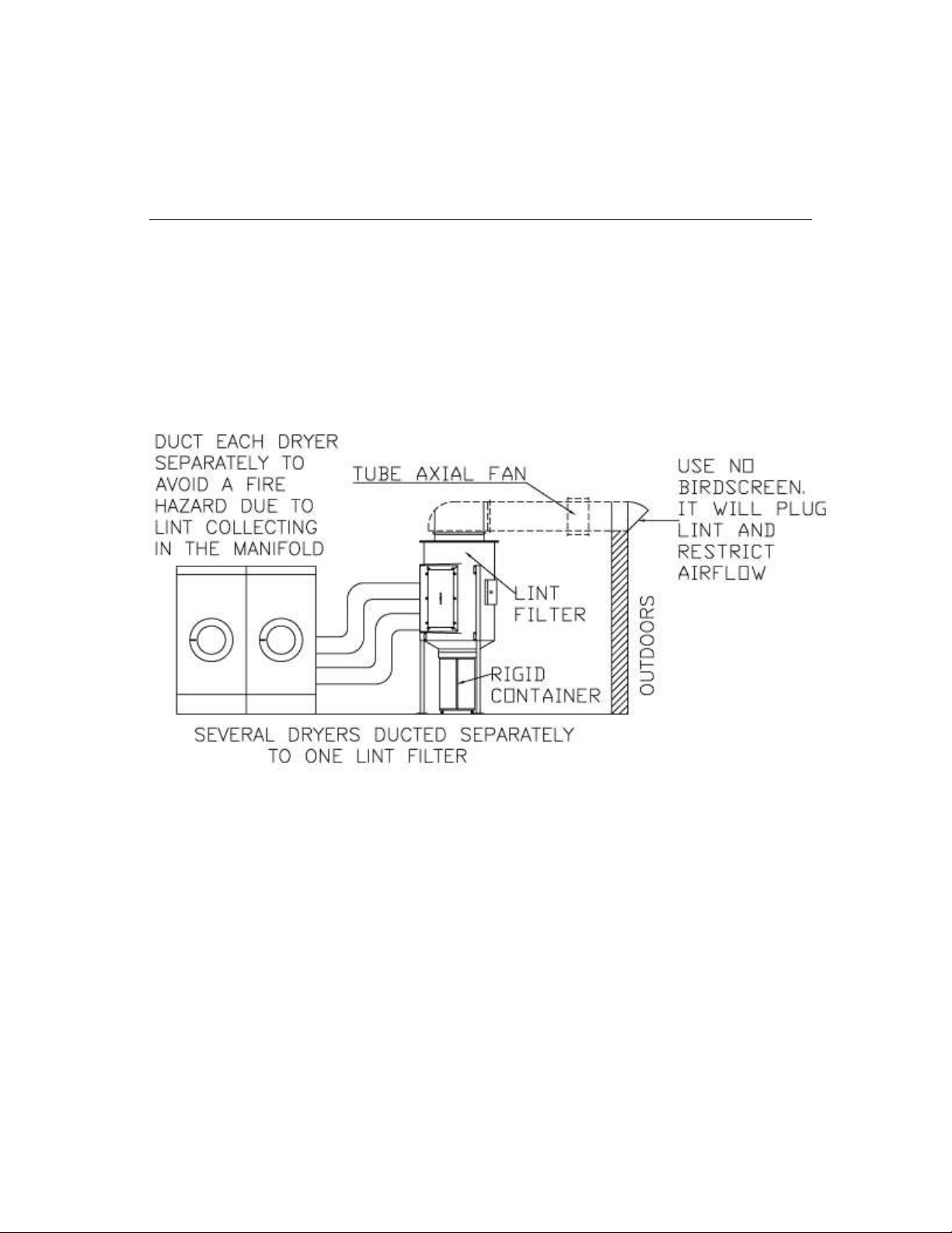
Typical Installation – Without Optional AFO (Booster Fan) 9
Typical Installation – With Optional AFO (Booster Fan) 10
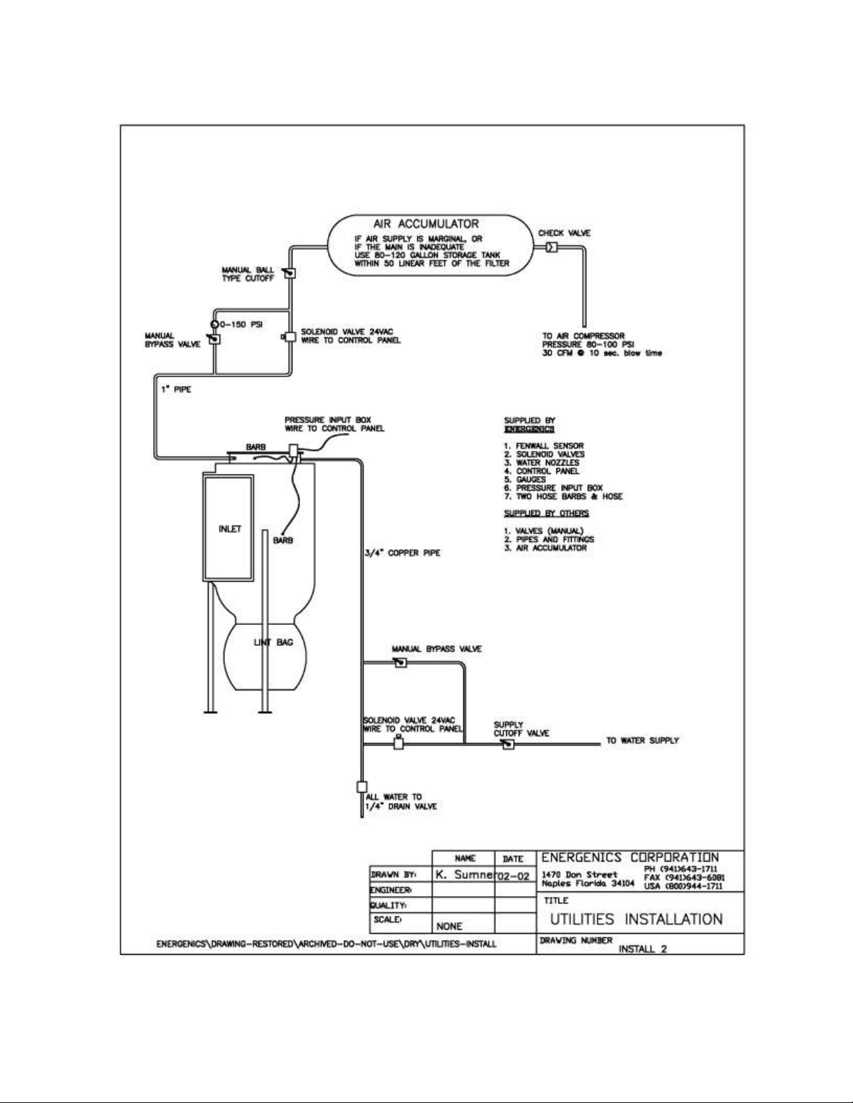
Utilities Installation 11
Sheet Metal Installation 12
Compressed Air Requirements 13
Fire Suppression Water System (optional) 14
Proper Application with Booster Fans & Variable Frequency Drives 15
007 Control Installation Instructions:
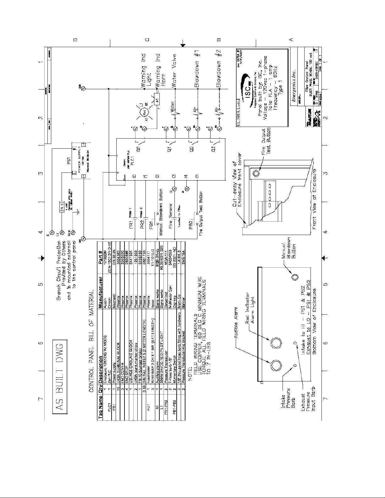
Omron Obsolete UL® Control Schematic & Wiring Diagram 16
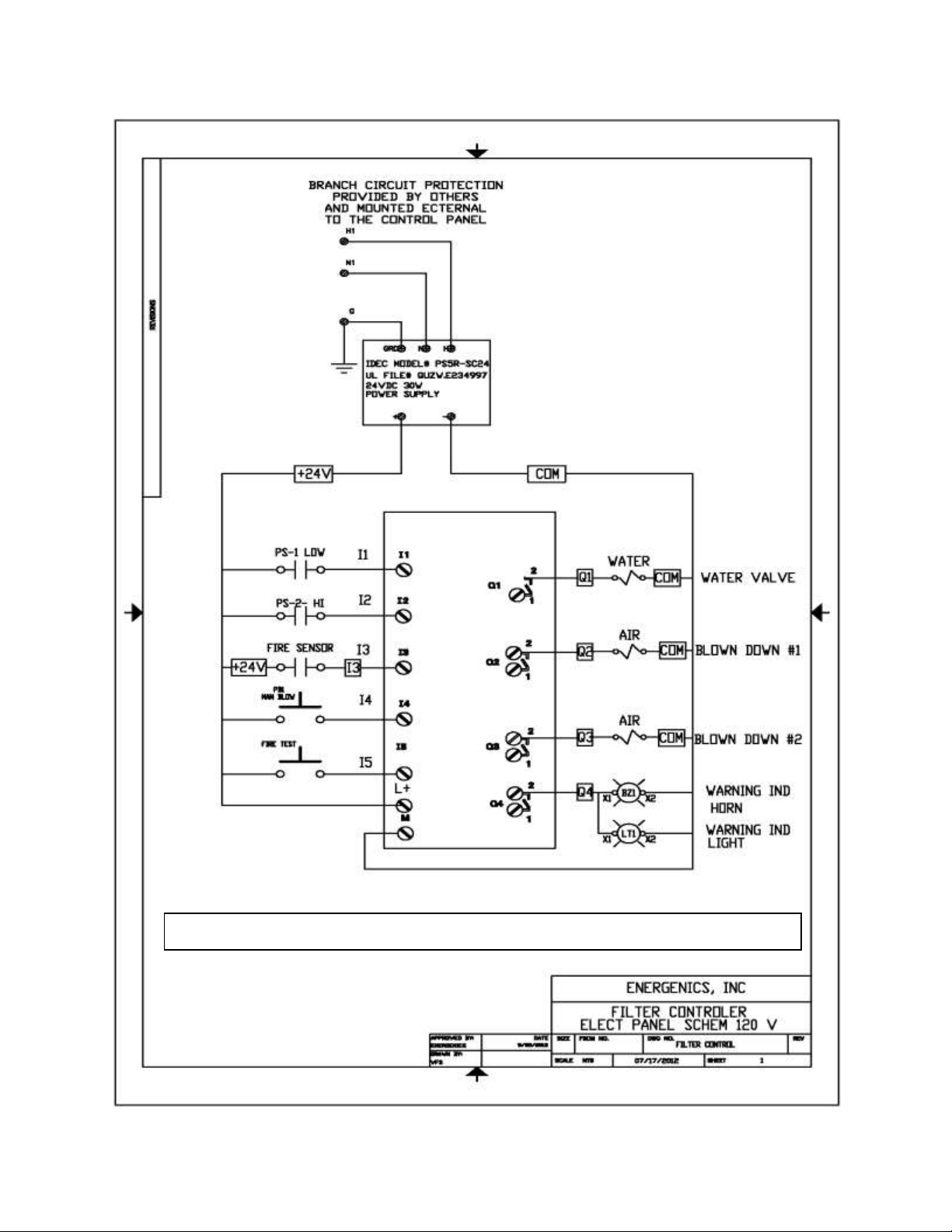
IDEC Obsolete UL® Control Schematic & Wiring Diagram 17
IDEC UL®PLC CONTROL
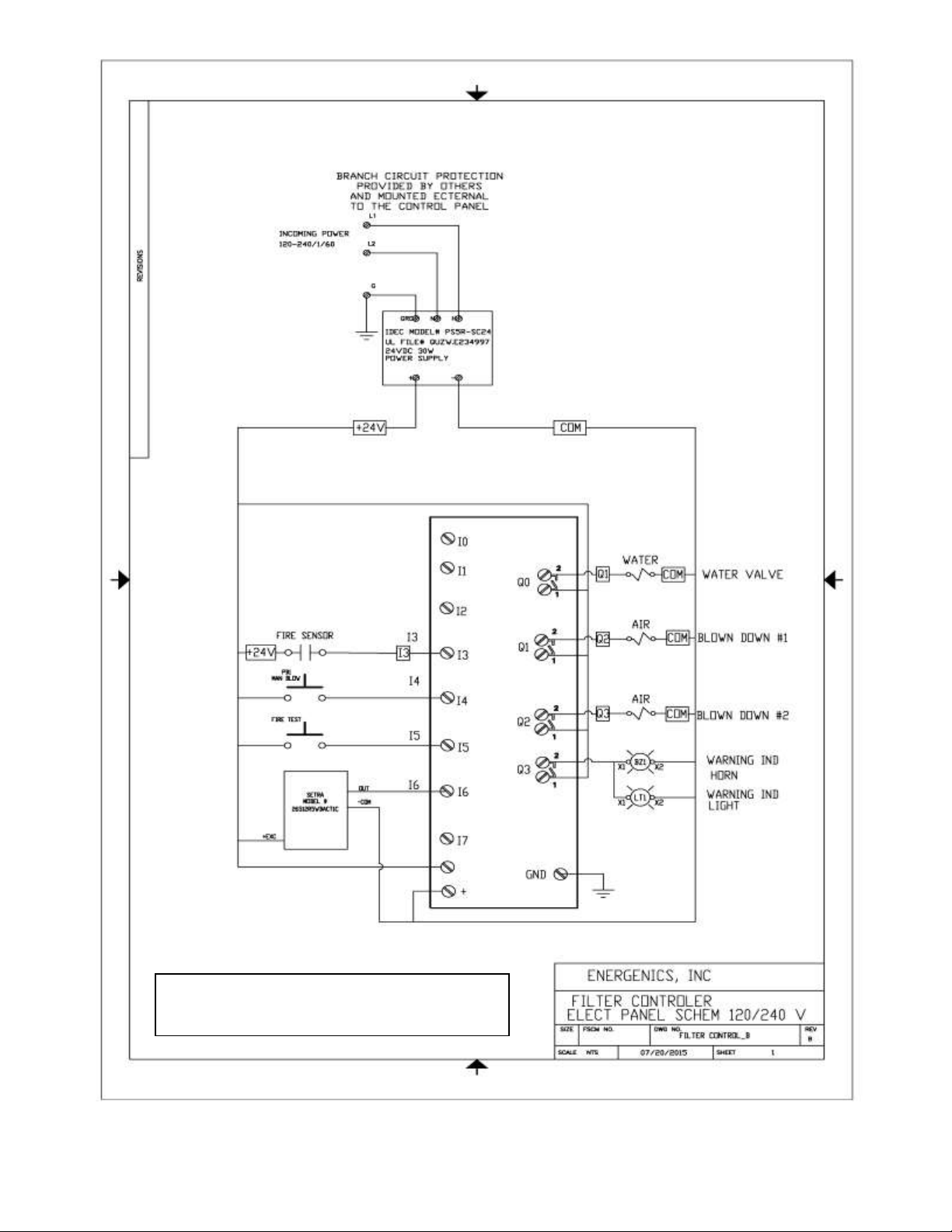
IDEC UL® PLC Control Schematic & Wiring Diagram 18
Change Blowdown & Excess Pressure Set-Point 19
Change Timed Blowdown Intervals 20
Disable Blowdown when all Dryers turn off 21
Tubing Connections (Shown with Optional Airflow Optimizer if Ordered) 22
Connection Requirement 9002.5 23
Connection Requirement (Side View) 9002.6 24
Maintenance Requirements 25

2
DESCRIPTION OF LINT FILTER OPERATION
Your new Energenics Lint Filter operated with a UL approved control represents
the most advanced features available in the laundry industry to date. The
following list the functions and mode of operation:
Blowdown (cleaning) – The Lint Filter will monitor the system backpressure and
automatically initiate the blowdown cycle. As the screen loads with lint, the back
pressure will increase and will result in an automatic blowdown (cleaning) when
the backpressure reaches a set reference (default is .5” w.c.). The lint filter will
also blowdown at the end of every dryer cycle to insure complete screen cleaning
when dryers are turned off. 70% of the lint will be removed from the screen even
though the dryer(s) may be operating. During the blowdown with dryers off,
100% of the lint will be removed from the screen. A manual blowdown can also
be done by depressing the button on the bottom of the Lint Filter control. Note
that automatic blowdown cannot occur within 20 seconds of a prior
blowdown. This is done to allow the compressed air supply to partially recover.
Optional Excess Pressure Alarm – If for any reason the Lint Filter has not blown
down properly (i.e.: compressor turned off) the system will sense a higher
backpressure than normal. In this event the siren and the strobe light both
activate. The Filter control will attempt to blowdown every 20 seconds until the
excess backpressure condition has terminated. If this condition persists, a
manual inspection of the lint screen and observation of proper blowdown must be
done.
Optional Fire Control System – A normally open sensor located inside of the filter
at the top of the inlet will close at 275 degrees F. The control will open the water
solenoid, illuminate the strobe as well as energize the siren. The alarm will be
active until 30 seconds after the temperature has dropped below 275 degrees F.
After 30 seconds the alarm will automatically reset. Inside the control box is a
Fire Control test button. Depress the button and the Fire Control will be activated
for the duration the button is pressed. The function of the test button is to check
the circuit. It does not test the sensor itself. Using a propane torch to the sensor
will test the complete system.

3
LINT FILTER CONTROL SEQUENCE OF OPERATION
1. Dryers Operating When backpressure reaches the field adjustable setpoint
(default .7” W.C.) the air blowdown solenoid is activated for 10 seconds. There is
a field adjustable delay (default 10 seconds) before the blowdown will occur. The
air solenoid will continue to activate for 10 seconds at 3 minute intervals until
backpressure is below the field adjustable setpoint. The 3 minute interval will
allow the compressor to refill.
2. Dryers Excess Pressure Alarm When Operating When backpressure reaches
the field adjustable setpoint (default 1.5” W.C.) the warning indicator horn and
light will be activated continuously until the backpressure drops below the field
adjustable setpoint.
3. After Dryers Turn Off When backpressure drops to 0” W.C. the air blowdown
solenoid is activated for 10 seconds. There is a field adjustable delay (default 10
seconds) before the blowdown will occur This should occur only 1 time when all
the dryers are off. This should reset only when 1 or more dryers turn on and not
until the backpressure reaches .7” W.C. (Field Adjustable).
4. Manual Blowdown Operation When the button on the bottom of the filter control
is depressed, the air blowdown solenoid is activated for 10 seconds. The control
will require 3 minutes before another manual blowdown can be completed.
5. Fire Control If the temperature exceeds 260 degrees Fahrenheit the water
solenoid will open and the warning indicator horn and light will be activated
continuously until the temperature goes below 260 degrees Fahrenheit for 30
seconds. At which point the fire control will completely reset.
6. Manual Fire Control Test Inside the filter control is a black button. When the
button is depressed the water solenoid will open and the warning indicator horn
and light will be activated as long as the button is pressed.
7. Timed Interval Blowdown At a timed interval (default 2 hours) the air blowdown
solenoid is activated for 10 seconds.
8. Optional Vacuum Output When the Air Solenoid is activated a 24 VDC output
on Blowdown 2 activates. If the lint filter is equipped with the Energenics lint
evacuation vacuum system this operates the vacuum system and opens the gate
valve on the filter for 20 seconds. The timer starts at the same time the air
solenoid is activated.
OUTPUTS FROM FILTER CONTROL
Q1-Water Solenoid Valve
Q2-Air Solenoid Valve
Q3-Optional Vacuum Output

4
RECEIVING AND INSTALLATION
Before you sign the Bill of Lading:
1. Receiving- Inspect units inside and out for signs of damage
Verify all components are delivered per the Bill of Materials.
Report damage to the carrier IMMEDIATELY.
Note ALL damage on the Bill of Lading.
This is your responsibility and you must file all claims.
The filter is fully assembled and ready for installation. The
control, valves, and lint bag are in the cardboard box.
2. Installation- Follow instructions herein:
Determine the location with reference to minimum duct work from the dryer
and ease of access for inspection.
If using a lint drop pipe allow enough room for lint to travel down 4’ before the
first bend. Max bend angle is 30 degrees.
If using lint bag or container make sure adequate clearance is allowed.
Conduit or Sealtight between filter junction boxes should be ¾ inch.
Dependant on options ordered, not all outputs will have connected
components.
If the Fire Control Option is NOT ordered the installer must supply a junction
box to connect the wires from the solenoid valve to the Control Box.
When mounting the filter overhead, mount the control below the filter where it
can be easily accessed.
If this Lint Filter has a downstream fan, do not use the supplied lint bag. You
must use a flexible connector and rigid drum (drum sourced locally). If we
supplied the fan then we will have the flexible connector in the box.

5
IMPORTANT INSTALLATION CONSIDERATIONS
All Energenics Lint Collectors can be mounted indoors or outdoors. If it is
mounted outdoors we recommend our Side Discharge or a field installed swept
radius elbow (Gooseneck). Do not use a conical cap on the filter exhaust
discharge. All solenoid valves should be located inside the building. Also, mount
the supplied air pressure gauge at the blowdown pipe on top of the filter.
All solenoids should be mounted as close to the filter as possible, but ALWAYS
inside the building. This will allow most of the air and water (if equipped with
optional Fire Control) piping to remain pressure charged for most efficient
operation.
All wiring should be a minimum of 18 gauge for proper operation.
The Filter Control box should be located in a position to be easily seen and in
close proximity to personnel. In other words if the Filter Control is located
outdoors, 20 feet in the air or in another room away from the laundry personnel,
this would be the wrong location. Lint Filter controls should never be mounted
outdoors.
Since the Filter uses compressed air it is important that the air receiver (if
equipped) be located as close to the filter as possible. The longer the pipe runs
the more restrictive. You will need to increase the pipe diameter if the run is very
long (e.g.: 60 feet).
If the installation is a multi-dryer/multi-duct installation it may be necessary to use
backdraft dampers to prevent lint backflow into the ducts of turned off dryers.
Most dryers have them available as standard equipment or can be ordered to
add on.
After everything is mounted and utilities turned on press the manual blowdown
button located on the bottom of the Filter Control. The rotor on the inside the lint
filter should spin. Make sure that the air pressure at the filter starts out at 100
and ends at about 60 at the end of the blowdown cycle. If it is too low the rotor
won’t turn.
If the Filter is equipped with Fire Suppression, the test button is on the inside of
the Filter Control. It is on the inside to keep people from pushing the button as
they walk by. When the button is pushed the strobe and siren will go on along
with the water solenoid valve. The system operates until the button is no longer
depressed.

6
WARNINGS AND CAUTION
You have purchased the finest lint filter available for your facility. Please follow
these instructions to ensure a safe long life for your filter and facility.
FAILURE TO FOLLOW THESE INSTRUCTIONS CAN RESULT IN AN
UNSAFE OPERATING CONDITION, INCLUDING THE POSSIBILITY OF FIRE.
DO NOT OPERATE ANY DRYER CONNNECTED TO THIS FILTER WITHOUT
BEING CERTAIN THE FILTER STARTUP HAS BEEN COMPLETED AND THE
FILTER IS IN OPERATING CONDITION.
Insure it is installed in compliance with local codes.
Step 1. Install the compressed air (Fire suppression plumbing if ordered), and
piping system(s) including solenoid valves. If the filter is in position,
make all final connections.
Step 2. Mount the 007 control in a visible location on a solid vibration free
surface and connect all components.
Step 3. Provide dedicated 120-240V single phase electrical service to the PLC and
test all systems
Step 4. Install sheet metal and ducting.
START UP AND OPERATION INSTRUCTIONS
Inspect the filter installation. Is it complete? Review the entire installation
requirements prior to startup.
1. Verify the 007 control wiring.
2. Test the blow down cycle (push manual button on control).
Watch the pressure gauge. It should start around 100psi and should not drop
below 60psi during the 10 second cycle.
The rotor should turn 6-12 times during blow down. The rotor propulsion is
adjustable by increasing the number of horizontal holes on the top horizontal
portion of the rotor end.
3. Review maintenance requirements and establish a regular PM schedule.
CAUTION - DO NOT OPERATE FILTER WITH BOOSTER
FAN WITHOUT BAROMETRIC DAMPER OR VARIABLE
SPEED DRIVE!!!!!!!!
(CONSULT PAGE 15)
7
8

9

10
11

12

13

14
15
Service Bulletin #2
August 23, 2016
PROPER APPLICATION OF LINT FILTER ON DRYERS WITH BOOSTER FANS
Introduction: Sets of 35lb. /150lb. Dryers are normally installed with only the lint drawer
underneath the dryer, which does not collect all of the lint. The lint which bypasses the drawer
collects in the ductwork and becomes a fire hazard. This hazard can be eliminated by adding
an Energenics Lint Filter as shown below, with a booster fan equipped with a Variable
Frequency Drive to overcome the resistance of the long ductwork to relieve any vacuum inside
the lint Filter.
Application: Provide a booster fan if the ductwork is excessive. Balance the airflow through
the systems with all dryers running (i.e. slight positive pressure on the outlet of the lint filter).
This will allow the rated airflow through each dryer and each dryer will run well (one can
measure the actual airflow with a pitot tube, if necessary). This will allow the dryers to work
as designed and the lint to fall off the lint screen, as designed.
Energenics supplies the Booster Fan controlled with a Variable Frequency Drive monitoring
back pressure equipped with a pressure transducer to allow the Variable Frequency Drive
to operate in PID mode. The back pressure should be between 0” - .12” W.C. Default
value is .12" W.C. Energenics can supply this package as a system branded “Airflow
Optimizer”.
Locate Lint Filter as near as possible to the dryers to collect all the lint before it
accumulates in the duct system, to keep the duct system free of lint. The
recommended location of the fan is close to the filter on the discharge side.
16
17
OLDER STYLE USING DWYER BLACK PRESSURE SWITCHES
18
NEWER STYLE USING 1 SETRA
ANALOG PRESSURE TRANSDUCER

19
INSTRUCTIONS TO CHANGE BLOWDOWN & EXCESS PRESSURE SET-POINT ON LINT
FILTER CONTROL WITH SETRA PRESSURE TRANSDUCER
1. Start at the “HOME SCREEN”. The Home Screen is indicated with “SYSTEM IS OK” and a display at the
bottom with a bar at the bottom indicating -2.5”-+2.5” W.C.
2. Press the “Down” arrow once to display the “Running Screen”.
3. Press and hold the “ESC” button. While holding down the “ESC” button press the “OK” button, then
release both buttons to display “Device Monitor” (#2 of 4 selections listed).
4. Press “Down” arrow to Device Manager
5. Press “OK” button.
6. To change Blowdown set-point press “Left” Arrow to “D000” (#1 of 4 selections listed).
7. Press and hold the “OK” button until arrow is displayed next to “D000”. Release “OK” button.
8. Press “OK” button to highlight the value field, then release.
9. Pressing the “Left” or “Right” buttons will highlight each digit.
10. When desired digit is “blinking” press the “Up” or “Down” button to increase or decrease the value.
11. When desired value is displayed, press the “OK” button.
12. To change Excess Pressure set-point press “Down Arrow” button until display arrow is adjacent to “D001”
(#2 of 4 selections listed).
13. Press “OK” button to highlight the value field, then release.
14. Pressing the “Left” or “Right” buttons will highlight each digit.
15. When desired digit is “blinking” press the “Up” or “Down” button to increase or decrease the value.
16. When desired value is displayed, press the “OK” button.
17. Press “ESC” button 3 times to display “Running Screen”.
18. Press “Up” arrow to display “Home Screen”.
19. Turn power off and power up to reset the control. The “HOME SCREEN” will be displayed and the control
is now ready for normal automatic operation.
SET-POINT VALUE TABLE
.50”------600
.75”------650
1.00”----700
1.25”----750
1.50”----800
1.75”----850
2.00”----900

20
INSTRUCTIONS TO CHANGE TIMED BLOWDOWN INTERVALS ON
LINT FILTER CONTROL WITH SETRA PRESSURE TRANSDUCER
1. Start at the “HOME SCREEN”. The Home Screen is indicated with “SYSTEM
IS OK” and a display at the bottom with a bar at the bottom indicating -2.5”-+2.5”
W.C.
2. Press the “Down” arrow once to display the “Running Screen”.
3. Press and hold the “ESC” button. While holding down the “ESC” button press
the “OK” button, then release both buttons to display “Device Monitor” (#2 of 4
selections listed).
4. Press “Down” arrow to Device Manager
5. Press and release “OK” button.
6. Press “Left” Arrow to “D002” (#3 of 4 selections listed).
7. Press and hold the “OK” button until arrow appears next to “D000”. Release
“OK” button.
8. Press “Down” arrow” to place arrow cursor next to “D002”. The value on right is
in seconds of time.
9. Press “OK” button and release to highlight the value field.
10. Pressing the “Left” or “Right” buttons will highlight each digit.
11. When desired digit is “blinking” press the “Up” or “Down” button to increase or
decrease the value.
12. When desired value is displayed, press the “OK” button.
13. Press “ESC” button 3 times to display “Running Screen”.
14. Press “Up” arrow to display “Home Screen”.
15. Turn power off and power up to reset the control. The “HOME SCREEN” will
be displayed and the control is now ready for normal automatic operation.
This manual suits for next models
17
Table of contents
Other Energenics Water Filtration System manuals

Popular Water Filtration System manuals by other brands

Miele professional
Miele professional A 800 operating instructions

BRUEL & KJAER
BRUEL & KJAER 1612 Instructions and applications

sanebio
sanebio SaltLine 040 manual

Brita
Brita Fill & Enjoy Fun quick start guide

Greenlife
Greenlife Biovitor operating manual

Vortec
Vortec VORTEX COOLER Series Operation & Safety Instructions

Lifesaver
Lifesaver CUBE user manual

Pentair
Pentair IntelliChlor IC20 Installation and user guide

Pentair Pool Products
Pentair Pool Products TR 40 Installation & user guide

ubbink
ubbink FiltraClear 4500 BasicSet manual

AquaCare
AquaCare ADN400-a instruction manual

Evolution Aqua
Evolution Aqua evo15 Installation and operating manual


