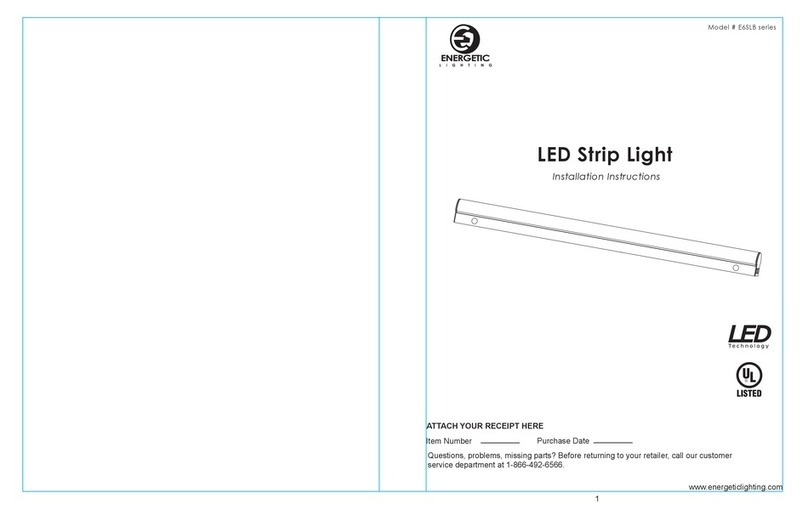
Energetic E5SLB Series User manual

1
LED Strip Light
Installation Instructions
Model # E5SLB series
Questions, problems, missing parts? Before returning to your retailer, call our customer
service department at 1-866-492-6566.
Item Number Purchase Date
ATTACH YOUR RECEIPT HERE
www.energeticlighting.com

32
Please read and understand this entire manual before attempting to assemble, operate or
install the product. Failure to do so could lead to electric shock, fire or other injuries that
could be hazardous or even fatal.
• Be sure the electricity to the wires you are working on is shut off. Either remove the fuse or
turn off the circuit breaker.
• Changes or modifications not expressly approved by the party responsible for compliance
could void the user’s authority to operate the equipment.
• This product must be installed in accordance with local, state and national electrical codes.
• Installation work shall be completed by a licensed installer that is familiar with the
construction and operations of the product.
CAUTION:
• This product is dimmable with 0-10v dimming systems only.
• Units configured with battery backup systems contain a rechargeable LiFePO4 type battery
and must be recycled or disposed of properly according to local jurisdictions.
NOTICE
• This device complies with Part 15 of the FCC Rules. Operation is subject to the following
two conditions: (1) This device may not cause harmful interference, and (2) this device
must accept any interference received, including interference that may cause undesired
operation.
NOTICE:
• This equipment has been tested and found to comply with the limits for a Class B digital
device, pursuant to part 15 of the FCC Rules. These limits are designed to provide
reasonable protection against harmful interference in a residential installation. This
equipment generates, uses and can radiate radio frequency energy and, if not installed and
used in accordance with the instructions, may cause harmful interference to radio or
television reception, which can be determined by turning the equipment off and on. The
user is encouraged to try to correct the interference by one or more of the following
measures:
- Reorient or relocate the receiving antenna.
- Increase the separation between the equipment and the receiver.
- Connect the equipment into an outlet on a circuit different from that to which the receiver
is connected.
- Consult the dealer or an experienced radio/TV technician for help.
• This Class B digital apparatus complies with Canadian ICES-003.
1. Gently press housing base (B) near one end of the
fixture while pulling the metal part of the LED cover
assembly (A) so that housing separates at the seam
as shown.
www.energeticlighting.com www.energeticlighting.com
Part Item Name Qty.
ALED cover assembly 1
BHousing base 1
PACKAGE CONTENTS
SAFETY INFORMATION
SAFETY INFORMATION
INSTALLATION INSTRUCTIONS
Fig. 1
A
A
AA BB CC
2. There is no need to disconnect the two halves of the
fixture body. Support cables will support the weight of
the LED cover assembly (A) during positioning of the
hosuing base (B) up again the mounting surface.
Fig. 2
HARDWARE CONTENTS
Drywall
Anchor
Qty. 2
Wire Nut
Qty. 5
Wood Screw
Qty. 2
B
Press in
Pull to separate
A
B
B
The below steps outline the surface mounting method, where fixture body is fastened
directly to the mounting surface. Alternate mounting methods are outlined in the steps on
Support cables

4
www.energeticlighting.com www.energeticlighting.com
INSTALLATION INSTRUCTIONS INSTALLATION INSTRUCTIONS
BB
DD DD
Fig. 6
3. Align knockout hole with the supply wire location on
junction box, adjust the fixture to the desired
mounting angle and mark the mounting holes through
the keyhole slots at both ends of the strip fixture
housing base (B).
Fig. 4
AA
4. DRYWALL MOUNTING: If the mounting holes go
through drywall without a stud, drill two small pilot
holes using a 3/16-in. drill bit (not included), and
install drywall anchors (AA) into the holes with a
hammer (not included).
CEILING STUD MOUNTING: If the mounting holes
go through ceiling studs, drill four small pilot holes
using a 5/32-in. drill bit (not included) for the wood
screws (BB).
NOTE: Install Wood screws (BB) but leave about
1/2-in. of space between the screw head and
mounting surface.
Fig. 5
Ceiling Stud
Pilot hole
Drywall Mounting
Ceiling
Stud Mounting
Drywall
5
6b. If the fixture is configured with an emergency
battery back-up system:
Connect neutral supply line to white, and ground
supply line to green. Note that there are two line (hot)
leads, labelled as “switched” and “unswitched”,
ensure that the “unswitched” lead is connected to
constant building power (this lead senses the
presence of a power outage); the “switched” lead is
connected to the hot lead of a wall switch or control
relay to turn fixture off without triggering the EM
battery.
NOTE: Connect the two loose connector leads to
enable the battery backup system.
If 0-10v dimming system is available, connect the
purple and gray wires to the corresponding purple
and gray wires in the building dimming system.
Fig. 8
Mark mounting locations
5. Feed the supply wires from the mounting surface
through the knockout hole on the housing base (B).
Guide the heads of the two wood screws into the
keyhole slots and slide the housing base (B) in the
direction such that the wood screw heads rest over the
narrow part of the keyhole slot. Ensure that the fixture
is supported and tighten the two wood screws (DD)
until the fixture is secured to the mounting surface.
Fig. 7
6a. If the fixture is equipped with an emergency battery
backup system, proceed to step 6b, for fixtures without
the battery backup system, proceed with 6a below:
Connect the fixture wires to the supply wires --
black to black, white to white, and green to
copper/bare. WARNING: If there is no ground supply
wire, stop installation and consult a qualified
electrician.
NOTE: If 0-10v dimming system is available, connect
the purple and gray wires to the corresponding purple
and gray wires in the building dimming system.
Once wire connections are made, secure each with a
wire nut (CC).
B
0-10v Dimming Wires:
Purple and Gray
0-10v Dimming Wires:
Purple and Gray
CC
B
Connect battery enable
connectors together
“Switched” and
“Unswitched” Line
connections
B
7. Tuck all loose wires and cables into the housing base
(B). Gently press housing base (B) near one end of
the fixture while securing the LED cover assembly (A)
until all latches securly engages with the housing
base (B).
Fig. 8
Press in where
all latches engage
B
A

This fixture is warranted to perform free from defects for five (5) years. If it fails to do so, you
may return it with proof of purchase to 13445 12th St., Chino, CA 91710 for replacement.
Clean with a mild, non-abrasive glass cleaner and soft cloth. Do NOT use solvents or clean-
ers containing abrasive agents. When cleaning the fixture, make sure the power is turned
off, and any liquid spray should be applied to the cleaning cloth and not sprayed directly onto
the fixture itself.
CARE AND MAINTENANCE
TROUBLESHOOTING
WARRANTY
Problem Possible Solution Corrective Action
Fixture does not light.
Circuit breaker trips
when light is turned on.
1. Power is off.
2. Incorrect wire connection.
3. Defective wall switch.
Crossed wires or power
wire is grounded out.
Verify wires are correctly
connected.
1. Check circuit breaker
or wall switch.
2. Check wire splices.
3. Replace switch.
Printed in China
www.energeticlighting.com
6
www.energeticlighting.com
INSTALLATION INSTRUCTIONS
A. Two slots on both ends of the fixture base (B) can be
used to suspend the fixture using the optional hook
and chain kit. Insert the “S” hook into the slots as
shown, and suspend the other end of the chain to a
secure hook location, or use the provided hooks after
screwing into a wood mounting surface.
Alternate Mounting Method A: Chain suspension
Alternate Mounting Method B: Snap clips
Alternate Mounting Method C: Junction Box Cover Plate
Fig. A
B. Align the junction box supply wires to the intended
knockout location on the housing base (B), mark off
the two locations where the mounting clips should be
mounted to the surface to the respective catch
locations. Secure the two mounting clips to the
intended surface using the supplied wood screws and
anchor (if necessary). Snap the fixture body to the
mounting clips to secure the fixture and complete the
wiring as needed in the prior steps above.
Fig. B
7
C. If the width of the fixture body fails to cover the
junction box opening, a junction box cover plate can
be used between the fixture and junction box. Mount
the JBox cover plate (DD) over the junction box in the
intended mounting surface, using the included
screws. Ensure that all supply wires have been
routed through the center opening.
Fig. C
DD
B
Mounting
clips
Clip engagement
locations
Other Energetic Lighting Equipment manuals
Popular Lighting Equipment manuals by other brands

Schwaiger
Schwaiger WALED 10 Operating and safety instructions
Lightolier
Lightolier F7000-9 Specification sheet
Federal Signal Corporation
Federal Signal Corporation SIGNALMASTER SM518A instruction sheet

MCi
MCi 102D Series Maintenance manual
Qtx
Qtx LED DERBY III user manual
Ignis Pixel
Ignis Pixel BubblePoi 16 manual
