MCi 102D Series User manual

102D SERIES MAINTENANCE MANUAL
01-FRONT AXLE
1BĆ1 Page
August 2000 Date
SECTION 1B
FRONT AXLE 16,000 LBS GA R
CONTENTS OF THIS SECTION
SUBJECT PAGE
General Description 1BĆ1. . . . . . . . . . . . . . . . . . . . . . . . . . . . . . . . . . . . . . . . . . . . . . .
Components 1BĆ1. . . . . . . . . . . . . . . . . . . . . . . . . . . . . . . . . . . . . . . . . . . . . . . . . . . . .
Maintenance 1BĆ3. . . . . . . . . . . . . . . . . . . . . . . . . . . . . . . . . . . . . . . . . . . . . . . . . . . . .
Lubrication 1BĆ20. . . . . . . . . . . . . . . . . . . . . . . . . . . . . . . . . . . . . . . . . . . . . . . . . . . . . . .
Troubleshooting 1BĆ23. . . . . . . . . . . . . . . . . . . . . . . . . . . . . . . . . . . . . . . . . . . . . . . . . .
Speci ications 1BĆ27. . . . . . . . . . . . . . . . . . . . . . . . . . . . . . . . . . . . . . . . . . . . . . . . . . . .
Fastener Torque Chart 1BĆ28. . . . . . . . . . . . . . . . . . . . . . . . . . . . . . . . . . . . . . . . . . . . .
Service Tools 1BĆ30. . . . . . . . . . . . . . . . . . . . . . . . . . . . . . . . . . . . . . . . . . . . . . . . . . . . .
GENERAL DESCRIPTION
The ront and trailing axle assemblies are drop center
cast or orged beam design with orged steel knuckle pin
ends (Figure 1). Knuckle pin ends are integral parts o the
axle center beam.
Steering knuckles have grease ittings in both knuckle
pin bosses or lubrication o the knuckle bushings. The
bushings are o the Easy Steer" type. Covers and plugs
prevent dust and moisture rom entering bushings and
serve as seals.
Identification
The axle model number identi ication plate is on the
axle center. Use the model number to order the correct
parts (Figure 2).
COMPONENTS
Axle Beam
ARNING
Do not attempt to straighten the axle. Any
manipulation or straightening of the axle could
severely reduce load rating and driveability.
The axle beam is cast or orged. The other axle
components assemble to this part.
Tie rod assembly
The tie rod assembly attaches to the tie rod arm, and to
the axle through the steering arm and knuckles. It
maintains the correct steering geometry. The tie rod
assembly has an adjustable center section and sealed
replaceable ball joint ends.
Knuckle ends
Steering knuckles are attached to the axle ends with
straight king pins and are retained by a set o draw keys.
Knuckles are itted with special king pin bushings. King
pin bushing covers, spacers and seals prevent dust and
moisture rom entering the bushings.
Stop screws installed on each knuckle assembly limit
the wheels' turning angle. Knuckles mount all steering
and wheel end components: tie rod arms, brakes and
wheel bearings and hubs).

102D SERIES MAINTENANCE MANUAL
01-FRONT AXLE
1BĆ2 Page
August 2000 Date
Figure 1. Front Axle Assembly (16,000 lbs.)
Tie Rod
Tie Rod Arm
Tie Rod Arm
Steering Arm
King Pin
Axle
Q Plus Cam Brake
(Refer to Sect. 4C1)
Brake Drum
Grease Fitting
Grease Fitting
Shims
Bearing
Bushing
Bushing
Steering Knuckle
Threaded King Pin Cap

102D SERIES MAINTENANCE MANUAL
01-FRONT AXLE
1BĆ3 Page
August 2000 Date
FIGURE 2. Axle identification
MAINTENANCE
TIE ROD INSPECTION
Proper tie rod end inspection and replacement is an
important part o maintaining proper vehicle alignment.
Replacement o worn tie rod end will prevent premature
wear o other steering and suspension components and
will help to ensure smooth, precise steering and control.
Adhere to the ollowing procedure when per orming
regular tie rod end inspections:
Note: Tie rod end inspections should always be
performed prior to lubrication. If the inspection is
performed after lubrication, there may be a false
indication that the tie rod end is fully operative.
ă1.ăPark the vehicle with the wheels in the straight
ahead" position, then turn the vehicle o .
ă2.ăPlace blocks in ront o and behind the ront and
rear tires to prevent the vehicle rom moving.
ă3.ăTo inspect the tie rod end, care ully remove all dirt
and grease rom the seal o the tie rod end. Examine the
seal or any indication o damage such as slits, tears, etc.
I the seal utilizes a retention ring on the socket, inspect
the ring or damage.
Note: If the seal is damaged or the ring is missing,
replace the tie rod end as soon as possible.
ă4.ăI the seal and ring are acceptable, try to move the
tie rod cross tube by hand (Figure 3). I movement or
looseness is detected, set up a dial indicator, (as shown in
Figures 4 and 5).
Figure 3
CAUTION
Do not use a pry bar or other mechanical
method on the steering linkage, this could result
in damage to the tie rod end and/or create a false
indication of wear.
ă5.ăThere are two separate methods that can be used
to check the degree o movement in the tie rod end:
Figure 4
a. To check axial (up and down) movement, set
the dial indicator so that the base o the indicator is on the
tie rod arm. Then, place the tip o the indicator on the
bottom o the tie rod end at the area that it is most
lat.(Figure 4)

102D SERIES MAINTENANCE MANUAL
01-FRONT AXLE
1BĆ4 Page
August 2000 Date
Figure 5
b. To check radial (back and orth) movement, set
the dial indicator so that the base o the indicator is on the
tie rod arm. Then, place the tip o the indicator on the
socket o the tie rod end. Be sure to position the dial
indicator so that it is line with the direction o movement.
(Figure 5)
ă6.ăSet the dial indicator to 0" (zero).
ă7.ăMove the cross tube assembly up and down or
back and orth, depending on which direction you are
checking or looseness. I the indicator reading is 0.060"
or more, replace the tie rod end immediately. I the
indicator reading is above 0.030", it should be replaced at
the next service interval.
CAUTION
Do not remove the tie rod end from the tie rod
arm to check for ball stud rotating torque. This
may damage the seal if a removal tool is used.
Additionally, the tie rod end seal can cause false
indications of internal torque.
ă8.ăRepeat steps three (3) through seven (7) or the
other tie rod end.
Note: hen one tie rod end requires replacement,
it is recommended to replace both to allow for even
wear on both sides of the vehicle.
REMOVAL AND DISASSEMBLY
Tie rod, tie rod arms and tie rod ends
ARNING
To prevent serious eye injury, always wear safe
eye protection when you perform vehicle
maintenance or service.
ARNING
Support the vehicle with safety stands. Do not
work under a vehicle supported only with jacks;
jacks can slip or fall over and cause serious
personal injury or death.
ă1.ăMake sure the vehicle is on a level sur ace.
ă2.ăSet the park brake.
ă3.ăPlace blocks under the wheels not being serviced
to prevent the vehicle rom moving.
ă4.ăRaise the vehicle so that the wheels to be serviced
are o the ground. Support the vehicle with sa ety stands.
ă5.ăRemove the cotter pins that asten each tie rod ball
joint to the tie rod arms (Figure 6).
Figure 6.ăTie rod end and arm
ă6.ăDisconnect the tie rod assembly rom the tie rod
arm. You might have to use a removal tool to separate the
tie rod ball joint rom the tie rod arm.
ă7.ăRemove the cotter pin and nut that asten the tie
rod arms in the knuckle.

102D SERIES MAINTENANCE MANUAL
01-FRONT AXLE
1BĆ5 Page
August 2000 Date
ă8.ăRemove the tie rod arms rom the knuckle. You
may have to tap on the end o the arm with a leather or
plastic mallet to separate the arm rom the knuckle.
Remove the key rom the tie rod arm.
FIGURE 7. Removing rod ends
ă9.ăI necessary, remove the tie rod ends rom the tie
rod according to the ollowing procedure:
a. Mark the position where each tie rod end is
installed in the tie rod (Figure 7). (The position o tie rod
ends determines toeĆin).
b. Remove the bolts and nuts rom the clamp on
the tie rod.
c. Remove the tie rod ends rom the tie rod.
NOTE: It is imperative to per orm a ront end alignment
to reset the toeĆin a ter tie rod ends are replaced (Re er
to Sect. 2C Alignment Procedure").
Removing the knuckle
A. Preparation
ă1.ăSet the park brake.
ă2.ăBlock the axle and coach body.
ă3.ăRemove the air rom the brake system and
disconnect the air lines rom the brakes.
ă4.ăRemove the wheel and tire assembly. (See the
Operator's manual or this procedure).
B. Hub removal
ă1.ăRemove the brake drum.
ă2.ăRemove the hub (Figure 8).
FIGURE 8. Removing cap and gasket
CAUTION
hen tightening or loosening the adjusting nuts
for the wheel bearing, always use the
correctĆsized socket, to avoid damaging the
adjusting nut.
ă3.ăBend the lock washer tabs o the jam nut and
remove the jam nut, jam nut lock washer, pierced lock
ring and adjusting nut rom the knuckle Figure 8).
ă4.ăRemove the air rom the brake system and
disconnect the air lines rom the brake chambers.
ă5.ăRemove the caliper rom the torque plate per the
manu acturer's procedure.
ă6.ăRemove the outer wheel bearing cone rom the
hub.
ă7.ăRemove the hub.
C. Knuckle removal
ă1.ăRemove the torque plate rom the knuckle.
ă2.ăRemove the tie rod arms and steer arm rom the
knuckle per the previous procedure in this manual.
ă3.ăUnscrew the king pin caps rom the top and
bottom o the knuckle.
ă4.ăRemove the threaded draw keys rom the beam,
according to the ollowing procedure:
ARNING
Do not hit steel parts with a steel hammer. The
parts can break and cause serious personal
injury.

102D SERIES MAINTENANCE MANUAL
01-FRONT AXLE
1BĆ6 Page
August 2000 Date
CAUTION
Apply force directly to the bottom of the nut and
the end of the key. Otherwise, the draw key will
be damaged.
FIGURE 9. Loosening the draw key
a. Loosen the lock nut and move the lock nut end
to the the end o the threads. Make sure the top o the lock
nut is even with the end o the draw key.
b. Use a brass dri t and hammer to hit the end o
the nut to loosen the draw key (Figure 9).
c. Remove the nut and draw key rom the beam.
CAUTION
If you are not replacing the bushings, do the
following to prevent damage to the bushings
while removing the king pins:
1. Remove any flaring on the drift that may touch
the king pin.
2. rap tape to a thickness of 0.0625 inch (1.5
mm) on the end of the drift.
ARNING
Obey all the press manufacturer's warnings and
cautions regarding the press operation, to avoid
serious personal injury and possible
component damage.
ă5.ăUse a brass dri t and hammer (Figure 10) to
remove the king pins rom the knuckle. I the king pin is
di icult to remove, use a hydraulic king pin remover. (See
the Service Tools subsection at the end o this document).
Figure 10.ăKing Pin Removal
ă6.ăRemove the knuckle rom the axle center beam.
ă7.ăRemove the shims, thrust bearing and seal rom
the knuckle (Figure 11).
FIGURE 11. Removing thrust bearing
ă8.ăI the knuckle bushings are damaged, remove the
bushings according to the ollowing procedure:
a. Remove and discard the upper and lower king
pin seals (Figure 12).

102D SERIES MAINTENANCE MANUAL
01-FRONT AXLE
1BĆ7 Page
August 2000 Date
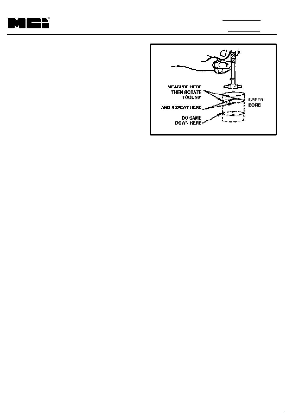
FIGURE 12. Removing king pin seals
b. Make a tool to remove the bushings. See
Service Tools" later in this section or the tool
dimensions.
c. Put the knuckle on the press.
NOTE: Use a press with a 5 ton (4545 kg) capacity,
and make sure the knuckle does not move when the
bushings are removed.
d. Install the tool in the upper king pin bushing.
e. Press the top bushing rom the knuckle (Figure
13).
FIGURE 13. Bushing removal
. Install the tool in the lower king pin bushing.
g. Press the bottom bushing rom the knuckle
(Figure 13).
REPAIRING PARTS
ARNING
To prevent serious eye injury, always wear safe
eye protection when you perform vehicle
maintenance or service.
Repairing or reconditioning ront and trailing axle parts
is prohibited. The axle manu acturer recommends
replacing damaged or outĆo Ć speci ication components.
All major components are heatĆtreated and tempered.
The components cannot be bent, welded, heated or
repaired in any way without reducing the strength or li e o
the component.
The ollowing operations are prohibited on ront axle
components:
ă1.ăWelding o or to steering arms, tie rod arms,
knuckles, king pins, axle centers, tie rod assemblies,
hubs, drums, or brakes.
ă2.ăHot or cold bending o knuckles, steering arms, tie
rod arms, ball studs, axle centers or tie rod assemblies.
ă3.ăDrilling out o holes in the axle center beam or
knuckle pins.
ă4.ăDrilling out o draw key holes in the axle center
beam.
ă5.ăSpray welding o bearing diameters on knuckles
or in machined bores.
ă6.ăMilling or machining o any component.
ARNING
If you use cleaning solvents, hot solution tanks
or alkaline solutions incorrectly, injury can
occur. To prevent injury, follow the
manufacturer's instructions. DO NOT use
gasoline to clean parts; gasoline can explode.
Cleaning ground or polished parts
Use cleaning solvent to clean ground or polished parts
and sur aces. Kerosene and diesel uel can be used or
this purpose. DO NOT use gasoline.
CAUTION
DO NOT clean ground or polished parts in a hot
solution tank or with water, steam, or alkaline
solutions. These solutions will cause the parts
to corrode.
Cleaning rough parts
Rough parts can be cleaned with the ground or
polished parts. Rough parts can also be cleaned in hot

102D SERIES MAINTENANCE MANUAL
01-FRONT AXLE
1BĆ8 Page
August 2000 Date
solution tanks with a weak alkaline solution. The parts
must stay in the hot solution tanks until they are
completely cleaned and heated.
Drying cleaned parts
Parts must be dried immediately a ter cleaning. Dry the
parts with clean paper or rags, or with compressed air. Do
not dry bearings by spinning them with compressed air.
Preventing corrosion on cleaned parts
Apply light oil to cleaned and dried parts that are not
damaged and are to be immediately assembled. DO NOT
apply oil to brake linings.
I the parts are to be stored, apply a good corrosion
preventative to all sur aces. DO NOT apply this material to
brake linings.
Store the parts in special paper or another material that
prevents corrosion.
NOTE: make sure all tapered parts are clean and dry,
with no lubricant or corrosion preventative applied to
mating sur aces.
INSPECTING PARTS
Care ully inspect any disassembled parts be ore
reusing them. Re er to the ollowing guidelines:
ă1.ăInspect and replace any parts that are worn,
cracked, or damaged. Check or cracks using dye
penetrant, magnetic lux, or lourescent particle testing
methods.
ă2.ăMeasure the king pin bushing inside diameter
using a micrometer and telescoping gauge or taking
measurements (Figure 14).
FIGURE 14. Bushing measurement
I the average inside diameter measurement is greater
than the king pin bushing maximum inner diameter in
Table 1 below, install new bushings.
ă3.ăA ter removing a worn bushing, measure the
knuckle bore inside diameter in two locations. Always use
a micrometer and telescoping gauge when taking
knuckle bore measurements. Some rounding o the top
and bottom bore edges is acceptable.
Measure the bore in our positions and at two
locations. The two locations must be 90° opposed to
each other. I the average measurement is greater than
the knuckle bore maximum diameter speci ication in
Table 1, replace the knuckle (Figure 15).

102D SERIES MAINTENANCE MANUAL
01-FRONT AXLE
1BĆ9 Page
August 2000 Date
Table 1
Axle ear Limit Specifications
Knuckle bore: maximum
diameter inches (mm)
Beam bore: maximum
diameter inches (mm)
Knuckle bushing bore: maximum
diameter inches (mm)
1.922 (48.818) 1.7980 (45.6692) 1.796 (45.618)
FIGURE 15. Knuckle measurement
Follow this procedure or both the upper and lower
knuckle bores. I either bore's diameter exceeds the limits
in Table 1, remove and replace the knuckle.
ă4.ăMeasure the inner bore diameter o the axle beam.
Rounding at the top and bottom o the beam is
acceptable.
Measure the axle beam bore at our positions, and at
two speci ic locations: 0.5 inch (12.7 mm) below the top o
the bore, and 0.5 inch (12.7 mm) above the bottom o the
bore (Figure 16).
FIGURE 16. Axle beam measurement
I the average measurement is greater than the axle
beam bore maximum diameter shown in Table 1 below,
the axle beam requires replacement.
ă5.ăInspect the taper on the tie rod arm or wear or
damage.
ă6.ăInspect the hole or taper in the knuckle. I the hole
is worn or damaged, replace the knuckle and arm. I only
the taper on the arm is damaged, replace the arm.
ă7.ăI the king pin has worn through the bushing and
into the knuckle, replace the knuckle.
NOTE: I any part o the linkage is loose, check all the
pivot points. Check the pivot points when the linkage is
lubricated.
ă8.ăMake sure all pivot points in the steering linkage
are tight.
ă9.ăInspect the thrust bearing and seal or wear or
damage. Replace parts that are worn or damaged.
Tie rods and tie rod ends
ă1.ăInspect the tie rod or wear and damage. Replace
the tube it i it is worn or damaged.
CAUTION
DO NOT repair tie rods.
ă2.ăInspect the tie rod end or wear and damage.
Replace it i it is worn or damaged. For more details, see
the troubleshooting subsection.
ă3.ăI a seal is damaged on tie rod ends with a grease
itting, replace only the seal. I the tie rod end does not
have a itting, replace the complete tie rod end.
heel bearings
ă1.ăInspect the wheel bearings when the knuckle is
inspected or repaired.
ă2.ăRemove all lubricant rom the bearings, knuckle,
hub, and hub cap.
ă3.ăInspect the cup, the cone and the rollers and cage
o all bearings. I any o the ollowing conditions exist,
replace the bearing:

102D SERIES MAINTENANCE MANUAL
01-FRONT AXLE
1BĆ10 Page
August 2000 Date
FIGURE 17. ear indicators
a. The center o the large diameter end o the
rollers is worn level or below the other sur ace (Figure
17).
b. The radius at the large diameter end o the
rollers is worn to a sharp edge (Figure 17).
c. A visible groove in the cup or the cone inner
race sur aces. The groove can be seen at the small or
large diameter end o both parts (Figure 18).
FIGURE 18. Race surface wear indicators
d. Deep cracks or breaks in the cup, the cone
inner race, or the roller sur aces (Figure 18).
e. Bright wear marks on the outer sur ace o the
roller cage (Figure 19).
FIGURE 19. Roller cage wear indicators
. Damage on the rollers and on the sur aces o the
cup and cone inner race that touch the rollers (Figure
20).
FIGURE 20. Cup and cone wear indicators
g. Damage on the cup and cone inner sur aces
that touch the rollers (Figure 21).
FIGURE 21. Cup and cone wear indicators

102D SERIES MAINTENANCE MANUAL
01-FRONT AXLE
1BĆ11 Page
August 2000 Date
ASSEMBLY AND INSTALLATION
ARNING
To prevent a serious eye injury, always wear safe
eye protection when you perform vehicle
maintenance or service.
ARNING
Obey all the press manufacturer's warnings and
cautions concerning press operation, to avoid
serious personal injury and possible damage to
components.
Installing bushings
ă1.ăInstall the top knuckle bushing irst.
ă2.ăPlace the spindle in a press so that the bores or
the bushings are straight. The upper knuckle boss must
be toward the top o the press.
ă3.ăPlace the bushing in the bore.
ă4.ăUse the installation tool to press the bushing 0.125
inch (3 mm) into the bore. Release the pressure on the
press and make sure the bushing is being pressed
straight into the bore (Figure 22).
FIGURE 22. Bushing installation
ă5.ăPress the bushing into the bore until the bottom o
the bushing is 0.148 to 0.178 inch (3.75 to 4.52 mm)
above the bottom o the knuckle bore (Figure 23).
FIGURE 23. Bushing installation depth
ă6.ăTurn the knuckle over so that its bottom is toward
the top o the press. Make sure the bore or the bushing is
straight.
ă7.ăPlace the bottom o the bushing in the bore.
ă8.ăUse the installation tool to press the bushing 0.125
inch (3 mm) into the bore. Release the pressure on the
press and make sure the bushing is being pressed
straight into the bore (Figure 22).
ă9.ăPress the bushing into the bore until the bottom o
the bushing is 0.148 to 0.178 inch (3.75 to 4.52 mm)
above the bottom o the knuckle bore (Figure 23).
ă10.ăReam the bushing according the the procedure
later in this subsection.
Reaming knuckle bushings
CAUTION
Reaming with a fixed reamer is the only
recommended procedure. Do not hone or
burnish the bushings, because honing or
burnishing will damage them.
ă1.ăPut the spindle in a vise with brass jaws.
ă2.ăMake a reamer tool. (See the Service tools
subsection at the end o this section).
ă3.ăSlide the pilot o the reamer tool through the top
bushing in the knuckle until the reamer blades touch the
bushing (Figure 24).

102D SERIES MAINTENANCE MANUAL
01-FRONT AXLE
1BĆ12 Page
August 2000 Date
Figure 24. Reaming the bushing
ă4.ăRotate the reamer tool with slight downward
pressure; do not apply too much orce. Rotate the reamer
tool smoothly.
ă5.ăA ter the reamer has cut through most o the top
bushing, support the tool so it does not drop to the
bottom bushing
ă6.ăA ter cutting the top bushing, guide the reamer
tool into the bottom bushing. Repeat steps 3 to 5 or the
bottom bushing (FIgure 25).
Figure 25.ăReaming the Lower Bushing
REAM LO ER
BUSHING SECOND
(PUSH DO N LIGHTLY)
ă7.ăSlide the reamer tool out the bottom o the bottom
bushing.
NOTE: I you must remove the reaming tool through
the top o the bushing, rotate the tool in the opposite
direction as you remove it.
ă8.ăClean all material rom the bushings, knuckle, and
king pin cap threads.
Installing the inner knuckle bushing seal
ă1.ăPlace the knuckle in a vise with brass jaws, so that
the vise jaws hold the top o the knuckle. The bottom o
the knuckle must be toward you.
ă2.ăPlace the seal in the bottom o the knuckle bore.
Make sure the lip seal is away rom the bore (Figure 26).
Figure 26.ăGrease Seal Installation
ARNING
Do not hit steel parts with a steel hammer. The
parts can break and cause serious personal
injury.

102D SERIES MAINTENANCE MANUAL
01-FRONT AXLE
1BĆ13 Page
August 2000 Date
ă3.ăUse a brass dri t, a hammer, and the correct size
driver or socket to install the seal. Install the seal until the
top o the seal is even with the knuckle's machined
sur ace (Figure 26).
ă4.ăTurn the knuckle over in the vise. The jaws o the
vise must hold the bottom o the knuckle. The top o the
knuckle must be toward you.
ă5.ăPlace the seal in top o the bottom knuckle bore.
Make sure the lip o the seal is away rom the bore.
ă6.ăRepeat Step 3 o this procedure.
Installing a knuckle
ă1.ăClean the bores o he knuckle and axle center.
ă2.ăPlace the knuckle on the axle center.
NOTE: Some newer thrust bearings have the seal
integrated with the bearing assembly (Figure 27).
FIGURE 27. Bearing with integrated seal
The oneĆpiece thrust bearing with integrated grease
seal is completely interchangeable with the twoĆpiece
design. It has a speci ied top and bottom orientation:
The sur ace with the inner diameter seal must be on
top.
The sur ace with the outer diameter seal must be on
the bottom (Figure 27).
ă3.ăOn cover" type seals, install the cover seal over
the open part o the thrust bearing (Figure 28).
Figure 28.ăBearing And Seal Assembly
ă4.ăSlide the seal and thrust bearing between the
bottom o the axle center and the knuckle. Make sure the
seal is toward the axle center and over the thrust bearing
(Figure 29).
Figure 29.ă Knuckle & Seal Installation
ARNING
ear gloves when holding shims. Shims have a
sharp edge and can cause serious personal
injury.
ă5.ăInstall shims according to the ollowing
procedure:
a. Inspect the shims and replace any damaged
ones.

102D SERIES MAINTENANCE MANUAL
01-FRONT AXLE
1BĆ14 Page
August 2000 Date
b. I a new shim pack must be used, select the
amount o shims that will give the least end play: 0.001
inch minimum to 0.025 inch maximum (0.025 mm to
0.635 mm).
c. Place a pry bar between the steering arm boss
and the axle beam. Li t the knuckle and slide the shim
pack between the top o the axle and the knuckle (Figure
30).
FIGURE 30. Adding a shim
d. Make sure to align the bores o the knuckle,
axle center, shims, seals, and thrust bearing. I these
parts are not aligned, installing the king pin will damage
parts.
e. Remove the pry bar.
ă6.ăInstall the king pin according to the ollowing
procedure (Figure 31):
a. Apply the speci ied lubricant to the bottom hal
o the king pin.
b. Install the king pin in the top o the knuckle.
Make sure the word TOP" that is stamped on the king pin
is toward you.
FIGURE 31. Installing the king pin
c. Rotate the king pin to that the draw key slots in
the pin are aligned with the holes in the axle center.
CAUTION
Do not force the pin through the top bushing,
because this will damage the shims.
d. Push the king pin through the top bushing,
bushing seal and shim pack. I the pin is di icult to install,
make sure all parts are aligned properly.
e. A ter the king pin is through the shim pack,
push the king pin into the bottom bushing. I necessary,
use a brass hammer to drive the king pin into the bushing.
Make sure the axle center, spindle and thrust bearing and
the bushing seal are aligned.
. Make sure the draw key slots in the king pin are
aligned with the holes in the axle center.

102D SERIES MAINTENANCE MANUAL
01-FRONT AXLE
1BĆ15 Page
August 2000 Date
NOTE: Do not drive the draw keys into the knuckle
until a ter the end play is checked and adjusted.
Figure 32.ăSeating Draw Keys
ă7.ăInstall the top draw key in ront o the axle center.
Install the bottom o the draw key behind the axle center.
Make sure the key goes through the slot in the pin. Lightly
tap the draw keys into the axle center (Figure 32).
ă8.ăCheck the knuckle's end play according to one o
the ollowing procedures:
Procedure 1: Checking end play with the wheel not
installed on the spindle
a. Hit the top boss o the knuckle with a rubber
mallet to move all parts in position.
b. Turn the knuckle to the straight ( orward)
position.
c. Attach a dial indicator: Put the indicator's base
on the knuckle assembly. Put the indicator's tip on the
center o the king pin. Move the dial indicator to the zero"
position (Figure 33).
Figure 33.ăDial Indicator Installation
MAGNETIC BASE
LOCATED AT EITHER
PLACE
d. Use one o the ollowing procedures to
measure end play:
Put a pry bar between the knuckle and the top o the
axle center. Put the knuckle upward and measure the end
play (Figure 34).
Figure 34.ăMeasuring End Play
ARNING
If you are using a hydraulic jack to measure end
play, use safety stands to support the axle.
Otherwise the axle can fall and cause serious
personal injury.

102D SERIES MAINTENANCE MANUAL
01-FRONT AXLE
1BĆ16 Page
August 2000 Date
Put a block o wood and a hydraulic jack under the
bottom o the knuckle. Raise the knuckle until the pointer
on the dial indicator stops (Figure 35).
Figure 35.ăJacking a Knuckle
HARD
OOD BLOCK
e. Repeat steps b. and c. with the axle in ull right
turn and ull le t turn positions.
. The end play must measure between 0.001 and
0.025 inch (p.025 to 0.635 mm) in all axle positions.
I the knuckle binds or the end play is zero, remove
some shim rom the pack.
I the end play measures more than 0.025 inch (.635
mm) add shims to the pack.
Procedure 2: Checking end play with the wheel
installed on the vehicle
a. Install a dial indicator: make sure the indicator's
base in on the axle center. Make sure the indicator's tip is
on the center o the knuckle cap. The indicator's tip can
also be put on the knuckle (Figure 36).
Figure 36.ăDial Indicator Positioned
b. Use a lever to li t the knuckle to measure the
end play.
c. The end play must measure between 0.001 and
0.025 inch (p.025 to 0.635 mm) in all axle positions.
I the knuckle binds or the end play is zero, remove
some shim rom the pack.
I the end play measures more than 0.025 inch (.635
mm) add shims to the pack.
CAUTION
Make sure the draw key is installed completely
and the locknut is tightened to the specified
torque. If the draw key is not installed correctly,
the king pin and axle center will be damaged.
ă9.ăInstall the lock nut on the threaded draw keys and
tighten them to 30 to 45 lbĆ t (41 to 54 NĆm) (Figure 37).

102D SERIES MAINTENANCE MANUAL
01-FRONT AXLE
1BĆ17 Page
August 2000 Date
FIGURE 37. Tightening threaded keys
ă10.ăApply sealant 360o around the irst thread o the
king pin cap and install the top and bottom threaded king
pin caps (Figure 38). Tighten the caps to 100 to 120 t.Ćlb
(135 to 160 NĆm).
FIGURE 38. Tightening king pin caps
ă11.ăConnect the tie rod arm to the knuckle. See the
procedure in this subsection or the correct method.
ă12.ăInstall the torque plate on the knuckle.
ă13.ăInstall the hub and rotor assembly on the
knuckle.
ă14.ăInstall the outer wheel bearing cone in the hub.
ă15.ăAdjust the wheel bearings. See the ollowing
subsection, titled Adjustments."
ă16.ăInstall the hub and gasket on the knuckle. Install
the capscrews and tighten them to 20 to 30 lbĆ t (27 to 41
NĆm). Tighten the plastic hub caps to 12 to 16 lbĆ t (16 to
22 NĆm).
ă17.ăAdd oil to the hub to the proper level. See the
subsection titled Lubrication" later in this section.
ă18.ăReconnect the brake lines.
ă19.ăInstall the tire and wheel assembly.
ă20.ăLower the vehicle to the ground. Check the brake
operation.
ă21.ăCheck and adjust the toeĆin. See the subsection
titled Adjustments" later in this subsection.
Install tie rod arms and steering arms
ă1.ăInstall the key in the slot at the tapered end o the
arm: press the key into the slot.
NOTE: Do not mix arm key and slot types. The square
key is positioned lush to the shoulder o the arm taper.
The woodru key is positioned in the slot provided.
ă2.ăInstall the tie rod arm in the knuckle.
CAUTION
Tighten the nuts of the tie rod arm to the
specified torque. Failing to use the proper toque
will damage the tie rod arm, Pitman arm, or
knuckle.
ă3.ăInstall the nut that astens the tie rod arm or
steering arm to the knuckle:
For 1.125Ć12 thread, tighten the nut to 550 to 1025 lbĆ t
(745 to 1388 NĆm).
For 1.25Ć12 thread, tighten to 777 to 1450 lbĆ t (1051 to
1965 NĆm).
ă4.ăInstall the cotter pins. I the holes are not aligned,
tighten the nut to the next hole in the nut.
NOTE: Do not loosen nuts to install the cotter pin.
ă5.ăCheck and, i necessary, adjust the toeĆin. See the
subsection titled Adjustments" later in this section.
Install the tie rod assembly and tie rod ends
See Figure 39 below.

102D SERIES MAINTENANCE MANUAL
01-FRONT AXLE
1BĆ18 Page
August 2000 Date
FIGURE 39. Tie rod assembly and ends
NOTE: The tie rod has rightĆhand threads on one end
and le t hand threads on the other. Make sure to install
the correct tie rod ends on the tie rod.
ă1.ăI they have been removed, install the tie rod ends
on the tie rod. Install the tie rod ends to the positions
marked during their removal.
I new tie rod ends are installed, thread the tie rod ends
equally on each side o the tie rod to the overall required
length.
ă2.ăInstall nuts and bolts in clamps on the tie rod.
Tighten the nuts and bolts to 40 to 60 lbĆ t (55 to 82 NĆm).
ă3.ăClean and dry the tie rod taper and tie rod arm
taper hole.
ă4.ăConnect the tie rod ends into the tie rod arms on
the knuckle.
ă5.ăInstall the nuts that asten the tie rod ends to the tie
rod arms. Tighten the nuts to 160 to 300 lbĆ t (217 to 406
NĆm).
ă6.ăInstall the cotter pins. I the holes are not aligned,
tighten the nut to the next hole.
NOTE: Do not loosen nuts to install the cotter pin.
ă7.ăCheck and, i necessary, adjust the toeĆin. See the
subsection titled Adjustments" later in this section.
ADJUSTMENTS
heel bearings
ARNING
Support the vehicle with safety stands. Do not
work under a vehicle supported only with jacks;
jacks can slip or fall over and cause serious
personal injury or death.
Preparation
ă1.ăMake sure the vehicle is on a level sur ace.
ă2.ăPlace blocks under the wheels not being serviced
to keep the vehicle rom moving.
ă3.ăRaise the vehicle so that the wheels to be serviced
are o the ground. Support the vehicle with sa ety stands.
NOTE: I you are using oil lube hubs, drain all oil rom
the hubcap.
ă4.ăRemove the wheel and tire assembly rom the
hub.
ă5.ăRemove the capscrews that asten the cap to the
hub.
ă6.ăBack o the disc brake caliper adjustment and
remove the disc brake pads rom the caliper to allow
accurate measurement. (See Section 4C or the pad
removal procedure).
Adjustment
ă1.ăAttach a dial indicator with the magnetic base at
the bottom o the hub.
Adjust the dial indicator so that the pointer is against
the center o the spindle. Set the dial indicator to zero
(Figure 40).
FIGURE 40. Setting the dial indicator
NOTE: Do not push or pull at the top and bottom o the
hub. Doing this will not give a true reading o the end
play.

102D SERIES MAINTENANCE MANUAL
01-FRONT AXLE
1BĆ19 Page
August 2000 Date
ă2.ăMeasure the end play by pushing or pulling on
each side o the hub while looking at the dial indicator.
The end play is the total travel observed. I the end play is
not within 0.001 to 0.005 inch (0.025 to 0.127 mm) adjust
the wheel bearings.
ă3.ăI necessary, adjust the wheel bearings according
to the procedure in Step 7.
ă4.ăBend the lock washer o the lats o the jam nut
and remove the jam nut, jam nut washer and pierced lock
ring.
NOTE: When removing or installing adjusting nuts,
use the correct wrench socket to avoid damaging the
nuts.
CAUTION
Do not strike the adjusting nut with a metal
hammer and do not use a hammer and chisel or
drift to loosen the adjusting nut. This will
damage the nut.
ă5.ăUse a torque wrench to tighten the adjusting nut to
100 lbĆ t (136 NĆm) while rotating the hub in both
directions.
ă6.ăLoosen the nut completely and then tighten it to 20
lbĆ t (27 NĆm) while rotating the hub.
ă7.ăAdjust the wheel bearing according to the
ollowing procedure (Figure 41):
FIGURE 41. heel bearing adjustment
a. Back o the adjusting nut 1/3 turn.
b. Install the pierced lock ring, lock washer, and
jam nut.
c. For the 1 1/8Ć2 5/8 inch threaded jam nut, tighten
it to 200 to 300 lbĆ t (271 to 407 NĆm).
d. Measure the wheel end play to maker sure the
end play is between 0.001 to 0.005 inch (0.025 to 0.127
mm). I not, repeat Steps a. to c. I the end play exceeds
0.005 inch (0.127 mm) reduce the amount the adjusting
nut is backed o in Step a. to 1/4 turn.
e. When the proper play is achieved, lock the jam
nut in place by bending the edge o the jam nut lock
washer over one lat o the jam nut.
ă8.ăMeasure the end play by pushing or pulling on the
horizontal axis o the hub while watching the dial indicator.
The end play is the total travel observed. I the end play is
not within speci ications, adjust the wheel bearings.
ă9.ăInstall the gasket and cap on the hub. Install the
capscrews and tighten them to 20 to 30 lbĆ t (27 to 41
NĆm). Tighten the plastic hub caps to 12 to 16 lbĆ t (16 to
22 NĆm).
ă10.ăInstall the tire and wheel assembly.
ă11.ăLower the vehicle to the ground and check the
brake operation.
ă12.ăRe ill the oil lube hub reservoir. (See the
lubrication subsection later in this section.)
Steering stop adjustment
The steering stop adjustment controls the vehicle's
maximum turn angle.
CAUTION
If the stop bolt is missing, bent or broken, the
steering system limiter needs adjustment.
NOTE: I the steering system is out o adjustment,
inspect the steering arm and tie rod arms or damage.
Use a magnetic particle or liquid dye penetrant
inspection procedure to inspect the steering arm. Pay
particular attention to the bend, the taper and the area
near the ball stud.
CAUTION
Do not increase the vehicle's maximum
specified turn angle. If the angle is increased,
the steering arm, tie rod and tie rod ends will be
damaged.
CAUTION
In power steering systems, the hydraulic
pressure should relieve or drop off" at the end
of the steering stroke (with 0.125 inches or 3 mm
minimum clearance at the stop bolt). If the
pressure does not relieve, the axle components
will be damaged.

102D SERIES MAINTENANCE MANUAL
01-FRONT AXLE
1BĆ20 Page
August 2000 Date
NOTE: The stop bolt should NOT touch the beam. it
should always have a minimum clearance o 0.125
inches (3 mm) as shown in Figure 42, below.
FIGURE 42. Minimum stop bolt clearance
ă1.ăPut a 1/8 inch (3 mm) spacer between the stop bolt
and the boss on the axle beam.
ă2.ăTurn the steering wheel until the boss on the axle
beam touches the spacer in ront o the stop bolt.
Measure the angle (Figure 43).
FIGURE 43. Spacer placement
ă3.ăI the maximum angle does not meet
speci ications, correct it. Adjust the pressure relie .
ă4.ăWhen a maximum turn angle is correct (51o or the
ront axle, 11o or the trailing axle):
a. Loosen the stop bolt jam nut (Figure 43).
b. Insert a 1/8 inch (3 mm) spacer and adjust the
stop bolt.
c. Tighten the jam nut to 65 to 85 lbĆ t (68 to 101
NĆm).
Pressure relief adjustment (Setting maximum
turn angle)
The pressure relie in the power steering system stops
or reduces the orces applied to the axle when the wheel
is moved into the ull turn position.
Check the pressure relie i the steering arm is
damaged or the power steering gear is serviced.
To adjust the pressure relie , use hydraulic pressure
relie in the power steering gear.
Hydraulic pressure relief in the steering gear
NOTE: The stop should always have a 1/8 inch (3 mm)
clearance between the stop bolt and the axle beam
boss.
Hydraulic steering gears with poppet valves are
adjusted with a spacer between the stop bolt in the
knuckle and the boss on the axle beam. The poppet
valves are adjusted to stop or reduce steering orces rom
the 1/8 inch (3 mm) speci ied distance between the beam
boss and the stop bolt (Figure 44).
FIGURE 44. Pressure relief
LUBRICATION
Lubricant specifications
Lubricate king pins, bushings, ends o tie rod
assemblies, ball studs o drag link and wheel bearings
with the ollowing lubricant:
Chassis grease, 6% 12Ćhydroxy lithium stearate
grease, NLGI Grade No. 1, Rockwell speci ication
0Ć617ĆA or equivalent, or
Chassis Grease, 8% 12Ćhydroxy lithium stearate
grease, NLGI Grade No. 2, Rockwell speci ication 0Ć617B
or equivalent.
Other manuals for 102D Series
1
Table of contents
Other MCi Lighting Equipment manuals
Popular Lighting Equipment manuals by other brands

Blizzard
Blizzard Motif Settelenti manual

Federal Signal Corporation
Federal Signal Corporation VIEWPOINT SOLARIS Installation and maintenance instructions

Wildfire
Wildfire WF9000 Installation & operation manual

WAC Lighting
WAC Lighting Silo X10 Installation instruction

Varytec
Varytec Hero Wash 340FX RGBW Zoom user manual

Metz
Metz mecastudio TL-600 Operating instruction