Energie SOLAR BOX Operating manual

TECHNICAL MANUAL SOLAR BOX
1
USER AND INSTALLATION
EN
SOLAR BOX
Directives:
2014/35/UE
2014/30/UE
Revision:1
Date: 11/10/2021


TECHNICAL MANUAL SOLAR BOX
3
Esteemed Client,
We would like to thank you for your choice when you acquired an equipment for
sanitary water heating.
The thermodynamic solar system Solar Box will surely meet all your expectations
and provide many years of comfort with maximum power saving.
Our organization dedicates much time, energy and economic resources in order
to develop innovations that will promote power saving in our products.
Your choice has demonstrated your good sense and concern with pow-
er consumption, a matter that affects the environment.
We have taken on a permanent commitment to conceive innovative and efficient
products so that this rational use of energy can actively contribute to the
preservation of the environment and natural resources of the planet.
Keep this manual whose objective is to inform, alert and advise about the use and
maintenance of this equipment.
Our services are always at your disposal. Feel free to call upon us!

TECHNICAL MANUAL SOLAR BOX
4
INDEX
1. SYMBOLS...........................................................................................................................5
2. PRE- INSTALLATION ....................................................................................................5
3. SAFETY ..............................................................................................................................5
4. OPERATING PRINCIPLE ..............................................................................................6
5. COMPONENTS.................................................................................................................6
6. TECHNICAL FEATURES ...............................................................................................7
7. ASSEMBLY SCHEME......................................................................................................7
8. ASSEMBLY SCHEME......................................................................................................8
8.1 Thermodynamic solar panel................................................................................8
8.2 Solar Box....................................................................................................................8
9. PLACING EQUIPMENT..................................................................................................8
9.1 Thermodynamic solar panel................................................................................8
9.2 Fixing Solar Box on horizontal surface .........................................................10
9.3 Refrigerant connections – Thermodynamic panel (1 panel) ..................10
9.4 Refrigerant connections – Thermodynamic panel (2 panels) ............... 12
9.5 Refrigerant connections – Solar Box.............................................................. 13
10. NITROGEN LOADING.............................................................................................. 14
11. VACUUM ...................................................................................................................... 14
12. WATER QUALITY ..................................................................................................... 15
13. HYDRAULIC CONNECTIONS................................................................................ 15
13.1 Vented installation................................................................................................ 16
13.2 Tank with two connections ............................................................................... 16
13.3 Tank with more than two connections.......................................................... 17
13.4 Tank with backup connections ........................................................................ 17
14. FILTER .......................................................................................................................... 18
15. AIR PURGE.................................................................................................................. 18
16. ELECTRICAL CONNECTIONS .............................................................................. 19
17. ELECTRONIC CONTROLLER............................................................................... 20
18. INSTALLER MENU ................................................................................................... 22
19. WIRING DIAGRAM.................................................................................................. 23
20. TROUBLE SHOOTING ............................................................................................ 23
21. ERRORS ...................................................................................................................... 25
22. WARRANTY............................................................................................................... 26

TECHNICAL MANUAL SOLAR BOX
5
1. SYMBOLS
WARNING
The entire process the supplier believes may imply danger of personal injury
and/or material damage shall be marked with a DANGER SIGN.
As a means of further classifying the danger, the symbol will be accompanied by
one of the following words:
•
DANGER: when the operator and/or people in the vicinity of the
equipment are subject to personal injury.
• WARNING: when the equipment and/or nearby materials are subject to
material damage.
INFO
All the information the supplier believes may contribute to the enhanced
performance and conservation of the equipment shall be marked with the
information sign.
2. PRE- INSTALLATION
WARNING
•The electrical installation of the equipment should comply with national
regulations on electrical installations in force.
•Solar Box will only work after receiving the respective cooling load.
•The maximum admissible water pressure at the input to the hydraulic
circuit is 300 kPa.
•Electrical power: 230V, 50 Hz
•
If the power cable is damaged, it should be replaced by the
manufacturer, the post-sales service or similar qualified personnel in
order to avoid danger.
•Solar Box will only work if the tank has been filled with water.
•This appliance should not be used by persons (including children) with
physical, sensorial or mental disabilities, or with a lack of experience or
expertise, unless supervised by someone liable for their safety, or in the
event the same have been trained in relation to how the equipment
works.
3. SAFETY
The installer should notify the customer of how the equipment works, the inherent dangers, and
the rights and obligations of the customer.
•The installation of thermodynamic equipment geared to heating sanitary water should
be performed by personnel who are qualified and skilled in relation to the same;
•The appliance should not be installed in locations subject to the risk of impact or ex-
plosion;
•Keep the equipment in its packaging until the time of installation;
•Ensure all hydraulic connections are duly watertight prior to turning on the electrical
power;
•The gas used in the entire process is R134a, free of CFCs, noninflammable and harmless
to the ozone layer. Thus, the gas present when this equipment is used may not be re-
leased into the atmosphere by law.
•The gas present when this equipment is used should be handled by a qualified techni-
cian.

TECHNICAL MANUAL SOLAR BOX
6
•Maintenance of the equipment should be carried out by the support service, performing
the general and continuous cleaning operations, which may/should be executed by the
users themselves;
•The electrical power of the equipment should always be turned off during maintenance
operations;
•The supplier recommends the equipment be inspected at least once a year by a qualified
technician;
•The operating principles of this equipment are directly associated with high
temperatures and pressures, thus all the processes involved with the equipment should
be designed to avoid the risk of burns and explosion.
4. OPERATING PRINCIPLE
The Solar Box Thermodynamic Solar System is a piece of equipment based on the principle of
cooling by compression – the Carnot principle – which we have named Thermodynamic Solar
Systems: Solar Panel and a Heat Pump. The solar panel, which is the main component, placed
outdoors, ensures the capture of energy from:
•Direct and diffuse solar radiation;
•Outdoor air, via natural convection;
•The effect of the wind (almost always existent);
•Rainwater.
The temperature difference caused by the aforementioned external agents ensures the
refrigerant fluid evaporates inside the solar panel.
The absence of glass in the panel ensures increased heat exchange via convection.
After passing through the panel, the refrigerant fluid is sucked in by the mechanical com- ponent
of the system, the compressor, raising the temperature and pressure of the same; which in turn
is transferred to the water circuit by means of the panel heat exchanger.
Before the refrigerant fluid returns to the solar panel the pressure needs to be reduced to
guarantee it attains its liquid state once again, there by completing the cycle.
The ease with which we combine technology and the laws of nature (alteration of the state of a
fluid), demonstrates the veracity and potential of Solar Box.
5. COMPONENTS
•Thermodynamic Solar Panel
•1 SolarBox
•4 Silent block M6
•1 “Y” filter
•Solar Box setting 4 Screw + 4 rawlplug
•6 brackets + 10 screws M6.3x40 + 10 plugs ø8+ 6 screws M6x20 + 6 nut M6 + 12 washers
M6

TECHNICAL MANUAL SOLAR BOX
7
6. TECHNICAL FEATURES
Solar Box
Unit
1 Panel
2 Panels
Thermal power supplied (med-max)
W
1690 - 2900
2800 - 4550
Power absorbed (med-max)
W
390 - 550
595 - 890
Electrical power
V/HZ
230/50
Operating temperature
°C
-2 to 42
Cooling fluid / Load
-/Kg
R134a / 0,8
R134a / 1,0
Maximum water temperature
°C
55
Maximum operating pressure (water)
bar
7
Weight
Kg
23,5
Size of the packaging (a x l x p)
-
470 x 400 x 400
Hydraulic connections (input|output)
Inches
1/2” | 1/2”
Refrigerant connections (input|output)
Inches
3/8” | 1/4”
1/2” | 3/8”
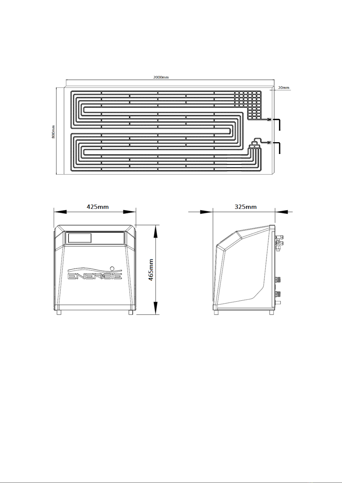
Thermodynamic Solar Panel
Weight
Kg
8
(2x) 8
Size of the packaging (a x l x p)
-
2000 x 800 x 20
(2x) 2000 x 800 x 20
Refrigerant fluid connections (in | Out)
Pol.
1/4” | 3/8”
Tank Requirements
Maximum Tank Capacity
lts
300
Minimum Coil Area (when using back-
up connections)
m2 1,5
7. ASSEMBLY SCHEME
1
Thermodynamic solar panel
4
Suction line
2
SolarBox
5
Liquid line
3
Cylinder
6
Temperature probe
TECHNICAL MANUAL SOLAR BOX
8
8. ASSEMBLY SCHEME
8.1 Thermodynamic solar panel
8.2 Solar Box
9. PLACING EQUIPMENT
9.1 Thermodynamic solar panel
The location and the angle at which the panels are installed must be taken into
account. In order to take full advantage of the solar radiation in question, the
panels should be set at an angle of between 10° - 85° to the ground, and
preferably pointing south.
The panel comes with six M8 holes on the side flaps. The distance between the
holes at the location where the panel is to be placed should coincide with the
holes in the panel.

TECHNICAL MANUAL SOLAR BOX
9
The panel has 3 small profiles (side A) and 3 large profiles (side B) which shall
be fixed according stipulations in the diagram, giving the panel the desired
level of inclination.
The profile shall be fixed to a base (e.g. a roof) via the provided plastic wall plugs and the self-
tapping M6 screws. The M6 screws and the respective nuts and washers shall make the panel
fixing to the profiles.
Panel profile fixing process
1
Aluminum profile
2 Plastic wall plug
3
Self-tapping screw (M6x40)
4
Washer M6
5
Screw (M6x20)
6
Nut M6
7
Panel

TECHNICAL MANUAL SOLAR BOX
10
The solar panel shall always be installed with the connections facing downwards.
The right or left panel shall always be installed horizontally, not vertically.
A – Panel input | B – Panel Output
WARNING
The panel should always be installed downwards, with the connections facing
down and shall be installed horizontally
9.2 Fixing Solar Box on horizontal surface
9.3 Refrigerant connections – Thermodynamic panel (1 panel)
WARNING
The refrigerant connections should be dealt with by a qualified technician holder
of a professional skills certificate for the purpose.
INFO
The thermodynamic unit holds a pre-load of R134a fluid.
WARNING
The refrigerant connections should be thermally insulated in order to avoid
burns and to ensure the maximum performance of the equipment.
•A lay the structure on a level and stable surface,
checking the four anti-vibratory brackets have
been duly mounted;
•Remove the half holes from the rear of the
structure by twisting the metal part you wish to
remove;
•Secure the connections on the rear of the structure.

TECHNICAL MANUAL SOLAR BOX
11
Pipe diameter
Number of panels
Vapour
(Suction line)
Liquid
(Line to the panel)
1 3/8’’ (9,52mm) 1/4’’ (6,35mm)
2 1/2’’ (12,7mm) 3/8’’ (9,52mm)
a) Prepare the copper pipe, removing the protective caps from the ends;
b) Place the end of the pipe face-down, cut the pipe at the desired distance and clean any
frayed edges;
c) Remove the nuts from the connections and place them on the side of the pipe;
d) Flange the pipe with an appropriate tool, forming a cone, ensuring there are no frayed
edges or imperfections and the lengths of the walls are the same;
e) Tighten the nut a few turns with your hand, and then execute the final tightening by
twisting in accordance with the values illustrated in the table.
INFO
TECHNICAL MANUAL SOLAR BOX
12
Pipe Diameter (inch) Applied Torque (Nm) Wrench nº
1/4” 14 a 16 19
3/8” 33 a 42 21
9.4 Refrigerant connections – Thermodynamic panel (2 panels)
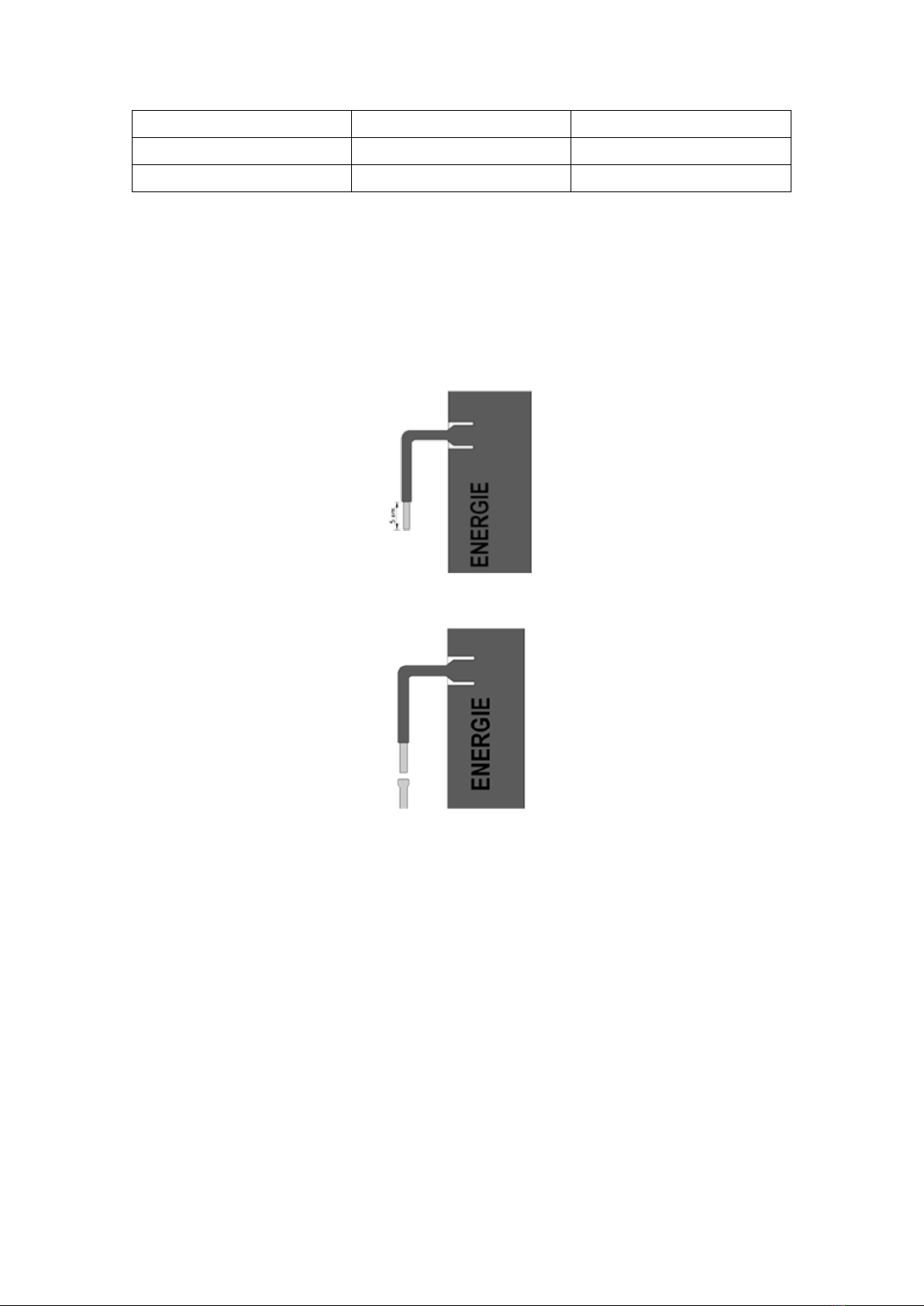
Remove the protecting caps from the ends of the copper piping.
Place the end of the tube so that it is pointing downwards, cutting the pipe at the intended point,
making sure to clean off any burrs (e.g. with a reamer).
Next, remove the covers from the panel connections, and with the aid of a cutting tool such as
a penknife, remove 5 cm of the thermo-retractable sleeve.
A 3/8” piping expansion area must be made, with the aid of an appropriate tool, for proper
connection to the panel.
Line up the liquid and suction tubes, but before commencing the welding operation, make sure
to protect the thermo-retractable sleeve by using a damp cloth.
The type of solder recommended for welding the pipes is type oxyacetylene
(Oxygen/Acetylene). Other types of gases can also be used, such as propane for example.
After carrying out the panel connection welding operations, but before installing the
Thermodynamic Block, make sure the apparatus has been cleaned with nitrogen.
For installations with two or more panels, it is essential that the fluid is homogeneously
distributed (panel entry). The equipment already comes installed with a liquid distributor so that
this process can be accurately put into effect.
Removal of thermo-retractable
sleeve
Piping expansion (3/8”)

TECHNICAL MANUAL SOLAR BOX
13
This distributor is placed between the two panels. The panel connecting pipes (1/4”) must be
exactly the same length, their extremities connecting directly to the panels.
Liquid distributor (liquid line)
The same level of pipe symmetry exactness is not required in relation to the suction
connections (Panel exit). This must be done by “denting” or with a “T” connection (in
accordance with the following image), being properly insulated.
Suction line
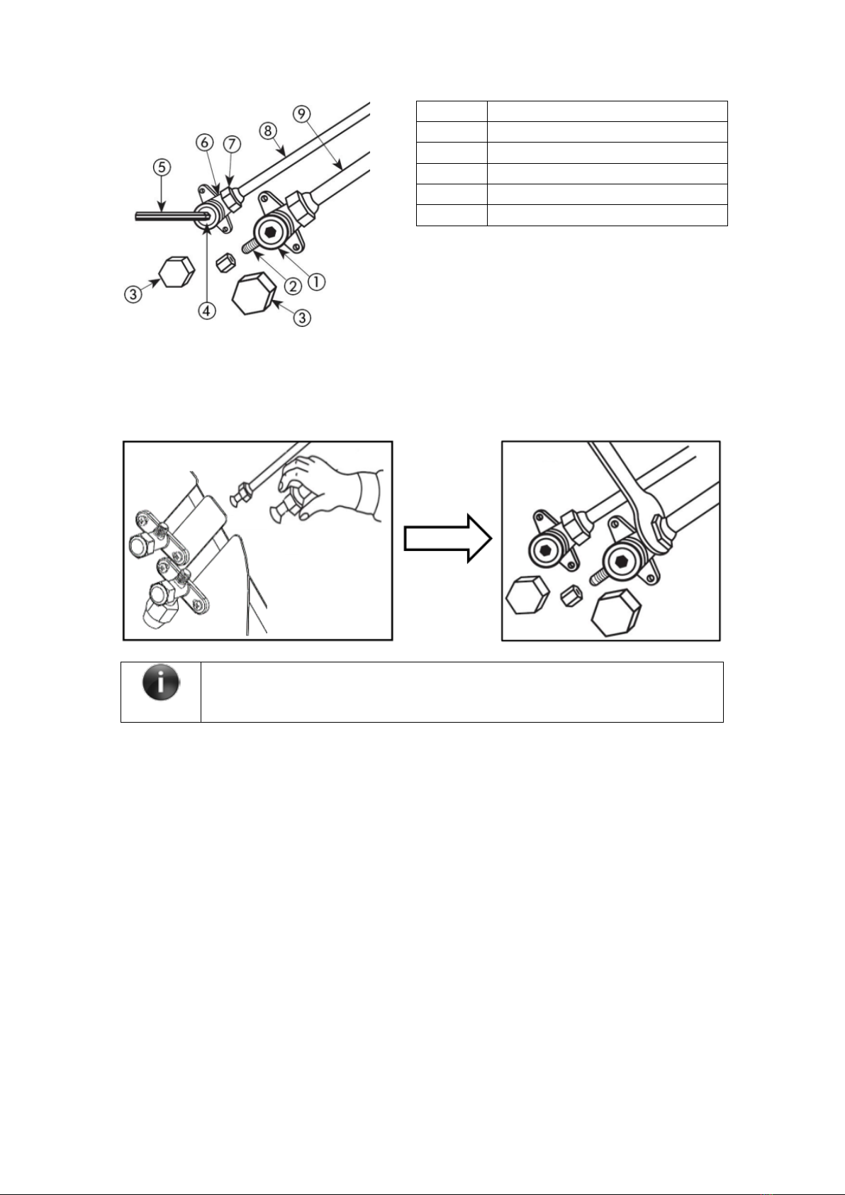
9.5 Refrigerant connections – Solar Box
Some of the steps involved here are exactly the same as the procedures followed to connect the
panel.
•Cut the pipe at the desired point with the end facing down. Clean any frayed edges.
•Flange the pipe not forgetting to place the nut on the side of the pipe.
Legenda:
1
3-way valve
2
Pressure tap
3
Valve sleeve
Liquid distributor
TECHNICAL MANUAL SOLAR BOX
14
•Tighten the nut a few turns with your hand and then use an appropriate spanner to fully
tighten the same as described above
INFO
ALL THE PIPES SHOULD BE INSULATED!
10. NITROGEN LOADING
Once the connections have been concluded the user needs to check there are
no leaks. To this end, a load of nitrogen at a pressure of 10 bar should be
injected via the pressure tap (3-way valve).
Cover all the connections in soap foam and check if the pressure on the gauges is constant.
11.VACUUM
a) Always use connections, vacuum pump and gauges duly adapted for R134a fluid;
b) Only use a vacuum pump to remove the air and moisture existing in the pipe;
c) Never use the system refrigerant to purge the pipes;
d) Keep the stop valves completely closed;
e) Connect the hose from the vacuum pump to the 3-way valve;
f) Create a vacuum with the pump connected to the pressure tap to the 3-way valve (for
4
Valve needle
5
Hexagonal spanner
6
2-way valve
7
Conical nut
8
Liquid line
9
Gas line

TECHNICAL MANUAL SOLAR BOX
15
30 minutes);
g) Once the vacuum process has been concluded (30 minutes), turn off the pump and the
gauge should always display the same value;
h) Turn off the gauge taps;
i) After this vacuum process has been concluded, the two valves should be opened to
enable the coolant to circulate throughout the system.
INFO
After creating the vacuum, do not remove the hoses until the system has been
fully pressurized by the coolant.
After creating the vacuum, do not remove the hoses until the system has been
fully pressurized by the coolant.
12.WATER QUALITY
INFO
The water you use may contain impurities and/or substances damaging to the system and
even harmful to your health. Make sure you use water with quality fitting for home
consumption. The following table indicates some parameters according to which water must
be subjected to chemical treatment.
Hardness (ºdH)
pH
Treatment
3,0 to 20,0
6,5 to 8,5
NO
3,0 to 20,0
<6,5 or >8,5
YES
<3,0 or >20,0
YES
13.HYDRAULIC CONNECTIONS
To assemble the couplings of the hydraulic circuit you must:
a) Connect the water inlet and outlet of the equipment with tubing or joints capable of
supporting a combined temperature/pressure of a constant 75°C / 7 bar. For such we
recommend the use of tubing which is resistant to high temperatures and pressures, such as
PEX, PPR, among others.
b) A safety valve needs to be installed at the cold water line of the equipment. The safety
device should comply with standard EN 1487:2002, discharge pressure of 7 bar (0.7 MPa).
c) In addition to this device other components need to be installed to guarantee the
interruption of the hydraulic load, in the following order:
• One way valve
• Pressure reducing valve (3 bar)
• Safety discharge group
• Expansion vessel
The safety discharge group should be connected by tubing with a diameter which is never less

TECHNICAL MANUAL SOLAR BOX
16
than the cold water inflow connection.
The part of the exhaust should be connected to an interceptor, or, in the event this is inviable,
raised at least 20mm above the floor to allow for visual inspection.
All the above recommendations are to guarantee the safety of people, animals and others. Solar
Box may be installed in tanks with two or more connections.
The diagrams below illustrate types of connection to a tank:
13.1 Vented installation
13.2 Tank with two connections

TECHNICAL MANUAL SOLAR BOX
17
13.3 Tank with more than two connections
13.4 Tank with backup connections

TECHNICAL MANUAL SOLAR BOX
18
Legend
1
Open/closed Valve
7
Drain
2
Non return Valve
A
Mains Water
3
Pressure Reducing Valve
B
Hot Water Outlet
4
Security Group
C
Solar Box
5
Expansion Vessel
D
Thermodynamic Panel
6
Filter
S1
Temperature Probe
14.FILTER
The filter allows block any impurities present in the hydraulic circuits. Residue left in the heater
pipes will damage the heat exchangers and cause the Solar Box to malfunction. It is
recommended install the filter in the heater return line. It is indispensable in order to prevent
serious damage to the heat exchanger.
15.AIR PURGE
After doing the correct installation of the system, the installer must purge all the hydraulic circuit
before turning on the Solar Box.
a) Ensure that the valve 1a is closed;
WARNING
The equipment is supplied with a “y” filter placed
on the Solar
Box hydraulic return line, at the
entrance of the heat exchanger.

TECHNICAL MANUAL SOLAR BOX
19
b) Close de valve 1b;
c) Open the purge valve inside the Solar Box;
d) Open the discharge valve (drain) 7;
e) Open valve 1a;
f) Close the bleed valve inside the Solar Box (only when there is water with no bubbles
leaving the valve);
g) Close the valve 1c (only when there is water with no bubbles leaving the valve);
h) Open the valve 1b;
i) Turn-on the Solar Box;
16.ELECTRICAL CONNECTIONS
Check the following conditions before implementing the electrical connections:
a) The thermodynamic equipment should only be powered electrically after the tank has
been filled.
b) The thermodynamic equipment should be connected to monophasic voltage (230 VAC /
50 or 60Hz).
c) Connections should always comply with the installation regulations in force in the
country in which the thermodynamic equipment is installed.
d) The equipment must be connected to an electrical grounded socket.
NOTE: The Solar Box equipment have a relay to allow the connection of a backup electric
resistance with maximum power of 3kW.

TECHNICAL MANUAL SOLAR BOX
20
17.ELECTRONIC CONTROLLER
CODE CONNECTO
RS
DEVICE CHARACTERISTICS
INPUTS
S1
S1
Water Probe
Sensor NTC10K@25°C, functioning
temperature 0÷120°C, Reading Range
0÷99°C
LP LP Low Pressure
Contact
Contact Open/Closed
HP
11
High Pressure
Contact
Contact Open/Closed
12
OUTPUTS
3
N
Pump Power 230 Vac Max 3A
230Vac
4
FON
5
N
Electrical
Heater
Power 230 Vac Max 3A
230Vac
6
FOFF
7
FON
8
COM
Compressor
Free contact Max 8A
230Vac
9
N.C.
10
N.O.
LINE
1
F
Input Line 230 Vac +/-10% 50 Hz;
Protection Fuse T3,15 A
2
N
Absorbed Power:
2VA
Applied rules:
EN 60730-1 50081-1 EN 60730-1 A1 50081-2
1 – ON/OFF
The ON/OFF of the controller is performed by the extended pressure of the button K4
•The OFF state is signaled by OFF of the display and all leds;
•
The ON state is signaled by the led L9 ON.
2 – START/STOP operations in ON state
•Fill the tank with water and expel any existing air, opening a hot water tap;
•The START/STOP of the operations is through the extended pressure of the button K3
(CP);
•
The STOP is signaled by the led L9 blinking.
Table of contents
Other Energie Solar Panel manuals


