Beretta SCF-V25 User manual

SOLAR
COLLECTOR
SCF-V25
INSTALLATION MANUAL
SOLAR

This booklet code 20051421 - Rev. 5 (01/14) comprises 12 pages.
2
Conformity
CONFORMITY
Solar collectors conform to EN 12975 standard and to Solar Keymark certification standard.
b This product must only be used for the purpose for which it is designed and made, as specified by B. B
declines all responsibility, contractual or other, for damage to property or injury to persons or animals caused by
improper installation, adjustment, maintenance or use.
Range
RANGE
MODEL CODE
SCF-V25 20050314
SCF-V25 (Pack of 2) 20050316
SCF-V25 (Pack of 5) 20050317
Contents
CONTENTS
The following symbols are used in this manual:
b
CAUTION! =
Identifies actions that require cau-
tion and adequate preparation.
a
STOP! =
Identifies actions that you MUST NOT
do.
This booklet code
- Rev.
comprises
pages.
System layout .................................. 3
Identification................................... 3
Technical data ................................. 4
Connections ................................... 5
Water circuit ................................... 6
Unpacking the product .......................... 7
Handling...................................... 7
Installation .................................... 8
Filling the circuit ................................ 9
Checks ...................................... 10
Maintenance.................................. 10

3
System layout
SYSTEM LAYOUT
100
1265
1240
2078
83
Collector
probe socket
Collector
outlet
Collector
return
Direction of flow of
heat transfer liquid
Glass 4 mm
Connector Ø 22 mm
Connection
ring nut, 1"
Ventilation holes
Identication
IDENTIFICATION
Data plate
Serial number plate
Code
Y
ear of production
Serial Number
Description Made in Italy
by Riello S.p.A.
Flat plate
solar collector
Dimensions
Gross area
Aperture area
Absorber area
Empty weight
Maximum operating pressure
Stagnation temperature
Liquid content
Max glycol concentration
Heat transfer fluid:
water+propylene glycol
FABBRICATO IN ITALIA
DESCRIZIONE : CP25VVA
S/N :
COLLETTORE SOLARE PIANO
DIMENSIONI: 2076X1238X100 mm
SUPERFICIE LORDA: 2,57 m2
TEMPERATURA DI STAGNAZIONE: 201,7 °C
SUPERFICIE DI APERTURA: 2,30 m2
CONTENUTO LIQUIDO: 1,6 l
SUPERFICIE ASSORBITORE: 2,15 m2
PESO A VUOTO: 45 kg LIQUIDO TERMOVETTORE:
ACQUA+GLICOLE PROPILENICO
MAX CONCENTRAZIONE GLICOLE: 50%
MAX PRESSIONE ESERCIZIO: 10 bar
da Riello S.p.A.
EN 12975
Certif. 011-7S1983 F
12000025
Anno di produzione
CODICE : 20048333
20048313_E1
SERIALE PROGRESSIVO
Cod.
Mod.
Serial number
b If these plates or any other means of clearly identifying the product are defaced, removed or lost, proper installation
and servicing may be rendered difficult.

4
Technical data
TECHNICAL DATA
DESCRIPTION
Total area 2,57 m2
Exposed area 2,30 m2
Effective absorption area 2,15 m2
Connections (M) - (F) 1"
Empty weight 45 kg
Liquid content 1,6 l
Recommended flow rate for each line per m2of collector 30 l/(h x m2)
Minimum flow rate for each line per m2of collector 12 l/(h x m2)
Maximum flow rate for each line per m2of collector 60 l/(h x m2)
Glass thickness 4 mm
Absorption (α)~ 95 %
Emissions (ε)~ 4 %
Maximum permitted pressure 10 bar
Stagnation temperature 201,7 °C
Maximum number of collectors in a line 6 n°
Efficiency curve
1
0,8
0,6
0,4
0,2
00 0,02 0,04 0,06 0,08 0,1
0,12
Tm[m
2
K/W]
*
Optical efficien-
cy of absorber
(ηο)
Thermal dispersion factor of
absorber
a1 W/(m2K) a2 W/(m2K2)
0,809 3,72 0,011
Tested according to EN 12975, referred to a 33.3% wa-
ter-glycol mix, irradiation G = 800 W/m2.
Tm = (Coll._inlet _temp.+Coll._outlet_temp.)/2
T*m
= (Tm - ambient_temp)/G
WIND AND SNOW LOADS ON COLLECTORS
Installation
height above
ground
Wind speed
Mass in kg to secure collector
against lifting by wind
Load on roof from wind, snow, and
collector weight
At angle of
45°
At angle of
20°
At angle of
45°
At angle of
20°
0 - 8 m 100 km/h 80 kg 40 kg 320 kg 345 kg
8 - 20 m 130 km/h 180 kg 90 kg 470 kg 430 kg
20 - 100 m 150 km/h 280 kg 150 kg 624 kg 525 kg
Maximum permitted load from wind and snow (including combined loads) on surface of collector: 1500 Pa.

5
Connections
CONNECTIONS
half union
ring nut
seal ring
male union
sensor pocket
seal ring
toward the
heat transfer
circuit
When tightening a fitting,
HOLD THE OPPOSITE
FITTING STEADY WITH
A SECOND TOOL
to avoid damage
seal ring
from the
heat transfer circuit
The collectors in a line are connected so that the heat transfer fluid goes through them in series. The connection with the
heat transfer circuit that goes toward the heat exchanger must be the one near the sensor pocket of the last collector of
the line (see the picture above). It is also possible to connect more then one line of solar collectors both in series (max
6 collectors in series) or in parallel. Anyway the circuit must be hydraulically balanced (see the following schemes as an
example).
Two lines in series Two lines in parallel
T T
Diameter of connection pipes for a specic ow rate of 30 lt/m2h
Total surface area (m2) 2 - 4 6 - 12 14 - 20
Diameter of copper pipe
(mm) 10 - 12 14 18
Diameter of steel pipe (inch) 3/8" - 1/2" 1/2" 3/4"

6
Water circuit
WATER CIRCUIT
1
Solar collector
2
Storage cylinder
3
Collector probe
4
Disconnect valves
5
Non-return valve
6
Temperature gauge
7
Vent valve
8
Relief valve
9
Pressure gauge
10
Drain
11
Expansion vessel
12
Pump
13
Flow regulator
14
Flow meter
15
Vent cock
16
Manual bleed valve (acces-
sory)
17
Storage cylinder bottom
temperature sensor
18
Storage cylinder top tem-
perature sensor
19
Heat transfer fluid recovery
M
Collector outlet
R
Collector return
°C
M
4
4
4
9
8
11
10
13
14
6
12
7
5
19
3
11
RM
17
18
2
15
16
Water control system
Solar
Regulator
b If copper pipes are used, joints must be hot brazed.
b We recommend the use of stainless steel pipes spe-
cially made for solar collectors for the outlet, return
and probe pipes. The probe cable should be of the
shielded type.
b Do not use plastic or multistrate pipes. Operating
temperature can exceed 180°C.
b Pipe lagging must be able to resist high temperatures
(180°C).
Pressure drop in solar collectors (*)
140
120
100
80
60
40
20
0
0 100 200 300 400 500 600 700 800 900
1000
Pressure drop (mbar)
Flow rate (l/h)
(*) With antifreeze-water mix of 33,3% / 66,7% and heat transfer medium temperature = 20°C.

7
Unpacking the product
UNPACKING THE PRODUCT
The solar collectors are packed in various ways depending
on the number of units supplied:
A
Packages of 1 or 2 collectors
B
Packages of 5 collectors
Pallet contents:
- collector
- document envelopes containing instruction manuals,
test certificate and bar code label.
b The instruction manual is an integral part of the solar
connector. Once located, read it thoroughly and keep
it safe.
b
STORE IN A DRY PLACE AND DO NOT EXPOSE TO DI-
RECT SUNLIGHT UNTIL THE TIME OF INSTALLATION!
The packaging is not designed to protect the prod-
uct against rain or humidity. It can also degrade if ex-
posed to direct sunlight. Failure to comply with these
precautions could lead to irreparable damage to the
product.
A B
Handling
HANDLING
Once you have removed the outer packaging, proceed as
follows to unpack and handle the solar collector:
- Remove the PVC wrapping to free the solar collector
from the pallet.
- Tilt the solar collector slightly and grip it at the four
points shown (A) to lift it.
- Use a hoist or other suitable lifting equipment to hoist
the solar collector on to the roof.
b Wear suitable personal protective equipment and use
suitable safety devices.
a Do not dispose of packaging material into the envi-
ronment, or leave it within the reach of children, since
it can become a potential hazard. Dispose of packag-
ing material in compliance with applicable legislation.
a Do not lift the solar collector by its water fittings.
A
A
A
A

8
Installation
INSTALLATION
GENERAL INSTRUCTIONS
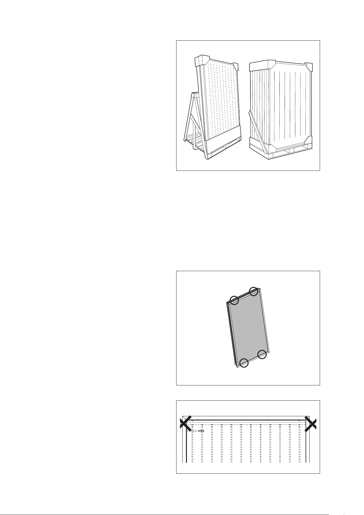
Assembly
The system must be installed by specialist personnel. Use
only the assembly material supplied with the solar collector.
The supporting framework and all masonry or brickwork fixing
points must be checked by a person expert in static loading,
and must be suitable for the nature of the installation site.
Static load
The solar collector must only be installed on roofs or frames
that are strong enough to support its weight. The strength of
the roof or frame must be verified on site by a person expert in
static loading before the solar collector is installed. During this
process, it is important to verify the suitability of the supporting
frame to hold the screw fasteners that fix the solar collector
in place. An expert in static loading must verify that the entire
frame complies with relevant standards, especially in areas
liable to snow and areas exposed to high winds. Conditions
(gusts of wind, formation of wind vortices, etc.) at the point
where the solar collector is to be installed must be carefully
considered since these can increase the loads on the sup-
porting structure.
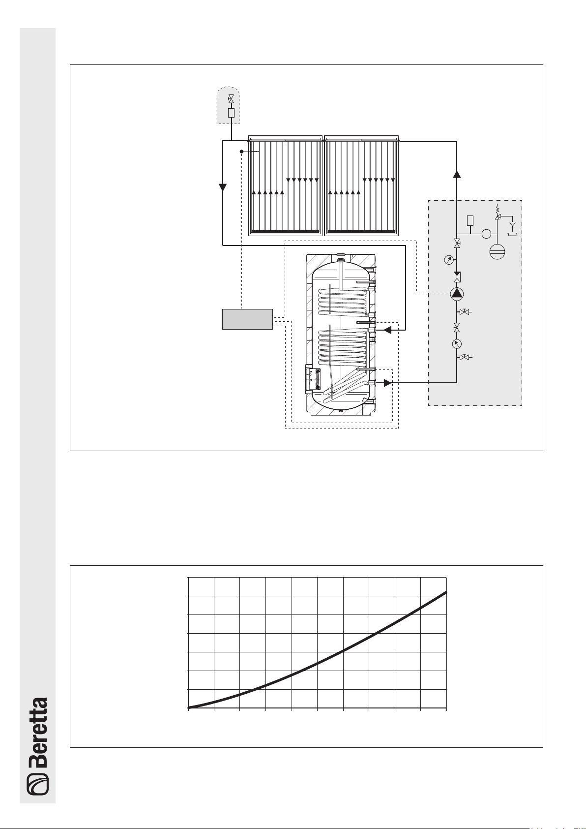
Lightning protection
The metal piping of the solar heating circuit must be connect-
ed to the main potential compensation bar by a (yellow-green)
copper wire (H07 V-U or R) of at least 16 mm
2
. If a lightning
conductor system is already installed, the solar collectors may
be connected to the existing system. Alternatively, the solar
collector piping may be connected to ground via a ground
wire sunk into the earth. Ground wires must be sunk outside
the house. The ground wire must be connected to the potential
compensation bar through a wire of the same diameter.
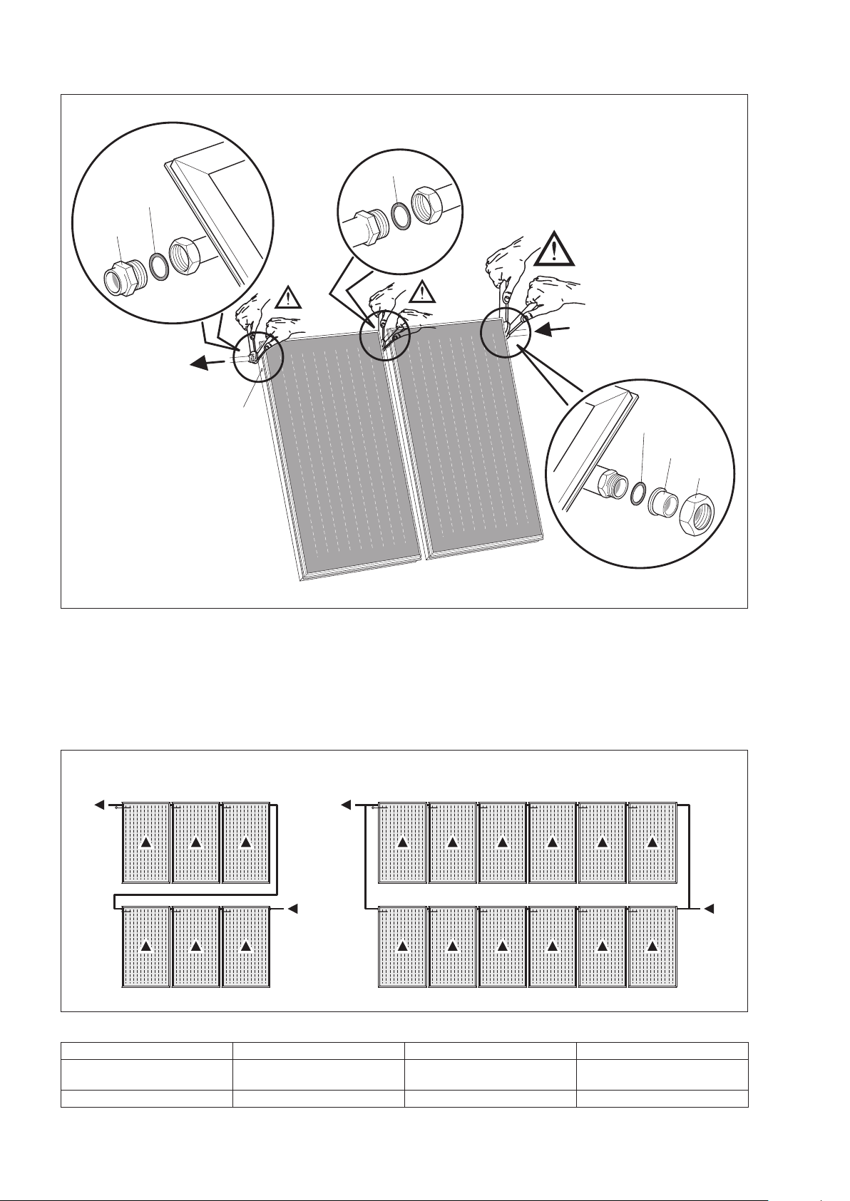
Water connections
When connecting solar collectors in a line, fit seal rings at both
ends of the connection fittings, taking care to ensure that they
are correctly positioned in their seats. Make all the necessary
connections, then check that all the ring nuts are properly tight-
ened. If the pipes used to connect the ends of the solar col-
lector line to the rest of the system are not sufficiently flexible
to absorb the stress imparted by thermal expansion, fit com-
pensating devices at both ends of the line (U-type expansion
joints, sections of flexible hose or dedicated expansion joints).
Up to 6 collectors may be connected in a line, but only if the
above provisions are made.
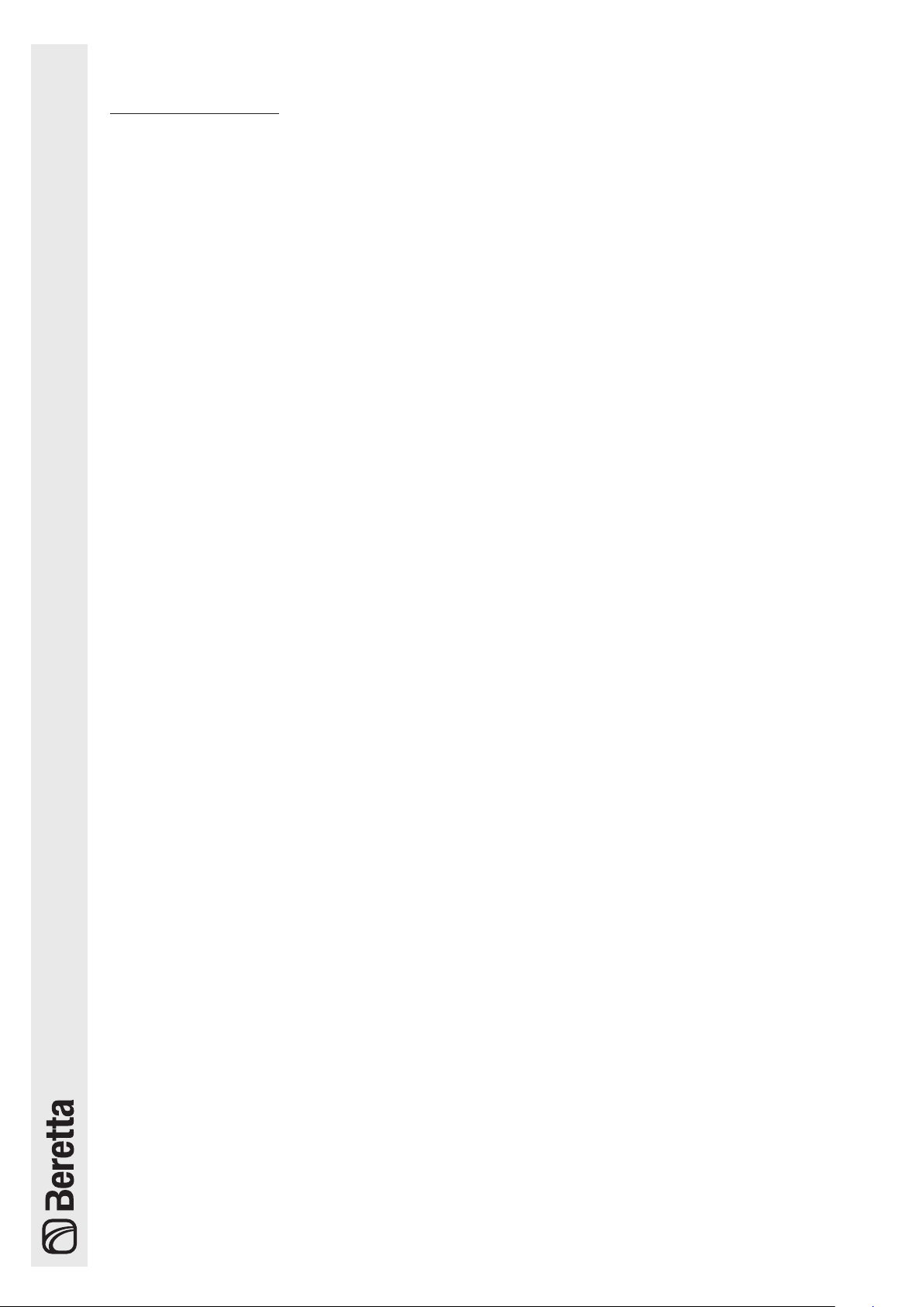
When tightening a fitting with a
pipe wrench or spanner, always hold the opposite fitting
steady with a second tool to avoid damaging the absorber.
b
All pipes in the water circuit must be insulated in con-
formity to relevant standards. Lagging and insulation
must be protected against damage by the weather and
birds and animals.
Angle of collectors / General
Solar collectors are designed to be installed at angles of be-
tween 15° (minimum) and 75° (maximum). Make sure that the
bleed and vent valves of the collectors remain open while the
collectors are being installed. Take care to protect all fittings,
connections, bleed and vent valves against dirt and dust etc.
In installations which serve primarily to produce domestic hot
water in the summer, install the collectors facing from east to
west at an angle of between 20 and 60°. The ideal orientation
is southwards, at an angle equal to the latitude of the location
minus 10°. If the system sustains the greatest thermal load in
the winter (as in systems that combine domestic hot water pro-
duction with central heating), install the collectors facing south
(or south-east or south-west) at an angle greater than 35°. The
ideal orientation is southwards, at an angle equal to the lati-
tude of the location plus 10°.
b
Work near uncovered and live electrical wires, with
which it is possible to come into contact, is only permit-
ted under the following conditions: wires must be free
from voltage for the entire duration of the work; parts
remaining live must be covered or accidental contact
prevented; the following minimum safety distances must
be respected: 1m (for voltages of up to 1000 Volts), 3m
(for voltages from 1000 to 11000 Volts), 4m (for voltages
from 11000 to 22000 Volts), 5m (for voltages from 22000
to 38000 Volts), >5m (if the voltage is not known). Con-
tact with open, live electrical wires may lead to electro-
cution and may even be fatal.
b
Always wear safety goggles when drilling. Always wear
safety shoes, cut-proof protective gloves and a safety
helmet when performing installation work.
b
Before beginning installation work on roofs, install the
necessary fall prevention and fall arrest devices and
ensure that all applicable safety standards are applied.
Use only tools and materials that conform to the safety
standards that are applicable in the place of work.
b
Only wear overalls that have a safety harness (with a
suitable safety or fall-arrest belt, ropes or slings, fall
dampers or dissipaters). In the absence of adequate fall
prevention and security devices, failure to use a proper
safety harness may lead to falls from great heights with
serious or even fatal consequences.
b
The use of ladders leaned against walls can lead to se-
rious falls if the ladder slips, slides of falls. When using
ladders, always ensure that they are stable, and that
suitable ladder stops are present. If possible secure the
ladder with hooks. Make sure that there are no live elec-
trical wires near the ladder.
b
In recessed installations (surrounded by flashing), make
sure that water cannot flow over the glass panel of the
solar collector from cement, brickwork or masonry. For
this reason, it is essential to avoid installing the collector
under cement work, chimneys and other structures.
b
Do not use this kit for recessed installations (surrounded
by flashing) on slate roofs.
b
Use only soap and water to clean the glass panels of
the collectors. Rinse with clean water after cleaning. Use
soft cloths to clean the glass. Do not use abrasive mate-
rials or corrosive substances.

9
Filling the circuit
FILLING THE CIRCUIT
Perform the following steps before starting up the system.
1 - FLUSHING AND SEAL TESTING THE SYSTEM
If copper piping has been used and joints have been hot
brazed, flush out the system to remove any brazing resi-
dues. Seal test the system after you have flushed it out.
b Fill the solar collector with glycol/water mix immedi-
ately after flushing it out, because flushing water may
remain trapped in the circuit (with a consequent risk
of freezing).
2 - PREMIXING WATER + GLYCOL
Glycol anti-freeze is supplied separately in standard vol-
umes and must be premixed with water in a suitable con-
tainer before being used to fill the system. For example,
a mix of 40% glycol and 60% water provides anti-freeze
protection down to a temperature of -21°C.
b The propylene glycol supplied is specially formulat-
ed for solar collector applications and remains fully
efficient throughout the -32 to +180°C temperature
range. It is also non-toxic, biodegradable and bio-
compatible.
b Do NOT part fill the circuit with pure glycol then add
water later.
3 - FILLING
b
Only ll and bleed the solar circuit at ambient temper-
ature, with the collectors shielded from the sun’s rays.
1 Open the non-return valve (A)
2 Open the air vent at the highest point in the system (see
figure alongside) and keep it open throughout the filling
operation
3 Open the vent valve (7)
4 Pump the heat transfer fluid around the circuit with an
external filling pump until all air bubbles have been
eliminated. Close the manual bleed valve
5 Temporarily raise the pressure in the system to 4 bar
6 Start up the system for about 20 minutes
7 Bleed the circuit again from step 2 until all the air has
been removed
8 Set the circuit pressure according to the table on the
next page in order to ensure a minimum pressure of 1.5
bar at the height of the collector field
9 Close the non-return valve (A) and any open vent valves
to prevent the heat transfer fluid from evaporating.
b Make sure that you have bled all the air out of the sys-
tem, using the water control system vent too.
Heat transfer fluid filling pump (accessory). A manual
bleed valve is not required if this pump is used.
Anti-freeze Temperature Density
50% -32 °C 1.045 kg/dm3
40% -21 °C 1.037 kg/dm3
30% -13 °C 1.029 kg/dm3
M
A
R
M
7
°C
Manual
bleed valve
(accessory) Solar collector
Heat
transfer fluid
filling pump
Anti-freeze mix
Water control system
Heat e
xchanger
of solar

10
H
H Pressure at boiler
up to 15 m 3 bar
15 - 20 m 3,5 bar
20 - 25 m 4 bar
25 - 30 m 4,5 bar
General rule: p [bar] = 1.5 + H [m] / 10
Checks
On completion of the installation, perform the checks listed in the table below.
CHECKS
Collector circuit
Cold circuit pressure:____bar (see table
above)
Collector circuit seal test
Safety valve check
Anti-freeze checked to - ___ °C
pH of heat transfer fluid = ____
Collector circuit bled
Flow rate of 30 l/h per m2checked
Non-return valve functioning
Solar collectors
Visual check of collectors
Collectors cleaned if necessary
Visual check of collector fixing points
Visual check of roof impermeability
Visual check of insulation/lagging
Maintenance
Service the system and perform the checks listed in the tables below at least once every two years.
MAINTENANCE
Collector circuit
Cold circuit pressure:____bar (see table
above)
Collector circuit seal test
Safety valve check
Anti-freeze checked to - ___ °C
pH of heat transfer fluid = ____
Collector circuit bled
Flow rate of 30 l/h per m2checked
Non-return valve functioning
Solar collectors
Visual check of collectors
Collectors cleaned if necessary
Visual check of collector fixing points
Visual check of roof impermeability
Visual check of insulation/lagging
Checking the heat transfer liquid
Check the anti-freeze effect and the pH level of the heat transfer liquid every 2 years.
- Use an instrument like a refractometer or densimeter to check the anti-freeze effect (which must have a nominal pro-
tection value of approx. -30°C). If the protection threshold is higher than -26°C, replace the mix, or add anti-freeze
as required.
- Use litmus paper to check the pH (nominal value approx. 7.5). If the measured value is below 7, change the heat
transfer liquid.

11

20051421 - Rev. 5 (01/14)
Via Risorgimento, 13 - 23900 Lecco (LC) - Italy
Customer Service 199.13.31.31
www.berettaclima.it
The manufacturer strives to continuously improve all products. Appearance, dimensions, technical specications, standard equipment
and accessories are therefore liable to modication without notice.
This manual suits for next models
3
Table of contents
Other Beretta Solar Panel manuals
Popular Solar Panel manuals by other brands

Kyocera
Kyocera OFF-GRID MODULES datasheet

aiko
aiko AIKO-A MAH54Mw Series installation manual

Panasonic
Panasonic EverVolt EVPV K Series General installation manual

SOLUXTEC
SOLUXTEC PowerSlate Framed Mono Dark Blue Series user manual

Klein Tools
Klein Tools 29251 instruction manual

PHOTOWATT
PHOTOWATT PW72HT-C installation manual