En-Eco Enecom HF20-5-16 User manual
MANUAL ISSUED BY:
Headquarters
ENECOM s.r.l.
Via Odorico da Pordenone, 28
FLORENCE - Italy
Version:
Title Version Date
MODULES HF - Instruction Manual 2 10/2017

CONTENTS
Introduction 2
The manual 2
The HF photovoltaic module 3
Front surface 3
Back surface 4
Identification 5
Technical specifications 6
Instructions for use 8
Installation 9
General rules for installation 9
Orientation 9
Mounting 10
Electrical connections 11
Maintenance 15
Warranty 16
Contacts 16
2
INTRODUCTION
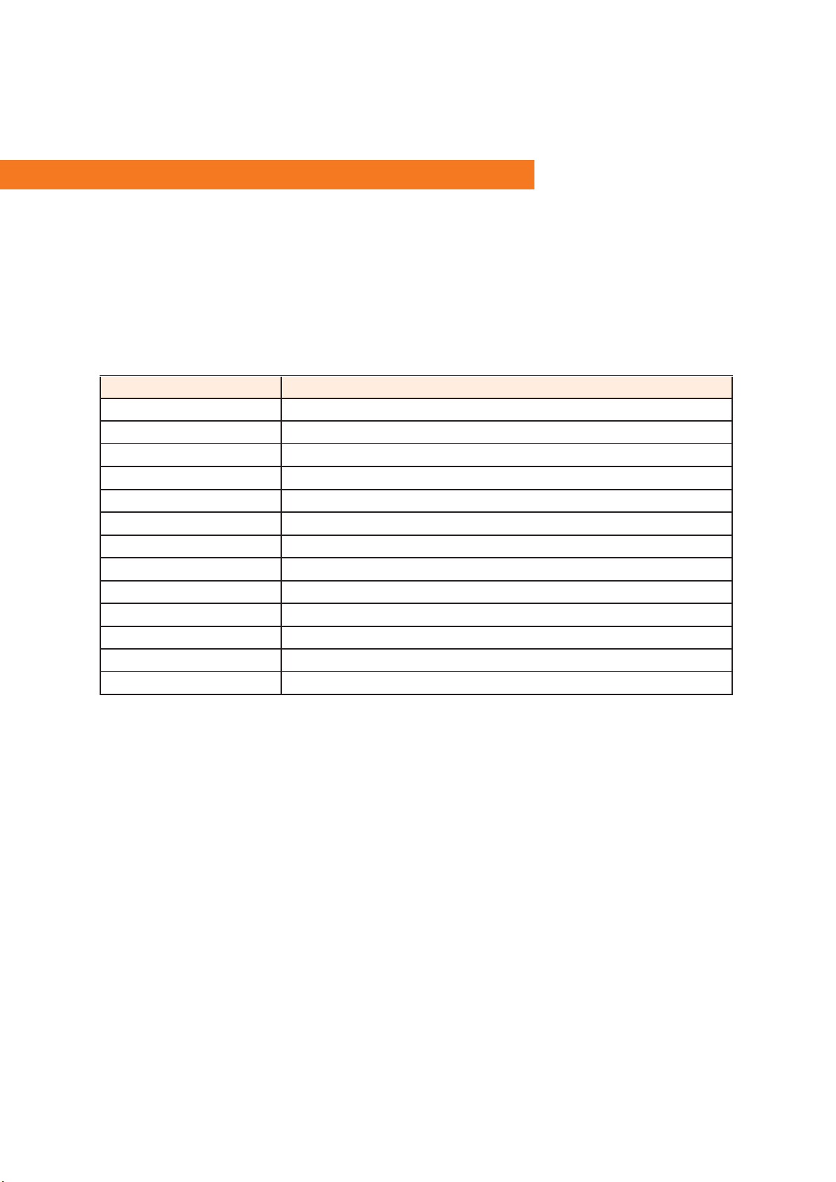
This manual provides an overview of Enecom HF photovoltaic modules and their use. It
covers the following Enecom modules:
Module Code Description
HF20-5-16 Flexible m-si module: 620 mm × 292 mm
HFp20-5-16 Pliable flexible m-Si module: 320 mm × 280 mm (closed)
HF40-5-16 Flexible m-Si module: 604 mm × 536 mm
HFp40-5-16 Pliable flexible m-Si module: 560 mm × 280 mm (closed)
HFs40-5-16 Flexible m-Si module: 1120 mm × 282 mm
HF65-6-16 Flexible m-Si module: 728 mm × 660 mm
HFs65-6-16 Flexible m-Si module: 1370 mm × 344 mm
HF80-5-16 Flexible m-Si module: 1104 mm × 536 mm
HF90-5-18 Flexible m-Si module: 1230 mm × 536 mm
HF135-6-16 Flexible m-Si module: 1350 mm × 660 mm
HFpy120-6-16 Flexible p-Si module: 1350 mm × 660 mm
HFsp 90-5-16 Flexible m-Si module: 970mm × 536 mm
HFsp120-5-21 Flexible m-Si module: 1250mm × 536 mm
This manual also applies to modules which have been custom designed to the
customer’s specifications.

3
THE HF PHOTOVOLTAIC MODULE
Introduction
A photovoltaic module is a device that converts solar energy into electrical energy, thanks to
the presence of silicon cells within which the physical phenomenon known as the
“photovoltaic effect” takes place. The greater is the number of silicon cells in the photovoltaic
module, the more electrical energy is produced.
The front surface of the photovoltaic module
The front surface of the module must be exposed to direct sunlight.
Connectors
Cables
Junction box
Cells
The junction box, at the request of the customer, can be placed on the back surface.

4
Back surface of the photovoltaic module
Bipolar cable
Connector
Junction box
Cells
In HFp modules the junction box is positioned on the back surface.
In HF and HFs modules the back surface of the module has no components; it provides only the
identification label bearing the serial number of the module and the electrical data plate
(unless the junction box has been positioned on the back surface, in which case the junction
box will also be present).
Serial number and
module data

5
Identification
Every Enecom module is identified by a label on the back surface with the following
information.
ENECOM s.r.l. gruppo EN-ECO S.p.A.
Via Emilia, 6 10099 San Mauro Torinese (TO) - ITALY 1. Panel type
2. Serial number of the
module,year and place
of production (SMT =
San Mauro Torinese, MM
=Montemurlo)
3. Date of production
4. Maximum power
5. Open circuit voltage
6. Short circuit voltage
7. Voltage at maximum
power
8. Current at maximum
power
9. Maximum system
voltage
10. Nominal power
measured at Standard
Test Conditions (STC)
Do not remove or tamper with the label.
MODULE TYPE:
1)
Serial Number
2)
Data produzione
3) gg/mm/aa
Maximum power (Pmax)
4)
Wp
Open circuit voltage (Vca)
5)
V
Short circuit current (Isc)
6)
A
Voltage at max power (Vmp)
7)
V
Current at max power (Imp)
8)
A
Maximum system voltage
9)
V
10) Nominal power misured at standard test condition (STC):
l = 1000 W/m² Tamb = 25°C AM = 1.5
6
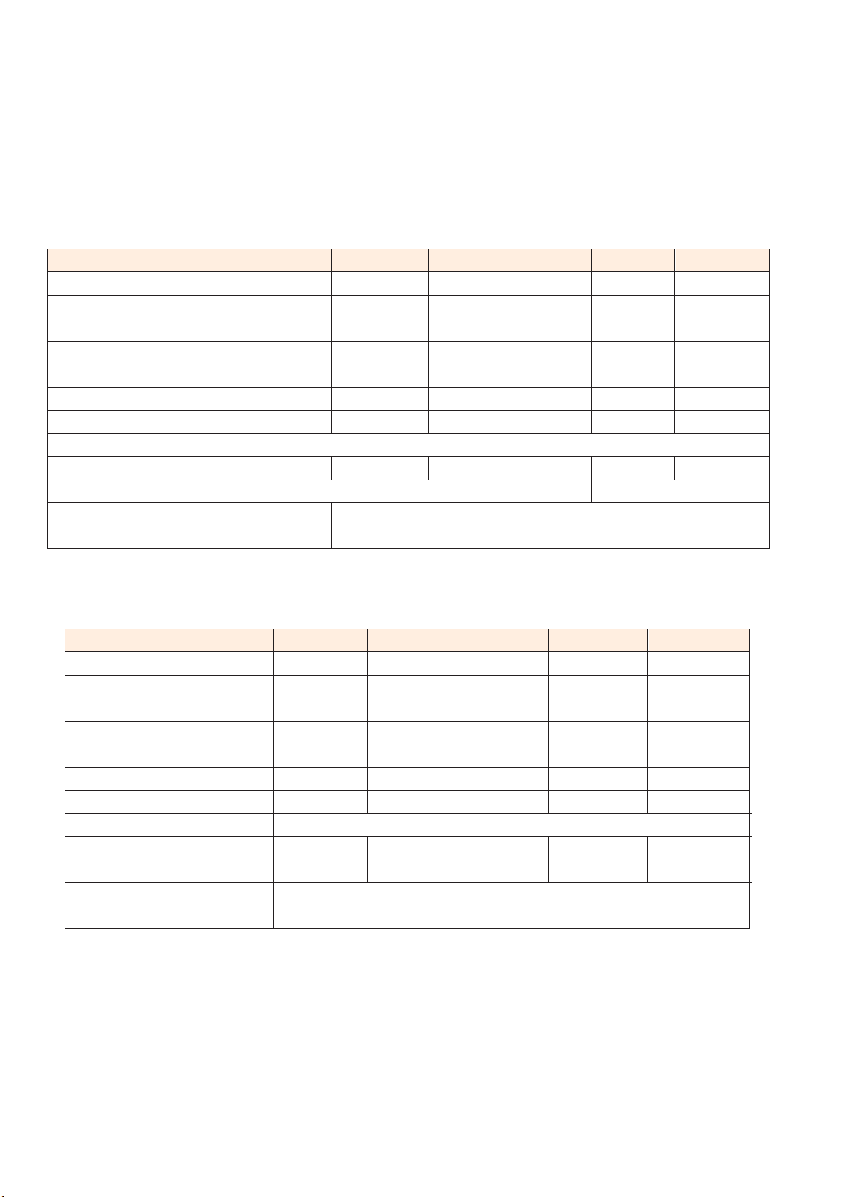
Technical specifications
Technical specifications of the HF line
HF20-5-16
HF40-6-16
HF80-5-16
HF90-5-18
HF65-6-16
HF 135-6-16
Max power Pmax(Wp) ± 3%
20
40
80
90
65
135
Open circuit voltage Voc (V)
19,63
19,63
19,63
22,42
20,2
20,2
Short circuit current Isc (A)
1,40
2,80
5,61
5,61
4,36
8,61
Voltage at Pmax Vmp (V)
16,23
16,23
16,23
18,54
16,4
16,4
Current at Pmax Imp (A)
1,33
2,65
5,31
5,15
4,07
8,14
Number of cells
32
32
32
36
32
32
Size (w x h) in mm
620 x 292
604 x 536
1104 x 536
1230 x 536
660x728
1351 x 660
Thickness in mm
1,8-2 mm
Weight (kg)
0,5
0,8
1,3
1,5
1,3
2,2
Cell efficiency
18,6%
18,6%
Output terminals
MC4 connectors
Maximum system voltage
600 V
Technical specifications of the HFs-HFsp-HFpy line
HFs40-5-16
HFs65-5-16
HFsp90-5-16
HFsp120-5-21
HFpy120-6-16
Maximum power Pmax(Wp)
40
65
90
120
120
Open circuit voltage Voc (V)
19,63
20,2
19,9
25,66
19,68
Short circuit current Isc (A)
2,80
4,36
6,01
6,01
8,56
Voltage at Pmax Vmp (V)
16,23
16,4
17,1
22,1
16,3
Current at Pmax Imp (A)
2,65
4,07
5,65
5,65
8,05
Number of cells
32
32
28
36
32
Size (w x h) in mm
1120 x 282
1370 x 344
977x536
1230x536
1350x660
Thickness in mm
1,8-2 mm
Weight (kg)
0,8
1,2
1,5
1,8
2,2
Cell efficiency
18,6%
18,6%
22,3 %
22,3%
17,8%
Output terminals
MC4 connectors
Maximum system voltage
600 V

7
Technical specifications of the HFp line
HFp20-5-16
HFp40-6-16
Maximum power Pmax(Wp) ± 3%
20
40
Open circuit voltage Voc (V)
19,63
19,63
Short circuit current Isc (A)
1,40
2,80
Voltage at Pmax Vmp (V)
16,23
16,23
Current at Pmax Imp (A)
1,33
2,65
Number of cells
32
32
Size (w x h) in mm
320 × 280 (closed)
560 x 280 (closed)
Thickness in mm
1,8-2 mm
Weight (kg)
0,6
0,9
Cell efficiency
18,6%
Output terminals
Cigarette lighter style socket / MC4 connectors
Maximum system voltage
600V
Technical specifications of the wired junction box
Junction Box Size
82 x 64 x 13 mm
Diode
one-two bypass diodes
IF
12 A
VDC
45V
Temperature range
-40 ÷ 80 °C
Protection class
IP67
Technical characteristics of the connectors
HF20-5-16
HFp20-5-16
HFp40-5-16
HF40-5-16
HFs40-5-16
HFs65-6-16
HF80-5-16
HF90-5-18
HF130-6-16
HF20-5-16
HFp20-5-16
HFp40-5-16
Connector type
Standard cigarette
lighter style socket
Standard MC4
Protection class
IP22
IP67

8
Warnings
Please read and follow these general instructions and warnings carefully; failure to comply with these
instructions will void the warranty.
•
Leave the photovoltaic module in the packaging until it is installed.
•
Check the physical integrity of the module before installation.
•
Contact with electrically active parts of the module can generate sparks and
electrical discharges at low voltage: please use caution.
•
The photovoltaic module produces electricity when the front part is exposed to
sunlight. Please use caution.
•
When modules are connected “in series” the voltage is cumulative, whereas
when connected “in parallel” the current is cumulative. For this reason, a system
with multiple modules connected to each other can produce high voltages and
currents that can be a source of danger and can cause serious injury or death.
Use caution.
•
The photovoltaic module must be handled with care, without excessive
bending. The minimum suggested curvature radius is 1meter, if lesser curvature
radius is needed contact the technical support that will provide you a response
about the feasibility of the installation.
•
Do not move the panel taking it by the connection cables.
•
Do not put localized pressure on the cells.
•
Avoid prolonged partial shade on the module.
•
Do not use the photovoltaic module for purposes other than those for which it
was designed and built.
•
Do not place the module near sources of heat.
•
Do not disassemble or modify the module components (junction box, cables
and connectors).
•
Do not pierce the module, even in areas that are far away from the cells.
•
Do not use paint on the front or the back.
•
Do not walk on the module.
•
Do not concentrate sunlight or artificial light sources on the module.
•
Do not short-circuit the module connectors (do not connect them together).
RISKS FROM MECHANICAL DAMAGE

9
INSTALLATION
General rules for installation
For correct installation of the photovoltaic module, it is necessary to follow these guidelines.
•
A photovoltaic module generates electricity when exposed to sunlight; it is
advisable to fully cover the surface of the front side with a dark opaque material
to block sunlight during installation or removal.
•
During operation, the module tends to heat up (because of both the effect of
solar radiation and the physical phenomenon of photovoltaic action). To improve
the performance of the module, it is therefore important to facilitate the dispersal
of heat. Fastening the module to thermally insulating materials is not
recommended because it would impede the dispersal of heat.
•
If the support chosen for the installation site is metallic (and therefore conducts
electricity), when installing, be careful to avoid any contact between the metallic
material and the electrical terminals of the module.
•
During installation, be careful to comply with safety regulations and general
instructions.
•
Installation should only be undertaken in dry conditions, keeping the photovoltaic
module and all tools dry and adequately insulated.
•
Do not install the photovoltaic module in the vicinity of flammable gases or vapors.
•
Choose an installation location which is exposed to direct sunlight as much as
possible; avoid shaded areas.
•
In the event that the cables need to be extended (e.g., to connect the module to
a charge regulator), the electrical conductor section of the extension cord should
be large enough to avoid excessive voltage drops with relative loss of power.
Orientation
In general the best energy performance of the module can be approximately obtained by
installing the device:
•
facing south;
•
at an inclination equal to the latitude from the horizontal.
Installing the module at non-optimal inclination and orientation lead to reduce the module’s
power output.
12
Mounting
The photovoltaic module can be mounted in the following ways:
•
mechanically with eyelets
•
bonding it using double sided adhesive
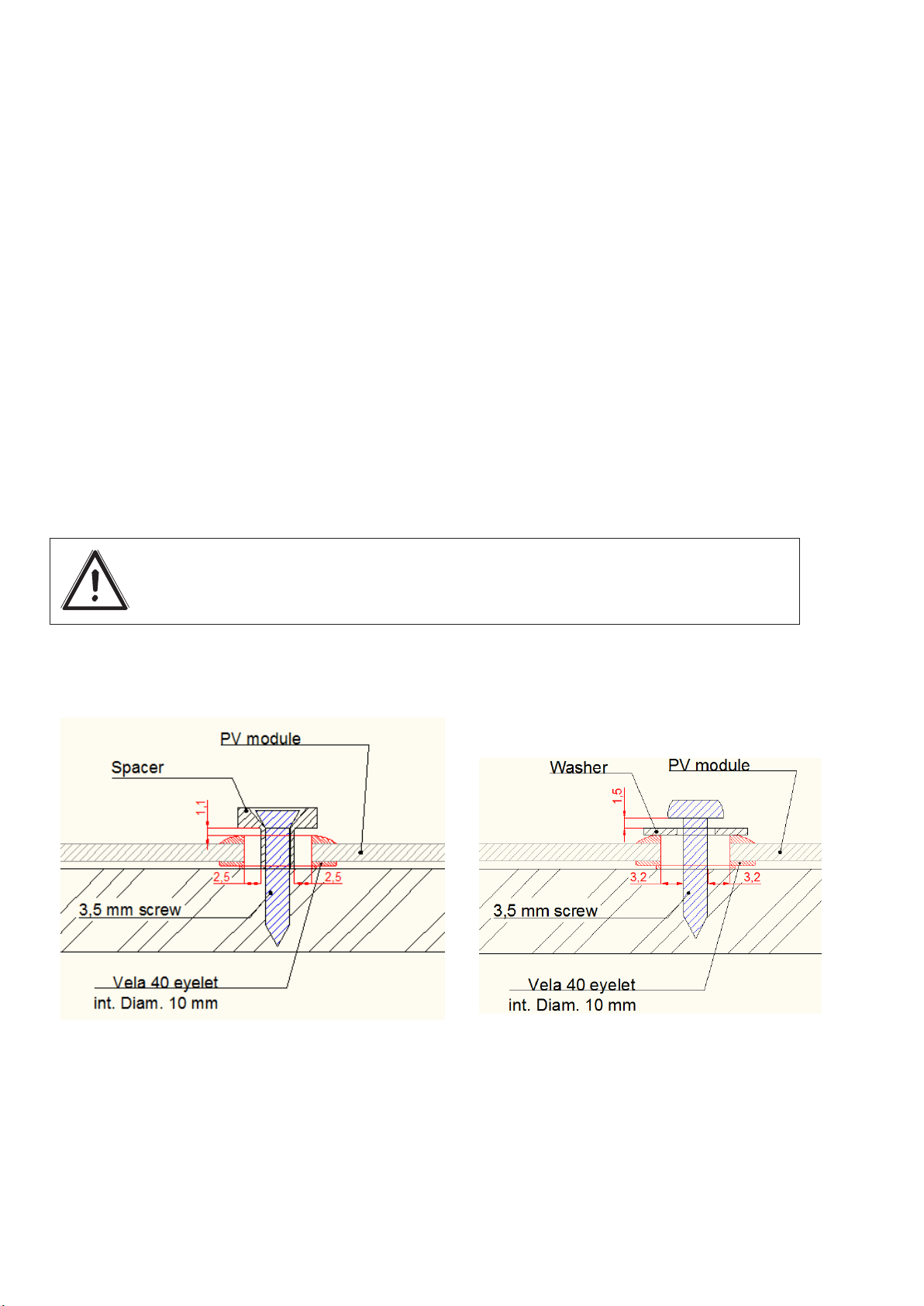
Mounting the panel by means of eyelets
Mounting by means of eyelets is performed using screw or bushing that leave space between
the eyelet and the screw or spacer used for the installation.
The space allows thermal dilation between the module and the fixing system and for a
correct installation this space has to be at least:
1 mm from the top of the eyelet and the fixing system.
2 mm from the internal diameter of the eyelet and the screw
See below an example of a mechanical fixing system using a washer or a spacer and a
screw:
During mounting, avoid applying pressure on the cells or overbidding the panel.
Eyebrow fixing is also suitable for support on non-rigid surfaces (awnings, camper verandas,
camping tents, etc.) using elastic or corded joints for example.
Block the module without leave space for thermal dilation void the guarantee

13
Bonding the panel using double sided adhesive
Bonding using double sided adhesive is indicated when the material of the module and that
of the surface, on which the panel has to be fixed, have similar thermal expansion
coefficients.
Enecom can provide the module with already attached to the back double sided adhesive
stripes or send to you the quantity you need for the installation.
You can fix the panel also with a kind of Velcro called Dual Lock. This system allows you to
remove the panel if necessary, but it is not recommended where high adherence is required.
The following instructions should be followed when using this method:
•
clean the installation surface thoroughly with isopropyl alcohol
•
make sure the surfaces are completely dry after cleaning
•
attach the modules, making sure there are no air bubbles between the
adhesive and the surfaces
•
do not subject the cells of the module to localized pressure during
mounting: this can cause serious damage to the solar cells
Fastening with double-sided adhesive makes it difficult to remove the module
from the surface on which it is glued without damaging it due to the high
adhesion strength that is created between the surfaces. It is therefore
advisable to use this installation method if you do not want to move the
module later and if the installation is final while you are advised to fasten with
dual lock when you need to move the module after installation.
Other installation option
If it is not possible to fix the module as in the two previously-mentioned cases,
please contact Enecom Technical Support who will provide you support
giving instructions on how to proceed with the installation.
Install the panel in a different way than the two descripted without
contacting the technical office and having its permission void the warranty
14
Electrical connections
Connecting several modules together
Several PV modules can be connected to each other in the following ways:
•
in-series connection
•
parallel connection
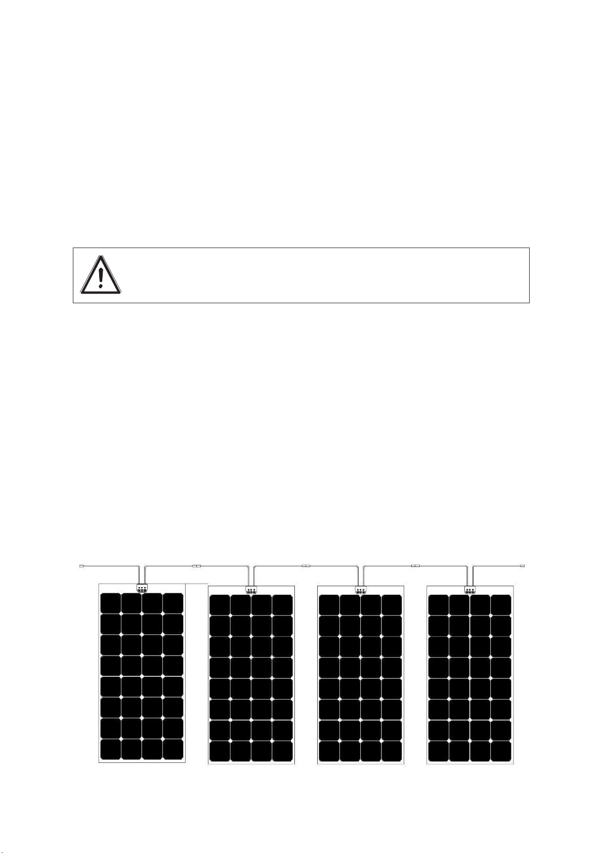
Connection of several modules in-series
For in-series connection, the positive connector (+) of one module must be connected to the
negative connector (-) of the one next to it: in this way, a voltage corresponding to the sum of
the electrical voltages of each individual module will be present between the free connector
of the first module and the free connector of the last module.
∑ VOLTAGE
= CURRENT
This option is not applicable to modules HF20-5-16, HFp20-5-16, HFp40-5-16
with cigarette lighter style socket
15
Modules of the same type can be always connected in series. The connection in series between
different types of modules can be done only after Enecom technician’s authorization.
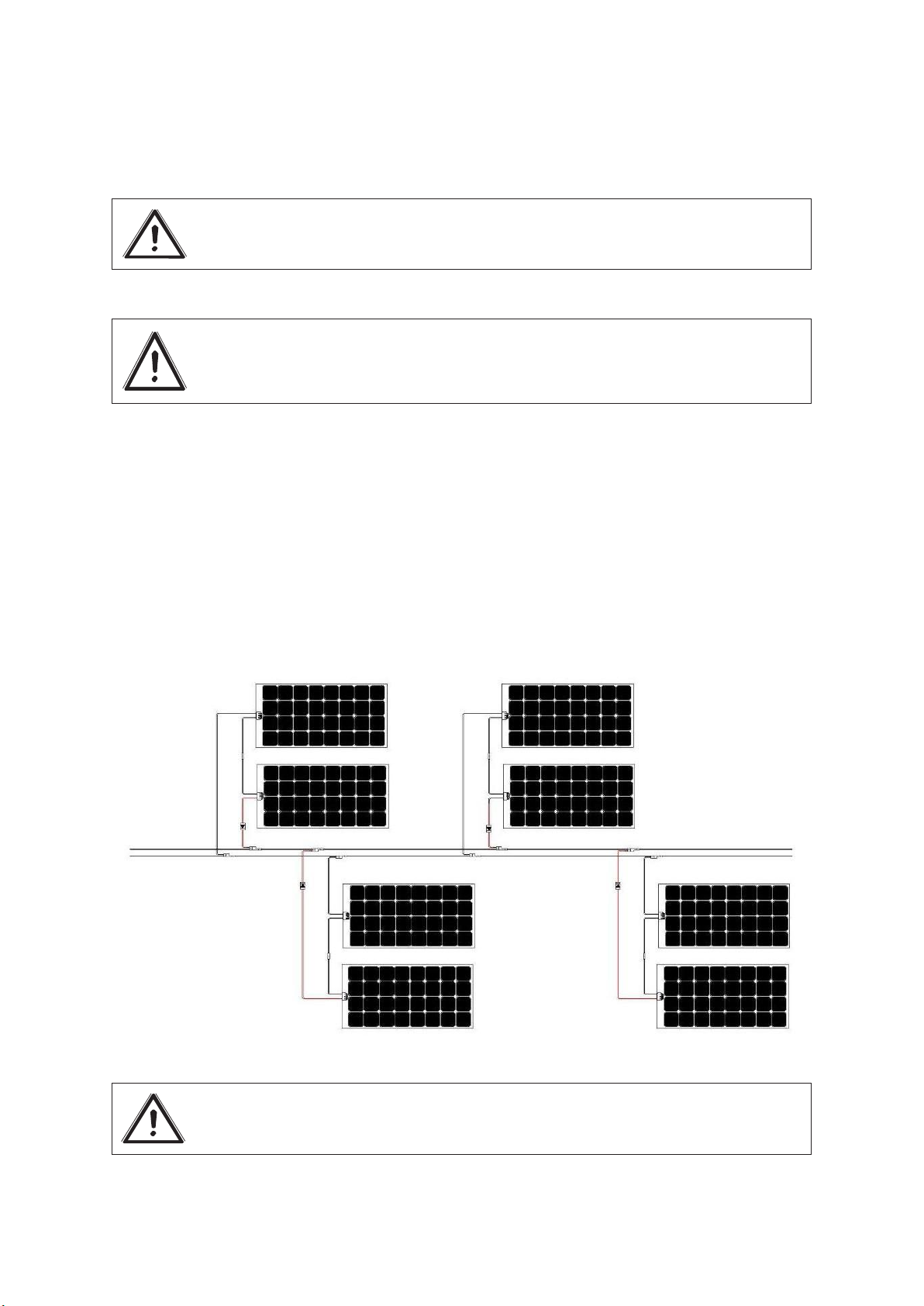
Connection of several modules in parallel
In parallel connection an electrical current is obtained which is the sum of the electrical currents
generated by the individual modules. Establishing a parallel connection requires the use of
additional connectors (parallel connectors) which can be ordered separately from our
accessory range.
VOLTAGE =
∑ CURRENT
Warning! This type of connection is indicated when all modules are
exposed to the sun in the same way. We suggest that the installation of
more than two modules should be performed by a qualified technician.
Warning! All the modules connected in parallel must be identical. It is
also necessary to protect the panels by using blocking diodes placed on
the positive cable of each panel group.
Warning! Wrong connections between the modules void the guarantee.
16
Extension
cables
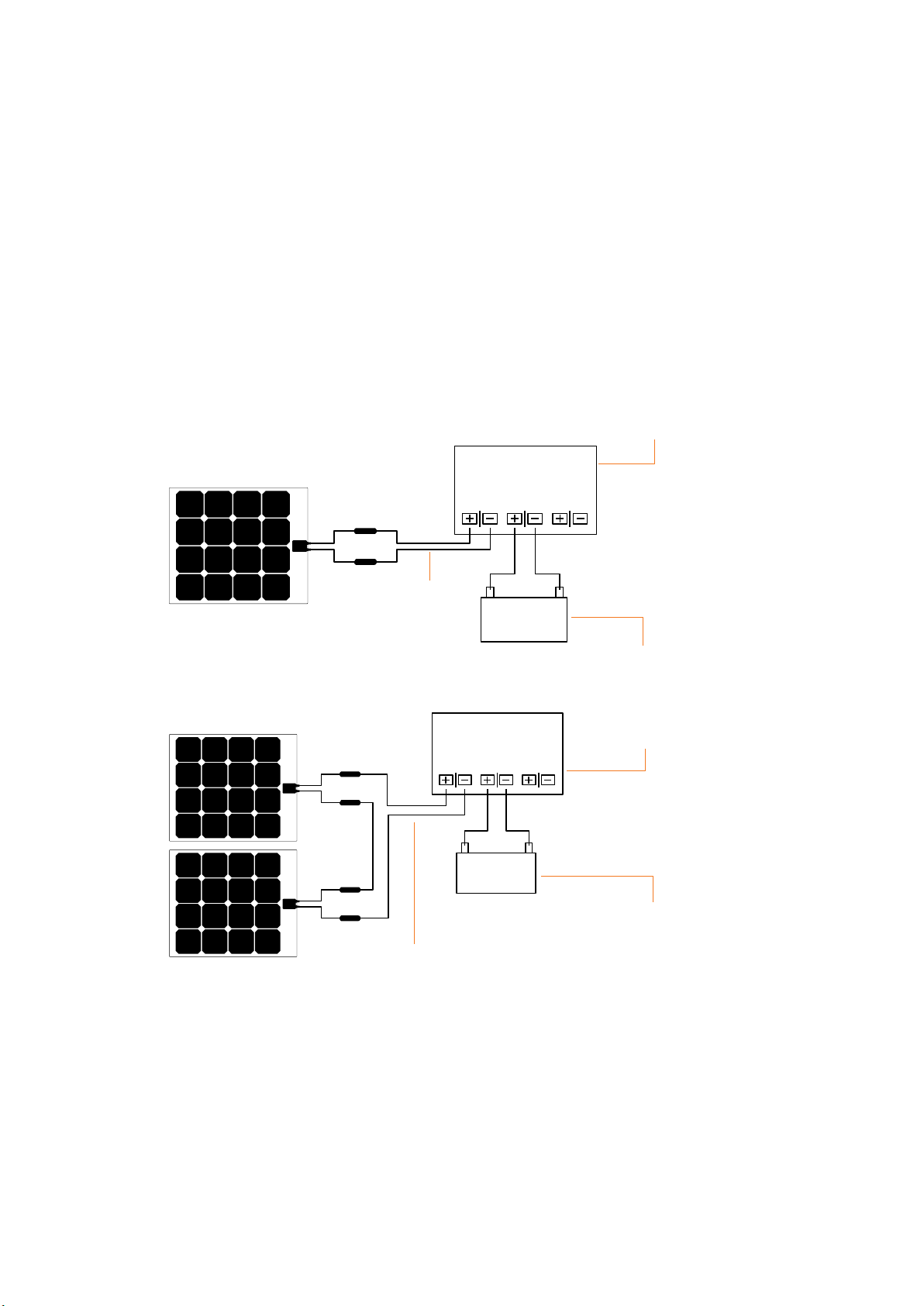
Connecting to an accumulator (battery)
The connection of one or more modules to an accumulator must always be performed by means
of a charge regulator.
The module (or the string of modules) must be connected to the charge regulator and the
accumulator by means of two extension cables.
The charge controller must be chosen according the instruction of its user manual; if the
compatibility is not certain contact Enecom’s technical office. Any erroneous connections to
the solar charger will cause the void of the guarantee and may be a source of malfunction of
the system.
See below some example of connection to an accumulator.
Charge regulator
Accumulator
Charge regulator
Extension
cables
Accumulator
Direct connection is possible only with usage devices that have a built-in battery and charge
regulator.
Modules HF20-5-16, HFp20-5-16 and HFp40-5-16 are suitable for this type of connection by
means of an automobile transformer specific to its device. The transformer is equipped with a
cigarette lighter style plug which is inserted into the module’s socket.

17
Connecting to the electrical network
The connection of one or more modules to the electrical network is not described in this
manual, as it must be performed by a qualified technician because small electrical systems are
subject to specific regulatory constraints and safety regulations.
MAINTENANCE
Photovoltaic modules require very little maintenance because of the absence of moving parts.
Maintenance includes the following:
•
regular cleaning of the module;
•
periodic inspection;
•
electrical performance checks.
Cleaning the module
Dirt accumulated on the upper surface reduces performance and can cause adverse effects
similar to those caused by shade. The problem is more pronounced in areas with high smog
levels or the presence of birds or trees.
The intensity of the effect depends on the opacity of the accumulations (grime, soot, leaves,
bird droppings, etc.). In many cases, rain may reduce or eliminate the accumulation of
impurities on the modules.
Cleaning involves simply washing the module with fresh water or isopropyl alcohol using non-
abrasive sponges. Do not use pressurized water jets.
Inspection
It is a good rule to inspect the photovoltaic system periodically in order to check the condition of
the solar panels and the connections between the devices.
Electrical performance checks
Periodic electrical performance checks help to ensure the proper functioning of the
photovoltaic module: for example, a reduction of the electrical power generated may
indicate an isolated shady area on one or more cells, which can then be rectified to obtain
optimal performance.

18
WARRANTY
The warranty against defects in material and workmanship and the warranty of proper
functioning of the product are given in the document “Enecom Warranty” provided
together with this manual.
CONTACTS
Headquarters
Via Odorico da Pordenone, 28 - 50127 FIRENZE Tel.
+39 055 333017
Fax +39 055 3217162
Prato Operational Unit
Via Siena, 16 - 59013 MONTEMURLO (PO)
Tel. +39 0574 653085
Fax +39 0574 658000
Turin Operational Unit
Via Emilia, 6 - 10099 SAN MAURO TORINESE (TO) Tel.
+39 011 2979165
Tel. +39 011 2976623
Fax +39 011 2742438
Sales department:
info@enecompower.com

CONTATTI

This manual suits for next models
12
Table of contents
Popular Solar Panel manuals by other brands


Ansult
Ansult 019394 operating instructions

Viessmann
Viessmann Vitosol-F Series installation instructions

PHOTOWATT
PHOTOWATT PW72LHT-CB-XF installation manual

iwerkz
iwerkz SolRX instruction manual

EINHELL
EINHELL SO 6-M operating instructions

Photonic Universe
Photonic Universe SWD-FWP-60M instruction manual


 installation manual")

