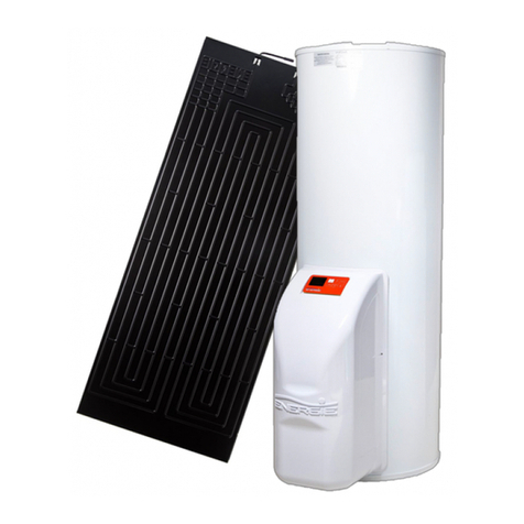
Technical Manual
4
Index
1. INTRO ........................................................................................................... 6
1.1. Symbols..................................................................................................................................6
1.2. Safety Information ................................................................................................................6
1.3. Information.............................................................................................................................7
2. SPECIFICATIONS........................................................................................ 9
2.1. Components ..........................................................................................................................9
2.2. Running Principle ...............................................................................................................10
2.3. Technical Data ....................................................................................................................11
3. TRANSPORT.............................................................................................. 12
4. INSTALLATION.......................................................................................... 13
4.1. Safety and Control Devices ..............................................................................................13
4.1.1. High/Low Pressure Switch.........................................................................................13
4.1.2. Safety Thermostat.......................................................................................................13
4.1.3. Temperature Probe.....................................................................................................13
4.1.4. Protection Against Corrosion (If Applicable)...........................................................13
4.1.5. Expansion Vessel* ......................................................................................................13
4.1.6. Safety Group* ..............................................................................................................13
4.1.7. Pressure Reducing Valve*.........................................................................................13
4.2. Drain pan .............................................................................................................................14
4.3. Positioning ...........................................................................................................................14
4.4. Air Inlet/Outlet Installation .................................................................................................15
4.4.1. Installation without Ducts ...........................................................................................15
4.4.2. Installation with Ducts.................................................................................................15
4.5. Hydraulic Installation..........................................................................................................18
4.6. Condensates .......................................................................................................................19
4.7. Electrical Connections .......................................................................................................19
4.8. Electrical Diagram ..............................................................................................................20
5. CONTROL and PROGRAMMING ............................................................ 21
5.1. Control Panel.......................................................................................................................21
5.2. Keys (Functions).................................................................................................................21
5.3. Display..................................................................................................................................22
5.3.1. Interface........................................................................................................................22
5.3.2. Symbols ........................................................................................................................22
5.3.3. Symbols with Equipment Running............................................................................23
5.4. Start-up of the System.......................................................................................................24
5.5. Operating Modes ................................................................................................................24
5.5.1. Mode ...................................................................................................................25
5.5.2. Mode ..................................................................................................................25
5.5.3. Mode .................................................................................................................25
5.5.4. LAT Mode .....................................................................................................................25
5.5.5. Mode....................................................................................................................26
5.5.6. Chrono scheduling of the heat pump.......................................................................27
5.6. Extra Modes ........................................................................................................................33


