Enerpac B2009 User manual

Repair Parts Sheets for this product are available from the Enerpac
web site at www.enerpac.com, or from your nearest Authorized
Enerpac Service Center or Enerpac Sales office.
1.0 IMPORTANT RECEIVING INSTRUCTIONS
Visually inspect all components for shipping damage. Shipping
damage is not covered by warranty. If shipping damage is found,
notify carrier at once. The carrier is responsible for all repair and
replacement costs resulting from damage in shipment.
SAFETY FIRST
2.0 SAFETY ISSUES
Read all instructions, warnings and cautions carefully.
Follow all safety precautions to avoid personal injury or
property damage during system operation. Enerpac
cannot be responsible for damage or injury resulting from unsafe
product use, lack of maintenance or incorrect product and/or system
operation. Contact Enerpac when in doubt as to the safety
precautions and operations. If you have never been trained on high-
pressure hydraulic safety, consult your distribution or service center
for a free Enerpac Hydraulic safety course.
Failure to comply with the following cautions and warnings could
cause equipment damage and personal injury.
A CAUTION is used to indicate correct operating or maintenance
procedures and practices to prevent damage to, or destruction of
equipment or other property.
A WARNING indicates a potential danger that requires correct
procedures or practices to avoid personal injury.
A DANGER is only used when your action or lack of action may
cause serious injury or even death.
WARNING: Wear proper personal protective gear when
operating hydraulic equipment.
WARNING: Stay clear of loads supported by hydraulics.
A cylinder, when used as a load lifting device, should never
be used as a load holding device. After the load has been
raised or lowered, it must always be blocked mechanically.
WARNING: USE ONLY RIGID PIECES TO HOLD LOADS.
Carefully select steel or wood blocks that are capable of
supporting the load. Never use a hydraulic cylinder as a
shim or spacer in any lifting or pressing application.
DANGER: To avoid personal injury keep hands and
feet away from cylinder and workpiece during
operation.
WARNING: Do not exceed equipment ratings. Never
attempt to lift a load weighing more than the capacity of the
cylinder. Overloading causes equipment failure and
possible personal injury. The cylinders are designed for a max.
pressure of 700 bar [10,000 psi]. Do not connect a jack or cylinder
to a pump with a higher pressure rating.
Never set the relief valve to a higher pressure than the
maximum rated pressure of the pump. Higher settings may
result in equipment damage and/or personal injury.
WARNING: The system operating pressure must not
exceed the pressure rating of the lowest rated component
in the system. Install pressure gauges in the system to
monitor operating pressure. It is your window to what is happening
in the system.
CAUTION: Avoid damaging hydraulic hose. Avoid sharp
bends and kinks when routing hydraulic hoses. Using a
bent or kinked hose will cause severe back-pressure.
Sharp bends and kinks will internally damage the hose leading to
premature hose failure.
Do not drop heavy objects on hose. A sharp impact may
cause internal damage to hose wire strands. Applying
pressure to a damaged hose may cause it to rupture.
IMPORTANT: Do not lift hydraulic equipment by the hoses
or swivel couplers. Use the carrying handle or other means
of safe transport.
CAUTION: Keep hydraulic equipment away from
flames and heat. Excessive heat will soften packings
and seals, resulting in fluid leaks. Heat also weakens
hose materials and packings. For optimum performance do not
expose equipment to temperatures of 65°C [150°F] or higher.
Protect hoses and cylinders from weld spatter.
DANGER: Do not handle pressurized hoses. Escaping oil
under pressure can penetrate the skin, causing serious
injury. If oil is injected under the skin, see a doctor
immediately.
®
®
®
read.eps
®
Instruction Sheet
Air/Hydraulic Booster
B2009, 2009V B3006, 3006V B5003,5003V
L1356 Rev. A 01/03
Index:
English: . . . . . . . . . . . . . . . . . . . . . . . . . . . . . . . . . . . . . . 1-4
Français: . . . . . . . . . . . . . . . . . . . . . . . . . . . . . . . . . . . . . N/A
Deutsch: . . . . . . . . . . . . . . . . . . . . . . . . . . . . . . . . . . . . . N/A
Italiano: . . . . . . . . . . . . . . . . . . . . . . . . . . . . . . . . . . . . . . N/A
Español: . . . . . . . . . . . . . . . . . . . . . . . . . . . . . . . . . . . . . N/A
Nederlands: . . . . . . . . . . . . . . . . . . . . . . . . . . . . . . . . . . .N/A
Portuguese: . . . . . . . . . . . . . . . . . . . . . . . . . . . . . . . . . . N/A
. . . . . . . . . . . . . . . . . . . . . . . . . . . . . . . . . . . . . . .N/A

2
WARNING: Only use hydraulic cylinders in a coupled
system. Never use a cylinder with unconnected couplers.
If the cylinder becomes extremely overloaded,
components can fail catastrophically causing severe personal
injury.
WARNING: BE SURE SETUP IS STABLE BEFORE
LIFTING LOAD. Cylinders should be placed on a flat
surface that can support the load. Where applicable, use a
cylinder base for added stability. Do not weld or otherwise
modify the cylinder to attach a base or other support.
Avoid situations where loads are not directly centered on
the cylinder plunger. Off-center loads produce
considerable strain on cylinders and plungers. In addition,
the load may slip or fall, causing potentially dangerous results.
Distribute the load evenly across the entire saddle surface.
Always use a saddle to protect the plunger.
IMPORTANT: Hydraulic equipment must only be serviced
by a qualified hydraulic technician. For repair service,
contact the Authorized ENERPAC Service Center in your
area. To protect your warranty, use only ENERPAC oil.
WARNING: Immediately replace worn or damaged parts
by genuine ENERPAC parts. Standard grade parts will
break causing personal injury and property damage.
ENERPAC parts are designed to fit properly and withstand high
loads.
3.0 SPECIFICATIONS
Note: Shipping box contains fittings for NPT hook-up. The fitting
with the tapered male threads goes into the 3/8 BSPT air inlet.
Ambient Temperature Range..............-4˚F (-20˚C) to +176˚F (80˚C)
Recommended Oil Temperature ......+59˚F (15˚C) to +131˚F (55˚C)
Minimum Operating Air Pressure ................................40 psi (3 bar)
Maximum Operating Air Pressure..............................125 psi (9 bar)
Air Consumption ..............................................0.95 cu. ft. per stroke
Reservoir Capacity ..............................................................50 cu. in.
Usable Oil Capacity ..........................................................13.4 cu. in.
Maximum Cycle rate ........................................10 cycles per minute
Air Piston Retract Speed (from full extend)
@ 86 psi (6 bar)............................................................Max. 3.2 sec.
Return Spring Force @ Initial Position....................................57 lbs.
Return Spring Force @ Maximum Compression ..............1041 lbs.
Stroke Sensing Position Before Full Stroke ..........................1.04 in.
Sensing Contact Capacity ......................................30 VDC, 3 amps
4.0 INSTRUCTIONS
4.1 General Description
Air operated hydraulic boosters convert low pressure air to high
pressure hydraulic oil for operating hydraulic cylinders, clamps or
similar devices. Primary booster components are, the air piston and
the hydraulic cylinder plunger. Air pressure, into the booster, exerts
a force against the air piston causing it to move forward. The forward
motion compresses the piston return spring and moves the hydraulic
plunger in the oil cylinder. The plunger compresses the oil in the
cylinder developing high pressure at the outlet port.
Pressure intensification is determined by the air piston to hydraulic
plunger ratio. If the booster ration is 20:1 100 psi air pressure will
produce 2000 psi hydraulic pressure. Air pressure of 80 psi will
produce 1,600 psi hydraulic pressure. To determine actual holding
forces, multiply the effective area of a working cylinder by the
hydraulic pressure being produced. The result is holding force
in pounds.
4.2 Selecting Cylinders and Boosters
1. Determine the holding force required for the application.
2. Determine input air pressure available.
3. Determine volume of oil required in the hose or pipe from the
booster to the working hydraulic cylinder or clamping devices.
Note: Any cylinder can be matched with any pump or booster as
long as the pump or booster has enough useable oil capacity (cubic
inches) to transmit and fully extend the cylinder or cylinders.
Your only other consideration is knowing the maximum Hydraulic
Pressure Range (psi) of the selected pump or booster for
determining the "Cylinder Holding Force" of the cylinder or
cylinders.
=÷OIL
Useable Oil
Capacity
Pump or
Booster
TO FIND: Total number of Cylinders Useable Oil Capacity of Pump
that can be used with = (or) Booster oil Output (cu. in.)
Booster or Pump Oil Capacity of Cylinder (cu. in.)
OIL =x
TO FIND: Cylinder Oil Capacity =Cylinder Effective xCylinder Stroke
(cu. in.) Area (sq. in.) (inches)
=x
Force
(lbs) Pump or
Booster
Working
Pressure
TO FIND: Cylinder Holding =Cylinder Effective xHydraulic Working
Force (lbs) Area (sq. in.) Pressure (psi)
Model No. Ratio Oil Per Oil Pressure Max
Piston Stroke Oil at 100PSI Oil
Stroke Output Air Pressure Pressure
B-2009 20:1 5.20 in. 9.30 cu. in. 2000 psi 2500 psi
B-3006 30:1 5.20 in. 6.20 cu. in. 3000 psi 3750 psi
B-5003 50:1 5.20 in. 3.70 cu. in. 5000 psi 6250 psi
®

3
The selected pump or booster will operate at various desired
pressure ranges within its maximum rated capacity. Therefore, the
"Workholding Cylinders" will operate at many desired workholding
forces by merely regulating the hydraulic operating pressure (psi) of
the pumps or boosters.
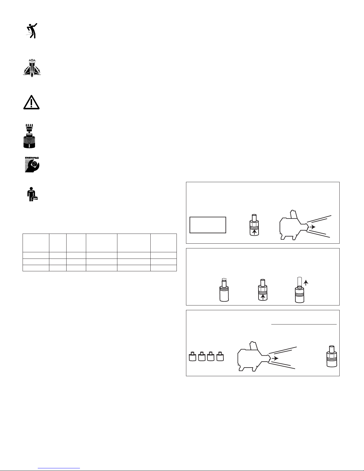
5.0 INSTALLATION
1. Install the booster in a location which is higher than the working
cylinders. The booster can be mounted in the horizontal or one
vertical position. When mounting vertically, the hydraulic output
end (port) must face up.
2. To mount the booster, remove the capscrew and acorn nuts
securing the bracket to the booster.
3. Re-position the booster bracket using any of the six positions
around the circumference of the booster. Be sure all capscrews
are firmly tightened.
4. Install four mounting screws through the bracket and into the
mounting plate (figure 1).
Note: When mounting the booster, the air fill cap and sight gauge
should always remain visible and useable to permit checking and
re-filling the reservoir.
Figure 1
6.0 INCOMING AIR SUPPLY
Compressed air, to the booster, must be clean, dry and lubricated to
protect the booster components. If properly treated air is not
available, install an Enerpac regulator/filter/lubricator in the air line
leading to the booster control valve. The regulator/filter/lubricator
provides the following advantages:
1. Removes dirt and moisture from the air
2. Provides a mist of lubrication in the air supply which protects
control valves and booster internal parts. Filter lubricators use
Enerpac hydraulic oil.
3. Contains an air regulator valve and gauge to adjust air pressure
to the booster.
7.0 AIR AND OIL CONNECTIONS
Caution: Teflon tape is an excellent thread sealer, however,
if not properly applied small pieces can tear loose and
enter the hydraulic system causing restrictions and
potential malfunctions. Use 11/2wraps and leave the 2 threads, at
the end of fitting, without tape.
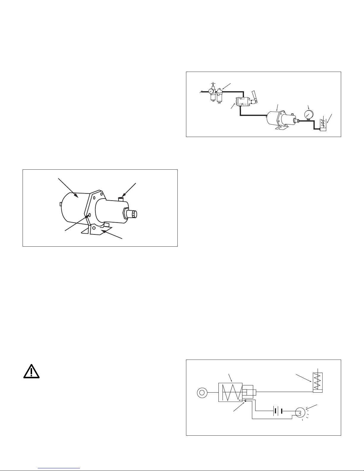
1. A 3-way, 2-position directional control valve (VA-42) is required
to operate booster. Locate the valve within six feet of the
booster, between the regulator/filter/lubricator and the booster
inlet port. Valve port sizes are 3/8” - 18 NPT.
2. Connect the air supply line to the input port on the
regulator/filter/lubricator (3/8” - 18 NPT).
3. Install an air line from the regulator/filter/lubricator outlet port to
the VA-42 valve, port No. 3 (3/8” - 18 NPT).
4. Mount the VA-42 control valve to a solid base. Use the three
mounting holes in the valve body.
5. Connect an air line from the VA-42 control valve, port No. 4, to
the booster inlet port (figure 2). Valve port No. 1 remains open
for exhausting air.
Figure 2
6. Attach a hydraulic line from the booster to the system working
components (ie. cylinder, clamps or valves). Fill booster hydraulic
reservoir with ENERPAC oil, approximately 1.75 quart.
8.0 BOOSTER OPERATION
Booster operating speed depends on factors including working
cylinder strokes, valving, hose lengths and port sizes.
1. Keep hose or pipe lengths reasonably short.
2. Provide clean, dry, lubricated air supply at 40 psi minimum to
125 psi maximum.
3. All hoses, fittings, piping and associated components must be
pressure rated to withstand maximum system pressure.
4. Maintain booster oil level in the reservoir. Check sight gauge
frequently. Repair leaks immediately.
5. Prior to operation, bleed system to remove air trapped in
hydraulic components.
6. Bleeding Hydraulic System
(a) Check booster reservoir level. Fill to capacity.
(b) Activate booster to complete 2 or 3 cycles and pump oil
into entire system.
(c) Loosen a fitting (furthest from booster). Cover fitting with
rags to prevent oil splatter.
(d) Activate booster to full advance, tighten fitting,
retract booster.
(e) Add hydraulic oil to booster reservoir.
7. MAGNETIC SENSOR: The sensor connections are available to
connect optional indicator lights or buzzers which actuate upon
completion of the hydraulic plunger stroke. Figure 3 illustrates
a typical light connection.
Figure 3
Cylinder
Lamp
Booster
Magnetic
Sensor
Cylinder
Gauge
Booster
VA-42
Valve
Filter
Lubrication
Hydraulic Line
53
24
Incoming
Air
Booster
Capscrews
Fill Cap
Mounting Bracket

4
8.1 Operation
1. Position all working components and ensure oil connections
are complete.
2. Adjust air supply to provide required booster pressure.
3. Booster is activated by pulling handle on the control valve.
When handle is released, the booster retracts via return spring.
Working cylinders or clamps also retract unless a shut-off valve
has been installed to maintain pressure beyond the booster.
9.0 MAINTENANCE
1. Frequently check booster reservoir sight gauge to ensure oil
level remains at proper level. Small red circle, in sight gauge, is
maximum level.
2. After system repairs or oil changes, the hydraulics must be bled
to remove trapped air.
(a) Loosen a fitting furthest from the booster.
(b) Activate booster to fully advance the hydraulic plunger.
Tighten the fitting.
(c) Re-fill booster reservoir. If working system components
continue to function erratically or very slow, bleed system,
check for leaks, repair or replace faulty items.
3. Changing Hydraulic Oil
(a) Change intervals are: every 150 hours during normal
operating conditions, every 50 hours under dirty, dusty or
extremely humid conditions.
(b) Place a drain pan under booster outlet port. Remove
hydraulic line. Tip booster to drain oil into the pan.
(c) Re-install hydraulic line, Remove red fill cap and re-fill
reservoir (13/4quart). When oil appears in sight glass red
circle, reservoir is full.
This manual suits for next models
2
Other Enerpac Extender manuals