Enersound CU-12 User manual

Control Unit CU-12 / Interpreter Console IC-12
INTERPRETATION System
User Manual

About this Manual
Read thisuser manual carefully before installing and operating yourEnersound Interpretation System. Use
theequipment only asdescribed to avoid accidental injury, damage or hearing impairment. Also, read safety
warnings carefully. Keep this manual for future reference. If you give this system to someone else,
remember to include this manual.
Safety Precautions
•Make all connections before plugging the unitinto an AC power outlet.
•Hot swapping isprohibited: Never connector disconnect any cables with the system turned on, especially
the25-pin cables. Always turn off the system before plugging or unplugging interpreterunits,
microphones or cables so as not to damage the system.
•Do not leavethe devices in places with high temperatures orhigh humidity.
•Donothandle the powercord with wet hands.
•Keep the devices away from fire and heat sources.
•Donotplace the equipment on an unstable stand. Use appropriate ororiginal packaging providedby the
manufacturer before transporting the system toavoid damaging or breaking it.
•Adequate ventilation is beneficial for better performance and storage of the equipment.
•Keep the system out of the reach of children.
•The CU-12 must be connected to ground via the power cable for safety reasons and to ensure the audio
performance of the system.
•Do not open the CU-12 and/orinterpreterconsoles. There are no user serviceable parts inside.
•Before using this product with a pacemaker or other medical device, consult your physician or the
manufacturer of your pacemaker or other medical device.
•Using thisproduct at a loud volume or over a prolonged period of time can lead to permanent hearing
damage.
•Reduce the volume to its lowest setting before use.
•When using XLR microphone inputs, connect only microphones that can accept 48Volt Phantompower;
otherwise, there may be riskof damage, injury, fire or explosion.
•When using a mobile phone near thisproduct, noise maybe produced, but this is nota malfunction.Keep
mobile phones as faraway as possible from the product.
•To clean, be sure to first switch off and unplug the CU-12 from the power outlet, then wipe with a dry
cloth. When extremely dirty, use a soft cloth dampened in neutral detergent. Never use benzene, thinner
or chemically-treated towels, which may damage the product’s finish.
•Only use Enersound approved cables to connect the system.Do notuse any accessory not recommended
by the manufacturer.
•A maximum of 11 sets of IC-12 can beconnected in one system. The cumulative cable length should not
exceed 70 meters. For specific requirements,please contact Enersound at 1 800-644-5090 or
support@enersound.com.
•Service must be performed by authorized technicians only.For service, please contact your local
distributor or Enersound at 1 800-644-5090 or support@enersound.com.
•Turn off the power supply and unplug the equipment from the power supply in case the equipment is not
in use for a long time.
Please register the product within 30 days of purchase. To Register Product:
1) Go to www.enersound.com/registration.html
2) Follow instructions to complete the online product registration form.

CAUTION
RISK OF ELECTRIC SHOCK
DO NOT OPEN
TO REDUCE THE RISK OF ELECTRIC SHOCK, DO NOT
EXPOSE THIS EQUIPMENT TO RAIN OR MOISTURE.
CAUTION:
To reduce the risk of electric
shock, DO NOT open covers, no useable
serviceable parts inside. Refer servicing to
qualified service personnel only
This label may appear on the bottom of the unit due to space limitations.
The lightning flash with an arrowhead symbol
and an equilateral triangle is intended to alert the
user of the presence of uninsulated dangerous
voltage within the product enclosure that may
be of sufficient magnitude to constitute a risk
of electric shock.
The exclamation mark within an equilateral
triangle is intended to alert the user of the
presence of important operating and maintenance
(servicing) instructions in the literature
accompanying the appliance.
WARNING:
To avoid fire or shock hazard, do
not expose units to rain or moisture.
Attention: Installation should be performed by qualified
service personnel only in accordance with the National
Electrical or applicable local codes.
Power Disconnect: Units with or without ON - OFF
switches have power supplied to the unit whenever the
power cord is inserted into the power source; however,
the unit is operational only when the ON - OFF switch
is in the ON position. The power cord is the main
power disconnect for all units.

INDEX
1.
System Introduction
1
2.
Product Introduction
2
2-1 Control Unit CU-12 2-3
2-2Interpreter Console IC-12 4-5
3.
System Installation
6-7
4.
System Operation
8-9
4.1 Open Mode 8-9
4.2 Lock Mode 9
5.
Technical Data
10
6.
System Mounting Instructions
11
7.
Limited Warranty Statement
11
Remarks:
Enersound reserves the right to modify the products and its specifications without notice.

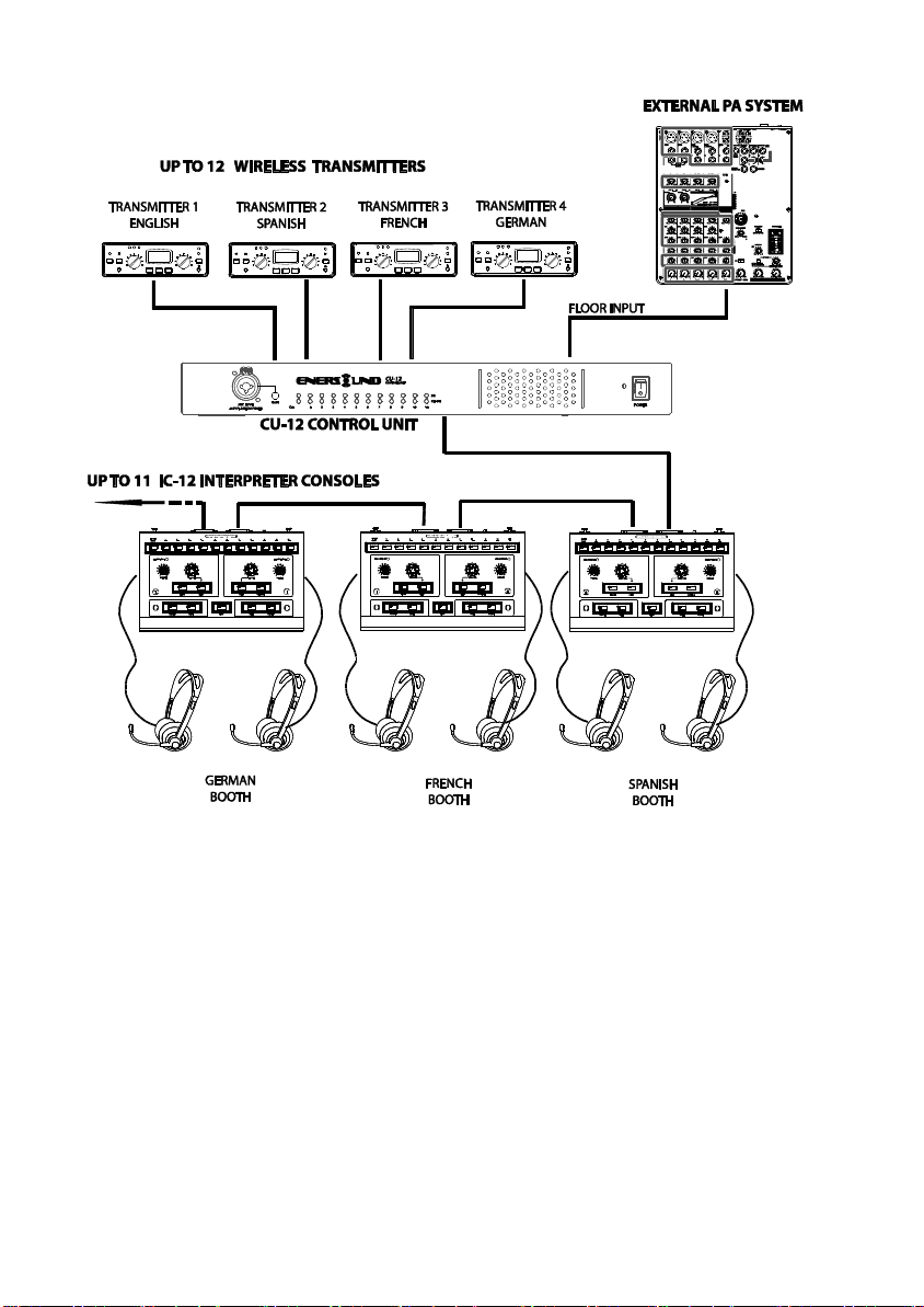
1.System Introduction
•The Enersound CU-12 Control Unit works as a main unit to provide power, input and output interface,
and control for up to 11 dual interpreter consoles. It allows up to 22 interpreters to perform simultaneous
interpretation for a maximum of 11 target languages plus one floor (original) language.
•The Enersound IC-12 is a 12-channel dual interpreter console with relay capabilities. It allows two
interpreters to work together. Interpreters can choose either floor channel to listen to the speaker and
perform direct interpretation or choose the relay mode when the interpreter does not understand the floor
language and listen to the interpretation from a different booth in a language that this interpreter can
understand.
•The IC-12 also allows interpreters to select the outgoing channel depending on the language they are
interpreting into (two-way interpretation), switch on/ off and mute their microphone, and control the
headphone volume.
•The system features a security lock that prevents two interpreters to select the same outgoing channel at
the same time.
•The product is a professional, easy plug and play, stand-alone system that can be integrated with most
infrared (IR) or radio frequency (RF) language discussion systems.
1

2. Product Introduction
2-1 Control Unit CU-12
1. Microphone Input: This XLR and ¼” (6.3mm) combination socket provides +48V Phantom
power to a microphone with balanced XLR or unbalanced 6.3mm connector. The input signal
will be mixed with the floor channel (CH0). Note: Since this input provides +48V Phantom
power, make sure that the microphone you intend to connect can support this voltage. Do not
connect any other equipment or adapter since damage may occur. Never use unbalanced XLR
connectors (Pins 1 and3 connected).
2. Gain: Adjusts microphone input sensitivity. The range is ±10dB.
3. Active Channel Indicator: Lights to indicate that the corresponding channel is active. Flashes to
indicate the corresponding channel is in standby.
4. Audio Level Indicator:The brightnessofthis LEDindicatesthesignallevelof thecorresponding
channel.
5. Power On Indicator (Red).
6. Power Switch: Select “I” to turn on the system, and select “0” to turn it off.
7. Power Supply Socket (3-Prong) with built-in fuse, T2A/250V.
8. DCPowerOutput:TheCU-12includes 12DCpoweroutputs(+15V/500mA)forcertainwireless
transmitters in specific applications (not required in most applications).
9. Interpreter Console Interface (D-sub 25pin socket):11 interpreter consoles IC-12 can be
connected in a daisy chain.
10. Record Input Connector (RCA): External audio signals will be mixed with the floor (CH0) for
recording.
11. Record Output Connector (RCA): Connects to recording equipment. The floor signal (CH0)
mixed with REC. IN will be recorded.
100-
240VAC5
0
-
60Hz
Max.for120W
FUSE:T2A/250
V
7 8 11 12 13 14 15 16 17 18
1 2 3 4 5 6
PowerForWirelessTransmitter12V
300mA
INTERPRETER’S
CONSOLE
9 10 12 13
OUTPUT
ORIGINAL
INPUT
SLOWGND
ALARM
OUT IN
2

12. Floor (CH0, floor channel) Output (RCAx2/symmetrical output): Floor (CH0) balanced output
with RCA connecters.
13. Outgoing Language Channel Audio Outputs: Channels 0 to 11, where CH0 is floor and channels
1 to 11 correspond to the target languages. These analog audio outputs allow connection of the
CU-12toany wireless languagedistributionsystems (IR orRF). Notice:any unoccupied channel
will be fed with CH0 (floor) channel.
14. Floor (CH0) Volume Control: This potentiometer adjusts the floor (CH0) sensitivity. The range
is ±10dB.
15. Floor Input Jack (Also called “Original”) (CH0): This 1/4–inch (6.3mm) balanced socket needs
to be connected to an outputofa conference system or PA as the floor signal of the interpretation
system.
16. AlarmSound Input:This1/4–inch(6.3mm)jack/unbalancedinputallowstoconnectaudiofrom
an emergency or alarm system.
17. Slow Output: When a Slow Key on the IC-12 is activated, this slow output will generate a 1-
second12Vpulseactivatingthe externalnotification systemtorequestthelecturertoslowdown.
18. Alarm Control Input: Connecting Alarm Ctrl. and GND together, will activate alarm procedure.
Allchannelswillreceivealarmsignal,andindicatorLEDwill changefromLight-On to Flashing.
Note: This is not intended to replace any emergency system and is not licensed or certified as an
emergency system. Please check with your local authorities about your required emergency
procedures and equipment.
13
14
15
16
17
18
3

2-2 Interpreter Console // IC-12
19. CLEAR/ ENTER Key:
In OPEN Mode (See 28 below), it serves as the CLEAR key to clear the active channel of the
interpreter console. When the console is not going to be used and an output channel had been
selected, then push the ENTER key to deselect active channel.
In LOCK Mode (See 28 below), it serves as the ENTER key to set the active channel of the
interpreter console (when the MODE switch is in Lock Mode, and the Set switch is in the ON
position).
20. Outgoing Channel Selector:
In OPEN Mode, it allows the interpreter to select the desired outgoing channel as long as it is not
occupied by another booth. When a channel is selected the corresponding key light goes green.
When attempting to select an occupied channel, the light will flash red.
Note: If the microphone is OFF, the active channel will be released if an interpreter from another
booth selects the same channel.
Relay Channel Selector: It allows the selection of the incoming channel for the interpreter to
listen when pressing the Relay key.
21. Headphone Volume Control (VOLUME A, VOLUME B): It is used to adjust the volume of the
headphones.
4

22. RelayInterpretationKey(RELAY):Whentheinterpreterdoesnotunderstandthefloorlanguage,
they can press the Relay key to listen to another interpreted language from another booth. The
channel will be selected through the Relay Channel Selector (See 21 above).
23. Floor Channel Key (FLOOR): The interpreter presses it to listen to the original floor language
(the audio from CH0).
24. Mute Key (MUTE): It is used to momentarily mute the microphone when the interpreter needs
to cough, for example. When released, the microphone returns to its active status.
25. MIC ON/OFF Key (MIC A ON/OFF, MIC B ON/OFF): Press it to turn the microphone on, the
light indicator will be on. Press it again to turn the microphone off. Only one microphone at a
time can be active per console (Microphones A and B will override eachother).
26. SLOW Key: When this function is installed, it allows the interpreter to request the speaker to
slow down.
27. Set Switch (SET): It is used only for the Lock Mode toprogram the desired outgoingchannel. In
Open Mode it should be in OFF position.
28. MODE Switch (OPEN / LOCK): The MODE switch needs to be selected before powering on
the system. In OPEN mode an interpreter can activate any channel at any time as long as it is not
occupied. In LOCK mode the outgoing channel is pre-set .Only one outgoing channel will be
programmed per console (setting procedure: refer to System Installation and System Operation
sections for more details).
29. XLR Microphone Input: Each interpreter unit includes 2 balanced XLR microphone input
sockets with +48V Phantom power. Note: Since this input provides +48V Phantom
power, make sure that the microphone you intend to connect can support this voltage. Do not
connect any other equipment or adapter since damage may occur. Never use unbalanced XLR
connectors (Pins 1 and 3 connected).
30. Input interface (INPUT):This 25-pin male connectorisused tointerconnect interpreterunits and
a control unit via 25-pin cables.
31. Output Interface (OUTPUT): This 25-pin female socket is used to interconnect interpreter units
via 25-pin plugs.
32. Record Interface (REC OUT): This 3.5mm stereo jack is used to record the interpretation
(Available on both left and rightsidesof the Interpreter Console).
33. Microphone Input (MIC IN): This 3.5mm stereo jack is used to connect the interpreter’s headset
microphone (Available onboth left and right sides of the Interpreter Console).
34. Earphone Output (EARPHONE): This 3.5mm stereo jack is used to connect the interpreter
headsets’ earphones (Available on both left and right sides of the Interpreter Console).
29
29
30
31
33
34
35
5
3. System Installation
All consoles are connected via a D-Sub 25-pin cable in a daisy chain. On the rear panel of each IC-
12 interpreter console, there are two 25-pin D-Sub connectors, “INPUT” (Male) and “OUTPUT”
(Female).
1. Connect the plug (male end) from the 25-pin cable to the Control Unit CU-12. Then connect the
socket (female end) from the 25-pin cable to the “INPUT” on the first Interpreter Console. After
that, connect the plug of the second 25-pin cable to the “OUTPUT” of the first Interpreter Console
and the socket to the “INPUT” of the next Interpreter Console.
2. Follow the same procedure until all interpreter consoles are connected. A maximum of 11
interpreter units can be connected, allowing up to 22 interpreters to perform simultaneous
interpretation for a maximum of 11 target languages plus one floor (original) language. Each
Interpreter Console accommodates two interpreters to work in pairs for the same language
combination in the same booth.
Note: Extension cables can be used between Interpreter Consoles and/or Control Unit. Always
use 25-pin high quality cables provided or approved by the manufacturer.
MICROPHONEOUTPUT
CHANNEL
6
(Also called ORIGINAL INPUT)

3. Connect the interpreter’s microphones and stereo headsets in their corresponding jacks.
Then turn the headphone volume control all the way down on each interpreter console.
4. Plug a line level audio signal from the floor language source into the Floor Input ¼’’ Jack
on the rear panel of the Control Unit (Also called ORIGINAL INPUT). Make sure there is
audio coming from this source for testing purposes.
5. Assign a language to each output channel. Example: CH1 is English, CH2 is Spanish, CH3
is French. For each console, we recommend attaching self adhesive or magnetic labels
above the corresponding outgoing channel switch with the names of the two languages
used in that specific console for easy visualization.
6. Connect any RF (FM) or IR wireless transmitter for language 1 to the CH1 output jack on
the control unit. Do the same for all the other channels to be used. Set up the transmitters
according to its instructions. If using Enersound T-500 FM transmitters, connect each
channel output on the IC-12 control unit to the INPUT 1 or INPUT 2 of the corresponding
T-500 Transmitter using either an RCA male to ¼” plug cable (Input 1 on transmitter ) or
RCA to RCA cable (Input 2 on transmitter). Important: INPUT 1 switch on T-500
transmitter must be set to “LINE”. Use one FM T-500 transmitter per language.
7. Plug the control unit’s line cord into an AC power outlet (100 to 240 V, 50-60Hz) and turn
on the control unit.
8. In Open Mode, (make sure the Mode switch is in open position and the Set switch is in the
off position) select the desired outgoing channel on each interpreter console. In Lock
Mode, the outgoing channel is preset. (See 4. System Operation below).
9. On each interpreter console, select the FLOOR channel key so the interpreter can listen to
the floor audio for normal interpretation or the RELAY key for relay interpretation when
the interpreter does not understand the language spoken on the floor.
10. Have the interpreters who will be using the consoles to listen to the headphones and slowly
turn up the volume until the Floor audio is at the lowest comfortable level.
11. Turn the interpreter microphone on by pushing its Mic On/Off button.
12. Have the interpreter speak into the microphone at a natural level. A microphone headset is
recommended to maintain a constant distance between the interpreter’s mouth and the
microphone.
13. Ensure the audio indicator for that specific channel on the control unit is flashing and you
are able to hear the signal with a receiver. Adjust the transmitter input level control if
necessary.
4
Place the microphone at the corner of the
mouth so that it rests at about 1 inch away
from the face. This will avoid noises
generated from the interpreter’s breathing
and air blown while speaking.
Do not place it in front of the mouth!
7

4. System Operation
4-1 Open Mode
This is the most widely used mode and will suit the majority of your interpretation needs.
For the system to operate in Open Mode, the Mode switch must be in the OPEN position and
the Set switch must be in the OFF position.
When the interpreter selects the desired outgoing channel, the light indicator will turn green
while the channel is not occupied. If the key indicator flashes red when pressing the outgoing
channel key, it means that the channel is occupied by another unit and the interpreter has to wait
until the other interpreter occupying the channel either releases the channel or turns off their
microphone. Note: If the microphone is OFF, the active channel will be released if an interpreter
from another booth selects the same channel.
If there is a need to deselect the active outgoing channel, press the Enter/ Clear key.
When the output channel is selected, the interpreter must push the MIC ON/OFF key to
activate or deactivate the microphone. To momentarily mute the microphone, the interpreter
can press and hold the “MUTE” key.
If the SPEAK SLOWLY function is correctly installed with additional external equipment, when the
speaker speaks toofast for the interpreter to follow,the interpreter can press the “SLOW” key to
remind the speaker to slow down. A 1 second 12V Pulse will come out from the control unit CU-
12 to activate the external notification system.
The example below will help to explain how to operate the system in a conference setting
using interpreter consoles in open mode with “direct” and “relay” interpretation.
Note: It is always necessary to utilize a PA System (Sound System) in conjunction with the
interpretation system so that any speech to be interpreted can be sent to the interpretation
consoles via the FLOOR input.
•Event type: Trilingual conference in the U.S.A with direct and relay interpretation
•Main language: English
•Other languages: Spanish and French
•Number of interpretation booths: 2 (one interpreter console IC-12 per booth)
•Booth #1: “Spanish” Booth from “English into Spanish” and from “Spanish into English”
•Booth #2: “French” Booth from “English into French” and from “French into English”
•Assigned channels: English=CH1 Spanish=CH2 French=CH3
Scenario 1- The speaker talks in English or the audience asks a question in English:
The Spanish interpreter will perform direct interpretation into Spanish. Her outgoing channel
selector should be in CH2 (Spanish) so that her voice is routed to the Spanish channel.
She will listen to the original floor audio; therefore, her “FLOOR” Channel Key should be
selected.
The French interpreter will perform direct interpretation into French. Her outgoing channel
selector should be in CH3 (French) so that her voice is routed to the French channel.
She will listen to the original floor audio; therefore, her “FLOOR” Channel Key should be
selected.
Scenario 2- The speaker talks in Spanish or the audience asks a question in Spanish:
The Spanish interpreter will perform direct interpretation into English. Her outgoing channel
selector should be in CH1 (English) so that her voice is routed to the English channel. She
will listen to the original floor audio; therefore, her “FLOOR” Channel Key should be
selected.
8
8

The French interpreter will perform relay interpretation into French. Her outgoing channel
selector should be in CH3 (French) so that her voice is routed to the French channel. Since
she does not understand Spanish, she will listen to the relay audio (English) from the other
interpreter booth. Her “RELAY”Channel Key should be selected and the rotary relay
channel selector should be in CH1 (English). Note: If the French interpreter understands
Spanish, she can perform direct interpretation into French listening directly from the “Floor”.
Scenario 3- The speaker talks in French or the audience asks a question in French:
The Spanish interpreter will perform relay interpretation into Spanish. Her outgoing channel
selector should be in CH2 (Spanish) so that her voice is routed to the Spanish channel. Since
she does not understand French, she will listen to the relay audio (English) from the other
interpreter booth. Her “RELAY” Channel Key should be selected and the rotary relay
channel selector should be in CH1 (English). Note: If the Spanish interpreter understands
French, she can perform direct interpretation into Spanish listening directly from the “Floor”.
The French interpreter will perform direct interpretation into English. Her outgoing channel
selector should be in CH1 (English) so that her voice is routed to the English channel.
She will listen to the original floor audio; therefore, her “FLOOR” Channel Key should be
selected.
4-2 Lock Mode
This mode is used in special cases when there is one-way interpretation (i.e. the interpreter
will always interpret into one foreign language).
Each Interpreter Console IC-12 must be preset with a unique outgoing channel before being
used. The procedure is as follows:
a. Slide the Mode switch on all the interpreter consoles to the Lock position.
b. Make sure all connections are correct, and power on the control unit CU-12.
c. Slide the “SET” switch on the rear panel of the Interpreter Console to the “ON” position.
The “ENTER” light indicator on thatunit will start flashing. The available channels indica-
tors will turn RED. Only one unassigned channel can be activated per console.
d. Press one of the available outgoing channel keys and then press “ENTER” to save the
selection. For example: if you want this unit to be assigned to CH1, press the outgoing key
“1”. Then the indicator on the key will change to green. Press the “ENTER” key to save
your selection.
e. Turn the “SET” switch to the “OFF” position. The “ENTER” indicator will turn off and the
output channel selecting procedure will be completed.
f. Repeat the same procedure (Steps c~e) to assign all the Interpreter Consoles.
To Cancel Selected Output Channel (only for LOCK mode)
a. Turn the “SET” switch to the “ON” position.
b. Push the “ENTER” key for 3 seconds. Then all Outgoing Channel Indicators will turn off.
c. Turn the “SET” switch to the “OFF” position. The Console will be reset to factory default
setting.
9

5. Technical Data
System environmental Conditions
TransportTemp -40○C ~ +70○C
OperationalTemp. 0
○
C~+45
○
C Max.
Relative humidity <95%
Control Unit CU-12 Technical Data
Power supply 110-240Vac
System consumption 90W
DC power output +15V/0.3A x12
D-SUB power output DC+15V/2A
LineIn sensitivity -30dB±2dBLEVEL VR atMAX.
Alarm In sensitivity -20dB±2dB
MIC In sensitivity -51dB±2dB Gain VR at MAX.
Alarm Ctrl Shorted to GND
Slowoutput +12V, 1sec Pulse.
CH0~CH11 output level 180mV±20mV
CH0 balance output level 85mV-GND85mV±10mV
REC OUT output level 170mV±15mV
REC INinput level -25dB±2dB
Protocol RS-485
Dimension (LxWxH) 421x213x44mm
Color Gray
Weight 2.65Kg.
Interpreter Console IC-12 Technical Data
Unit power DC+15V
Unit power consumption 100mA±10mA
MIC sensitivity -45dB±2dB
XLR MIC sensitivity -45dB±2dB
Earphone max output level 30mW+30mW at 32Ω,
REC OUT output level 140mV±10mV
Protocol RS-485
In/Out interface D-Sub 25P plug and socket
Dimension(LxWxH) 330x206x57mm
Color Gray
Weight 2.5Kg
10

6. System Mounting Instructions
A pair of rack mount brackets are included with the CU-12 (38), unscrewthe side screws (39), then
fasten the brackets with these screws and put the CU-12 in the rack, finally install the unit onto the rack
with 4 screws (40).
7.
Limited Warranty Statement
Enersound warrants its Interpretation System: CU-12, IC-12 to be free from defects in workmanship and
material under normal use and conditions for one year from the date of purchase from an authorized
dealer. All other products and accessories are warranted for 90 days from date of purchase. This warranty
is only available to the original end purchaser of the product and cannot be transferred. If the product is
determined to be defective, Enersound will repair or replace it, at its discretion, at no charge. Customer
must pay for shipping. This warranty is void if damage occurred because of misuse or if the product has
been repaired or modified by anyone other than a factory-authorized service technician. Warranty does
not cover normal wear and tear on the product or any other physical damage unless the damage was the
result of a manufacturing defect.
Enersound has no control over the conditions under which this product is used. Therefore, the company
disclaims all warranties not set forth above, both express and implied, with respect to the Interpretation
System, including but not limited to any implied warranty of merchantability or fitness for a particular
purpose. Enersound products manufacturer, distributors and/or dealers shall not be liable to any person
or entity for any medical expenses or any direct, incidental or consequential damages caused by any use,
defect, failure or malfunction of the product, whether a claim for such damages is based upon warranty,
contract, tort or otherwise. The sole remedy for any defect, failure or malfunction of the product is
replacement of the product. No person has any authority to bind Enersound to any representation or
warranty with respect to the Enersound Interpretation System. This warranty gives you specific legal
rights, and you may also have other rights which vary from state to state. Some states do not allow
limitations on how long an implied warranty lasts, and the exclusion or limitation of incidental or
consequential damages, so the above limitation may not apply to you. This warranty applies to products
sold only within the United States of America and does not cover products sold AS IS or WITH ALL
FAULTS. For products sold outside the U.S., please consult with your local dealer about the terms and
conditions applicable in your country. Proof of purchase in the form of a bill of sale, invoice number or
receipted invoice, which is evidence that the unit is within the warranty period, must be presented to
obtain warranty service. If you experience difficulty with your interpretation System, send an email to
support@enersound.com with your name, address, phone number and a complete description of the
problem. We will respond to you as soon as possible and if it isnecessary to return the product for service,
your Customer Service Representative will give you a Return Authorization Number (RAN) and shipping
instructions. For more information, visit www.enersound.com. You may also call 1-305-731-2416 or our
toll-free number 1-800-644-5090 within the U.S.
©2013 Enersound. All rights reserved.
11

CU-12 / IC-12 Version 2.1
This manual suits for next models
1
Table of contents
Other Enersound Microphone System manuals


