EnerSys Alpha Micro 100 User manual

Alpha Micro
100 UPS
Technical Guide: 017-220-J0
Effective:09/2020


Alpha®Micro 100 UPS
Installation and Operation Manual
For technical support, contact Alpha Technologies:
Canada and USA: 1-888-462-7487
International: +1-604-436-5547
Alpha shall not be held liable for any damage or injury involving its enclosures, power
supplies, generators, batteries, or other hardware if used or operated in any manner or
subject to any condition inconsistent with its intended purpose, or if installed or oper-
ated in an unapproved manner, or improperly maintained.
Photographs contained in this manual are for illustrative purposes only. These photo-
graphs may not match your installation.
NOTE:
Operator is cautioned to review the drawings and illustrations contained in this manual
before proceeding. If there are questions regarding the safe operation of this powering
system, contact Alpha Technologies or your nearest Alpha representative.
NOTE:
NOTE:
Copyright
Copyright © 2020 Alpha Technologies Ltd. All rights reserved. Alpha is a registered trademark of Alpha Technologies
Services, Inc.
No part of this documentation shall be reproduced, stored in a retrieval system, translated, transcribed, or transmit-
ted in any form or by any means manual, electric, electronic, electromechanical, chemical, optical, or otherwise
without prior explicit written permission from Alpha Technologies.
This document, the software it describes, and the information and know-how they contain constitute the proprietary,
confidential and valuable trade secret information of Alpha Technologies, and may not be used for any unauthorized
purpose, or disclosed to others without the prior written permission of Alpha Technologies.
The material contained in this document is for information only and is subject to change without notice. While
reasonable efforts have been made in the preparation of this document to assure its accuracy, Alpha Technologies
assumes no liability resulting from errors or omissions in this document, or from the use of the information contained
herein. Alpha Technologies reserves the right to make changes in the product design without reservation and with-
out notification to its users.

3017-220-J0 Rev C
Table of Contents
1. Safety....................................................................................................................................7
1.1 Safety Symbols.................................................................................................................... 7
1.2 Electrical Safety ................................................................................................................... 8
1.3 General Warnings and Cautions.......................................................................................... 8
1.4 Certications and Compliance ............................................................................................. 9
2. Introduction.........................................................................................................................10
2.1 Product Overview............................................................................................................... 10
3. Specications......................................................................................................................12
4. Site Planning.......................................................................................................................14
4.1 Safety Precautions............................................................................................................. 14
4.2 Electromagnetic Compatibility (EMC) Requirements......................................................... 14
4.3 Mounting Options for the Alpha Micro 100......................................................................... 14
5. Inspection............................................................................................................................15
5.1 Packing Materials............................................................................................................... 15
5.2 Check for Damage............................................................................................................. 15
5.3 General Receipt of Shipment............................................................................................. 15
6. Unpacking the Alpha®Micro 100.........................................................................................16
7. Installation...........................................................................................................................17
7.1 Transporting and Lifting...................................................................................................... 17
7.2 Mounting Options............................................................................................................... 17
7.3 Wiring the Alpha®Micro 100............................................................................................... 21
7.4 Installing and Wiring the Batteries...................................................................................... 22
8. Theory of Operation............................................................................................................27
8.1 Block Diagram.................................................................................................................... 27
8.2 Modes of Operation............................................................................................................ 27
9. Operating the Alpha®Micro 100..........................................................................................31
9.1 Switching the Alpha Micro 100 On and O ........................................................................ 31
9.2 Operating Modes................................................................................................................ 32
9.3 Control Parameters............................................................................................................ 32

017-220-J0 Rev C4
9.4 Battery Charging Options................................................................................................... 34
9.5 Operating via the Communication Module (Intranet or Internet)........................................ 37
9.6 Alpha UPS Monitor Interface: Communication via USB..................................................... 58
9.7 HyperTerminal Interface..................................................................................................... 61
10. Peukert Number................................................................................................................73
10.1 Introduction ...................................................................................................................... 73
10.2 Determining the Peukert Number..................................................................................... 73
10.3 Using the Equation........................................................................................................... 74
10.4 Using the Spreadsheet..................................................................................................... 75
11. Maintenance......................................................................................................................76
11.1 Updating the Micro 100 Firmware (no Communication Module)...................................... 76
11.2 Testing and Replacing the Batteries................................................................................. 78
11.3 Preventative Maintenance................................................................................................ 80
12. Troubleshooting ................................................................................................................81
13. Warranty and Service Information ....................................................................................82
13.1 Technical Support............................................................................................................. 82
13.2 Warranty Statement......................................................................................................... 82
13.3 Limited Hardware Warranty ............................................................................................. 82
13.4 Battery Warranty.............................................................................................................. 82
13.5 Warranty Claims............................................................................................................... 82
13.6 Service Centers................................................................................................................ 82
14. Emergency Shutdown Procedure.....................................................................................83

5017-220-J0 Rev C
List of Figures
Figure 1 — Alpha Micro 100, Front View (Without Door).......................................................... 10
Figure 2 — Output Connectors and Monitoring LEDs (Bottom View)....................................... 10
Figure 3 — Front Panel..............................................................................................................11
Figure 4 — Wall mounting template.......................................................................................... 18
Figure 5 — Mounting to a wooden pole.................................................................................... 19
Figure 6 — Mounting to a steel or concrete pole...................................................................... 20
Figure 7 — Wiring the Alpha Micro 100 .................................................................................... 22
Figure 8 — Battery Locations and Wiring ................................................................................. 23
Figure 9 — Micro 100 block diagram........................................................................................ 27
Figure 10 — Battery charging in utility mode............................................................................ 29
Figure 11 — Back up power from batteries............................................................................... 29
Figure 12 — LED status Indicators........................................................................................... 30
Figure 13 — Bulk Charging Parameters................................................................................... 34
Figure 14 — Web Interface: Bulk Charging Menus................................................................... 35
Figure 15 — Web Interface: Bulk Charging Menus................................................................... 36
Figure 16 — Web Interface: UPS Specication Screen shown ................................................ 37
Figure 17 — Communications Screen...................................................................................... 38
Figure 18 — UPS Specication Screen .................................................................................... 39
Figure 19 — UPS Monitoring: Input and Output Screen........................................................... 40
Figure 20 — UPS Monitoring: Battery and Inverter Screen—Standard Charging .................... 40
Figure 21 — Web GUI: Relay and Load Shed screen.............................................................. 41
Figure 22 — UPS Monitoring: Power Outages ........................................................................ 41
Figure 23 — UPS Maintenance: Unit Conguration screen...................................................... 42
Figure 24 — Restore all default commands.............................................................................. 42
Figure 25 — UPS Maintenance: Battery Screen....................................................................... 44
Figure 26 — UPS Maintenance: Inverter Screen...................................................................... 45
Figure 27 — UPS Maintenance: Relay and Load Shed Screen ............................................... 46
Figure 28 — Programmable Timer Operation........................................................................... 47
Figure 29 — Time Of DayAction Operation.............................................................................. 47

017-220-J0 Rev C6
Figure 30 — Time Of Day Conguration................................................................................... 48
Figure 31 — Time Of DayAction Status ................................................................................... 48
Figure 32 — UPS Maintenance: Time and Date Screen........................................................... 49
Figure 33 — UPS Maintenance: Password Screen.................................................................. 49
Figure 34 — Power Outage Conguration................................................................................ 50
Figure 35 — Alarms and Faults Screen.................................................................................... 51
Figure 36 — Event History Screen............................................................................................ 51
Figure 37 — Event Manager > All Events................................................................................. 52
Figure 38 — Event Manager > Export Events .......................................................................... 52
Figure 39 — Alpha Web Interface: Upgrade Firmware............................................................. 53
Figure 40 — Upgrade Communication Module......................................................................... 53
Figure 41 — Site Information.................................................................................................... 53
Figure 42 — Congure SNMP Screen ...................................................................................... 54
Figure 43 — Email Notication Screen ..................................................................................... 54
Figure 44 — Test Email Feature ............................................................................................... 55
Figure 45 — Keep Alive Feature............................................................................................... 56
Figure 46 — Alpha UPS Monitor (UPS Specication Screen shown)....................................... 58
Figure 47 — Add or Remove Programs Window...................................................................... 59
Figure 48 — Event Log Monitor, Open Event File window........................................................ 60
Figure 49 — Sample Event Log, Displayed in the UPS Monitor.............................................. 60
Figure 50 — HyperTerminal Communication Parameters......................................................... 61
Figure 51 — Main Menu Screen............................................................................................... 62
Figure 52 — Menu Tree............................................................................................................ 63
Figure 53 — Battery String Example......................................................................................... 74
Figure 54 — Typical Discharge Characteristics for Lead Acid Batteries................................... 78

7017-220-J0 Rev C
1. Safety
SAVE THESE INSTRUCTIONS: This manual contains important safety instructions that must
be followed during the installation, servicing, and maintenance of the product. Keep it in a safe place. Review the
drawings and illustrations contained in this manual before proceeding. If there are any questions regarding the safe
installation or operation of this product, contact Alpha Technologies or the nearest Alpha representative. Save this
document for future reference.
1.1 Safety Symbols
To reduce the risk of injury or death, and to ensure the continued safe operation of this product, the following sym-
bols have been placed throughout this manual. Where these symbols appear, use extra care and attention.
The use of ATTENTION indicates specific regulatory/code requirements that may affect the placement of equipment
and /or installation procedures.
WARNING!
WARNING presents safety information to PREVENT INJURY OR DEATH to personnel.
Warnings are indicated by a shock hazard icon, the word WARNING, and a rule beneath
which the information appears.
CAUTION!
CAUTION indicates safety information intended to PREVENT DAMAGE to material or
equipment. Cautions are designated with a yellow warning triangle, the word CAUTION,
and a rule beneath which the information appears.
NOTE:
A NOTE provides additional information to help complete a specific task or procedure.
Notes are designated with a check mark, the word NOTE, and a rule beneath which the
information appears.
HOT!
The use of HOT presents safety information to PREVENT BURNS to the technician or
user.
HOT!
The use of HOT symbol (ISO 8005) on the product indicates a potential burn hazard to
the technician or to the user.

017-220-J0 Rev C8
WARNING!
WARNING: Risk of electric shock. Hazardous live parts inside this UPS are energized
from the battery supply even when input AC power is disconnected. Do not remove
cover. No user serviceable parts inside. Refer servicing to qualified service personnel.
Use only the supplied batteries with the unit.
1.2 Electrical Safety
• To be installed by qualified service personnel only, in accordance with applicable local and/or state electrical
codes, including consideration of a dedicated grounding rod.
• CAUTION: Use wires suitable for at least 90° C.
• In order to comply with the Canadian electrical code part 1, the UPS must receive power from a disconnect
marked suitable for use as service equipment.
• This equipment has been evaluated to Over Voltage Category (OVC) CAT II. If the equipment is intended to be
used in areas where the OVC can exceed the design, then additional protection is to be provided external to the
equipment in the end installation
1.3 General Warnings and Cautions
You must read and understand the following warnings before installing the Alpha Micro 100 and its components.
Failure to do so could result in personal injury or death.
• Read and follow all instructions included in this manual.
• Do not work alone under hazardous conditions.
• Only qualified personnel are allowed to install, operate and service this system and its components.
• Use proper lifting techniques whenever handling equipment, parts, or batteries.
• Always assume electrical connections or conductors are live. Switch off all circuit breakers and double-check
connections with a voltmeter before performing installation or maintenance.
• Place warning label(s) on the utility panel to tell emergency personnel a UPS is installed.
• The Alpha Micro 100 uses more than one live circuit. AC power may be present at the outputs even if the system
is disconnected from line or battery power.
• Battery installation and servicing should be done or supervised by personnel knowledgeable about batteries and
their safety procedures.
• Be extra cautious when connecting or adjusting battery cabling. An improperly connected battery cable or an
unconnected battery cable can result in arcing, fire, or explosion.
• Use new batteries when installing a new unit. Verify that all batteries are the same type with identical date codes.
• Always replace batteries with ones of identical number, type and rating. Never install old or untested batteries.
One sealed lead-acid battery is rated to a maximum voltage of 12Vdc.
• A battery that shows signs of cracking, leaking or swelling must be replaced immediately by authorized person-
nel using a battery of identical type and rating.
• Keep tools away from walk areas where you or others could fall over them.
• Wear safety glasses when working under any conditions that might be hazardous to your eyes.
• Do not work on the unit or connect or disconnect cables during periods of lightning activity.
• Do not smoke or introduce sparks in the vicinity of a battery.
• Never open or damage the batteries. Released electrolyte is harmful to the skin and eyes. It may be toxic and
hazardous to the environment.

9017-220-J0 Rev C
1.4 Certifications and Compliance
The Alpha Micro 100 has been designed, manufactured, and tested to the requirements of the following national and
international safety standards:
Safety: UL 1778; CSA C22.2 107.3; EN 62040-1* (*applies to 230Vac units only)
EMC: FCC Part 15, Subpart B Class A; ICES-003 Class A; EN 62040-2 Class A* (*applies to 230Vac units
only)
This equipment has been tested and found to comply with the limits for a Class A digital device
pursuant to part 15 of the FCC Rules. These limits are designed to provide reasonable protection
against harmful interference when the equipment is operated in a commercial environment. This
equipment generates, uses, and can radiate radio frequency energy and, if not installed and used
in accordance with the instruction manual, may cause harmful interference to radio communica-
tions. Operation of this equipment in a residential area is likely to cause harmful interference in
which case the user will be required to correct the interference at his own expense.
• A battery can present a risk of electrical shock and high short-circuit current. The following precautions should be
observed when working on batteries:
a. Remove watches, rings, or other metal objects.
b. Use tools with insulated handles.
c. Wear rubber gloves and boots.
d. Do not lay tools or metal parts on top of batteries.
e. Disconnect the charging source before connecting or disconnecting battery terminals.
f. Determine if the battery is inadvertently grounded. If inadvertently grounded, remove the source from the
ground. Contact with any part of a grounded battery can result in electrical shock. The likelihood of such
shock can be reduced if the grounds are removed during installation and maintenance (applicable to
equipment and remote battery supplies not having a grounded supply circuit).
• Never let live battery wires touch the Alpha Micro 100 enclosure or any other metal objects. This can cause a fire
or explosion.
• Never dispose of batteries in a fire. The batteries may explode. Follow the manufacturer’s directions and check
with your local jurisdictions for safe battery disposal.
• Before attaching the batteries to the Alpha Micro 100 make sure that the polarity is correct.
• If the batteries have been in storage for more than six months at 25°C, recharge them for at least 24 hours and
then test them with a load before installation.
• Each battery has a date code, found on the warning label, which must be recorded in the maintenance log. If
non-Alpha batteries are used, see the manufacturer’s documentation for date code type and placement.

017-220-J0 Rev C10
2. Introduction
2.1 Product Overview
The Alpha®Micro 100 UPS is designed to provide up to 100W of uninterrupted AC power to the load.
Figure 1 — Alpha Micro 100, Front View (Without Door)
Figure 2 — Output Connectors and Monitoring LEDs (Bottom View)
0.875" (22mm)
holes to accept
incoming conduit
RJ-45 Connector
Green and Red LEDs
IP Reset
Dry Contacts
USB Port
Output
Terminal
Block
Input
Terminal
Block
Input
Circuit
Breaker
Battery
Circuit
Breaker
Optional
factory installed
Communication Module
Ethernet Port
Dry Contacts LEDs
USB Serial Port

11017-220-J0 Rev C
• C1 is the “On Batt” contact,
triggered when the UPS is in
Backup mode and battery power is
provided to the load.
• C2 is the “Low Batt” contact,
triggered when the battery voltage
falls below a pre-programmed
setting.
• The functionality of these contacts
can be changed from these factory
defaults, see "Table Q — Dry
Contact Conguration Settings" on
page 67.for more details.
The dry contacts have a
maximum rating of 1A at
250Vac or 28Vdc.
Microprocessor
UPS
Interior
Normally
Closed (NC)
Normally
Open (NO)
Common (C)
The Alpha Micro 100 conditions the utility input to provide regulated AC voltage at the output. While the utility is
present, the Alpha Micro 100 keeps the batteries fully charged. In the event of a utility failure, the Alpha Micro 100
continues to power the loads using the energy stored in the batteries until they are depleted to low battery discon-
nect level.
The Alpha Micro 100 comes standard with a USB-B serial port for on site communications. The unit configuration
and be modified and operating conditions monitored.
The front panel contains two status LEDs and two dry contacts for external status monitoring. The Alpha Micro 100
also comes with an optional communications module for remote monitoring.
Figure 3 — Front Panel

017-220-J0 Rev C12
Table A — Mechanical Specifications
Parameter Value
Dimensions H x W x D
mm (in) Std: 381 (15) x 305 (12) x 153 (6)
Weight kg (lb) 22.7 (50) with 4 batteries
11.3 (25) without batteries
Mounting Wall or pole (with optional bracket Alpha Kit # 740-751-21)
Humidity Operating: non-condensing up to 95% RH
Storage: up to 95% RH
Temperature, °C
Operating
Storage –40 to 50°C (–40 to 122°F)
–40 to 75°C (–40 to 167°F)
Altitude, m (ft)
Operating
Storage Up to 3700 (12,000)
Up to 4600 (15,000)
AC input and output connectors 3-position terminal block (maximum 12 AWG)
Dry contact ATC connectors Terminal block, mating plug JITE p/n PTB750B-03-1-03-3 or equivalent (max 16
AWG)
USB connector USB B
Ethernet connector Optional, factory installed RJ-45
Dry contacts Two programmable dry, single pole double-throw relays (C, NO/NC). Contacts are
rated at 28Vdc or 250Vac, 1A. The factory default settings are: C1: On battery, C2:
Low battery
Displays Two LEDs (1 red and 1 green) via dry contact board
Enclosure Environmental
Protection Rating Type 3R Enclosure (Equivalent to IP53)
Table B — Electrical Specifications
Parameter Value
Input
Voltage (nominal), Vac 120 or 230
Frequency, Hz, ±3 Hz 60/50 (auto-frequency)
Current, A 2.0 @ 120Vac
1.0 @ 220/230Vac
Input circuit breaker 3.0A, 125Vac
1.5A, 230Vac
Output
Voltage (nominal), Vac 120 or 230 (± 10% on line mode, ± 2% on inverter mode)
Frequency, Hz, ±5% 60/50 (auto-frequency)
Current, A 0.83 @ 120Vac
0.43 @ 230Vac
Power, W/VA 100
Waveform Sine wave
Load Crest Factor 3:1 (load dependent)
Output Voltage Distortion < 3% THD (resistive load)
Efficiency
Utility Mode
Backup (Inverter) Mode > 85%
> 75%
3. Specifications

13017-220-J0 Rev C
Table B — Electrical Specifications
Parameter Value
Transfer Time, ms
AVR to Backup
Backup to AVR 5 (Typical)
3 (Typical)
Line Qualification Time, s 3 (default)
Battery String Voltage 24
Battery Charger Current
(Factory default, A) 3
Battery Charger Temperature
Compensation -5mV / °C / Cell (factory default), user adjustable to -2.5, -4, -5 and -6mV / °C / Cell
Battery size 4x 12Vdc (7.2Ah or 9Ah)
Other
Battery circuit breaker 10A
Table C — Boost/Buck/Line Transfer Thresholds
Parameter Value
Alpha Micro 100
120 VAC Units 230 VAC Units
Buck 1 to INV
INV to Buck 1 151 VAC
146 VAC N/A
N/A
Buck 2 to INV
INV to Buck 2 N/A
N/A 325 VAC
314 VAC
Buck 1 to Buck 2
Buck 2 to Buck 1 N/A
N/A 281 VAC
275 VAC
Line to Buck 1
Buck 1 to Line 131 VAC
126 VAC 250 VAC
244 VAC
Boost 1 to Line
Line to Boost 1 116 VAC
112 VAC 214 VAC
209 VAC
Boost 2 to Boost 1
Boost 1 to Boost 2 102 VAC
98 VAC 186 VAC
180 VAC
INV to Boost 2
Boost 2 to INV 92 VAC
87 VAC 163 VAC
158 VAC
Table D — Regulatory
Parameter Value
Electrical Safety UL 1778, CSA 22.2 107.3, EN62040-1
Emission FCC Part 15, Subpart B, Class A, ICE-003, Class A EN62042-
2* (* 230V models only)
Marks cCSAus (120V models), CE (230V models)
Packaging Designed to meet requirements for ISTA program.
RoHS Yes, *Batteries exempt as per Directive 2006/66/EC
Radio Frequencies
The Alpha Micro 100 generates, uses and radiates radio frequencies if not installed and tested in accordance with
the instructions in this manual. It has been tested and found to comply with the limits established for a Class A com-
puting device pursuant to part 15 of FCC rules and CISPR 22 when it is operated alone. It also complies with the
radio interference regulations of DOC which are designed to provide reasonable protection against such interference
to radio to TV reception, which is determined by switching it on and off, relocate the equipment or use an electrical
circuit other than the one used by the Alpha Micro 100.

017-220-J0 Rev C14
4. Site Planning
WARNING!
The Alpha®Micro 100 must be installed in a restricted access area accessible only by
qualified service personnel.
The Alpha Micro 100 must be correctly grounded for proper operation according to local
and national electrical code.
The utility line attached to the Alpha Micro 100 input MUST be protected by a circuit
breaker certified for this use in accordance with the local electrical code.
The AC input and AC output must each have a disconnect device attached. This device
can be a listed branch circuit protection device or a disconnect switch used on AC Line
only. Neutral or ground must never be disconnected by the user except during installa-
tion or maintenance.
4.1 Safety Precautions
Install the Alpha Micro 100 in a restricted access location, and on a structure that supports the total weight.
4.2 Electromagnetic Compatibility (EMC) Requirements
Observe the following EMC requirements when setting up the Alpha Micro 100 and its internal equipment:
• All AC wiring, Ethernet and dry contact cables must be rated for outdoor application as specified by local, na-
tional, and/or other applicable government codes and regulations.
• The customer facilities must provide suitable surge protection.
• Liquid tight fitting for AC input/output is for cable with outside diameter range 6.6 - 13.8mm (0.26” - 0.545”).
• Liquid tight fitting for network/dry contacts cable can accommodate maximum 3 cables, outside diameter range
4 –6.5mm (0.16” – 0.255”).
4.3 Mounting Options for the Alpha Micro 100
Choose from the following options for mounting the Alpha Micro 100:
• Mounting to a wall, see "7.2.1 Mounting to a Wall" on page 18.
• Mounting to a wooden pole, see "7.2.2 Mounting to a Wooden Pole (optional)" on page 19.
• Mounting to a steel or concrete pole, see "7.2.3 Mounting to a Steel or Concrete Pole" on page 20.

15017-220-J0 Rev C
5. Inspection
5.1 Packing Materials
Alpha is committed to providing products and services that meet our customers’ needs and expectations in a sus-
tainable manner, while complying with all relevant regulatory requirements. As such Alpha strives to follow our quality
and environmental objectives from product supply and development through to the packaging for our products.
Rectifiers and batteries are shipped on individual pallets and are packaged according to the manufacturer’s guide-
lines.
Almost all of Alpha’s packaging material is from sustainable resources and/or is recyclable. See the following table
for the material and its environmental codes.
5.1.1 Returns for Service
Save the original shipping container. If the product needs to be returned for service, it should be packaged in its
original shipping container. If the original container is unavailable, make sure that the product is packed with at least
three inches of shock-absorbing material to prevent shipping damage.
Alpha Technologies is not responsible for damage caused by improper packaging of returned products.
5.2 Check for Damage
Before unpacking the product, note any damage to the shipping container. Unpack the product and inspect the
exterior for damage. If any damage is observed, contact the carrier immediately.
Continue the inspection for any internal damage. In the unlikely event of internal damage, inform the carrier and con-
tact Alpha Technologies for advice on the impact of any damage.
5.3 General Receipt of Shipment
The inventory included with your shipment depends on the options you have ordered. The options are clearly
marked on the shipping container labels and bill of materials.
Call Alpha Technologies if you have any questions before you proceed: 1 888 462-7487.
Cardboard Polyethylene
Terephthalate
Low Density
Polyethylene
Polystyrene Steel Aluminum Wood
Packing boxes
Caps
Flexible film
Packaging
Bubble wrap
Shrink wrap
Plastic bags
Foam Strapping on
pallets
Strapping on
pallets
Pallets
Lumber

017-220-J0 Rev C16
6. Unpacking the Alpha®Micro 100
Follow these guidelines for unpacking the Alpha Micro 100.
WARNING!
The Alpha Micro 100 is heavy, more than 22.7 kg (50 lb) with batteries. Use proper lifting
techniques. The lifting and moving should be done by at least two people to avoid injury.
1. Select a suitable area for unpacking.
2. Store all the packing material and boxes for possible equipment returns.
3. Check the contents in your product package.
4. Compare the packing slip and the list of parts with the items you received. If the list of parts on your packing slip
does not match the items you received, or any items appear damaged, immediately notify your carrier agent and
the supplier who prepared your shipment.
6.3.1 Checking the Package Contents
Before starting the installation, inspect the package contents and make sure the following standard items as well as
purchased options are included.
Table E — Standard Items
Quantity Item
1Alpha Micro 100 UPS module
1Alpha Micro 100 mounting Kit (includes 2X screws and 2X nuts)
4Batteries
4Phillips head wood screws
2Battery Interconnect kit
3Liquid tight ttings
1Alpha Micro 100 Installation and Operation Manual
Table F — Optional Items
Quantity Item
1Alpha Micro 100 pole/wall mounting kit
Call Alpha Technologies if you have any questions before you proceed: 1-888-462-7487.

17017-220-J0 Rev C
7. Installation
The Alpha®Micro 100 can be installed on a wall or a pole. Once this decision is made, additional mounting accesso-
ries may be needed to proceed with your installation
Once the installation location has been planned and prepared. There are three steps to installing the Alpha Micro
100.
1. Mounting the Alpha Micro 100.
2. Wiring the Alpha Micro 100.
3. Installing and wiring the batteries.
7.1 Transporting and Lifting
WARNING!
To avoid personal injury or damage to the equipment, always use at least two installa-
tion personnel to remove the unit from its container.
Batteries must not be installed until the Alpha Micro 100 enclosure has been securely
set in place at its permanent location. Transporting the unit with batteries installed may
cause a short circuit, fire, explosion, and/or damage to the battery pack, enclosure and
installed equipment. Damage caused by improper shipping or transporting a unit with
batteries installed is not covered by the warranty.
7.2 Mounting Options
Choose any of the three mounting options:
• Mounting to a wall
• Mounting to a wooden pole
• Mounting to a steel/concrete pole

017-220-J0 Rev C18
7. 2 .1 Mounting to a Wall
The Alpha Micro 100 can be mounted to a wall or to wall studs. The wall or studs should be able to hold a weight of
at least 22.7 kg (50 lb). Use appropriate tools to ensure that the Alpha Micro 100 is installed level to the floor 2 pole/
wall.
Using the Alpha Micro 100 case as a template, secure the case to the wall with the four Phillips-head wood screws
supplied with the unit. If mounting on a concrete wall use surface appropriate hardware.
Figure 4 — Wall mounting template
8"
203mm
12"
305mm
19017-220-J0 Rev C
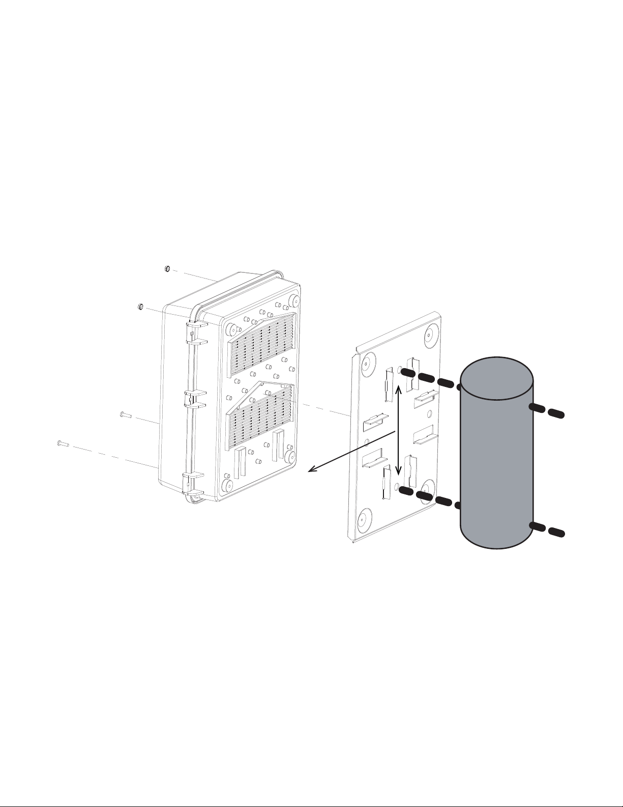
7.2.2 Mounting to a Wooden Pole (optional)
The Alpha Micro 100 can be pole mounted with the mounting bracket (Alpha Kit# 740-751-21), which allows you to
mount to a wooden pole.
Procedure:
To bolt the UPS to the pole you need the optional mounting bracket as well as two, ½" bolts (not provided) to fit the
pole.
1. Using the mounting bracket as a template, mark the positioning of the two holes on the pole.
2. Drill holes into the pole to fit the bolts.
3. Attach the bracket to the pole.
4. Secure the UPS enclosure to the mounting bracket with the two mounting screws and the two nuts provided
with the pole mount kit.
Figure 5 — Mounting to a wooden pole
9" distance
between holes
Table of contents
Other EnerSys UPS manuals


