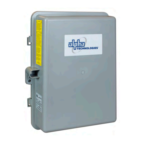
EnerSys Alpha FXM HP 650 Quick start guide

Alpha
FXM HP 650, 1100, 2000 UPS
Technical Guide: 0170022-J0
Effective: 11/2019


Alpha FXM-HP 650, 1100, 2000 UPS
Installation and Operation Manual
NOTE: Photographs contained in this manual are for illustrative purposes only. These photographs may
not match your installation.
NOTE: Operator is cautioned to review the drawings and illustrations contained in this manual before
proceeding. If there are questions regarding the safe operation of this powering system, contact Alpha
Technologies or your nearest Alpha representative.
NOTE: Alpha shall not be held liable for any damage or injury involving its enclosures, power supplies,
generators, batteries, or other hardware if used or operated in any manner or subject to any condition
inconsistent with its intended purpose, or if installed or operated in an unapproved manner, or
improp-erly maintained.
)RUWHFKQLFDOVXSSRUWFRQWDFW$OSKD7HFKQRORJLHV
&DQDGDDQG86$
,QWHUQDWLRQDO
Copyright
Copyright © 2019Alpha Technologies Ltd. All rights reserved. Alpha is a registered trademark of Alpha
Technologies.
No part of this documentation shall be reproduced, stored in a retrieval system, translated, transcribed,
or transmitted in any form or by any means manual, electric, electronic, electromechanical, chemical,
optical, or other-wise without prior explicit written permission from Alpha Technologies.
This document, the software it describes, and the information and know-how they contain constitute the
proprietary, confidential and valuable trade secret information of Alpha Technologies, and may not be
used for any unauthorized purpose, or disclosed to others without the prior written permission of Alpha
Technologies.
The material contained in this document is for information only and is subject to change without notice.
While reasonable efforts have been made in the preparation of this document to assure its accuracy,
Alpha Technologies assumes no liability resulting from errors or omissions in this document, or from the
use of the information contained herein. Alpha Technologies reserves the right to make changes in the
product design without reservation and without notification to its users.


i
TABLE OF CONTENTS
1 SAFETY . . . . . . . . . . . . . . . . . . . . . . . . . . . . . . . . . . . . . 1
Safety Wording . . . . . . . . . . . . . . . . . . . . . . . . . . . . . . . . . 1
General Warning and Cautions . . . . . . . . . . . . . . . . . . . . . . . . . 1
Electrical Safety . . . . . . . . . . . . . . . . . . . . . . . . . . . . . . . . . 1
Battery Safety . . . . . . . . . . . . . . . . . . . . . . . . . . . . . . . . . . 2
2 INTRODUCTION . . . . . . . . . . . . . . . . . . . . . . . . . . . . . . . . . . 3
Scope of the Manual . . . . . . . . . . . . . . . . . . . . . . . . . . . . . . 3
Product Overview . . . . . . . . . . . . . . . . . . . . . . . . . . . . . . . . 3
About Battery Backup Systems . . . . . . . . . . . . . . . . . . . . . . . 3
About the Alpha FXM HP . . . . . . . . . . . . . . . . . . . . . . . . . . 3
Peripherals . . . . . . . . . . . . . . . . . . . . . . . . . . . . . . . . . . 4
Alpha Cordex™ HP Digital Controller . . . . . . . . . . . . . . . . . . . . 4
3 FXM HP - SPECIFICATIONS . . . . . . . . . . . . . . . . . . . . . . . . . . . . 5
FXM HP - AVR Transition . . . . . . . . . . . . . . . . . . . . . . . . . . . . 8
4 FEATURES . . . . . . . . . . . . . . . . . . . . . . . . . . . . . . . . . . . . 11
Front Panel . . . . . . . . . . . . . . . . . . . . . . . . . . . . . . . . . . . 11
Feature Description . . . . . . . . . . . . . . . . . . . . . . . . . . . . . . . 12
Dry Contact Description . . . . . . . . . . . . . . . . . . . . . . . . . . . . . 13
5 INSPECTION . . . . . . . . . . . . . . . . . . . . . . . . . . . . . . . . . . . 17
Check for Damage . . . . . . . . . . . . . . . . . . . . . . . . . . . . . . . 17
Packing Materials . . . . . . . . . . . . . . . . . . . . . . . . . . . . . . . . 17
Returns for Service . . . . . . . . . . . . . . . . . . . . . . . . . . . . . . . 17
6 INSTALLATION . . . . . . . . . . . . . . . . . . . . . . . . . . . . . . . . . . 19
Installation . . . . . . . . . . . . . . . . . . . . . . . . . . . . . . . . . . . . 19
Tools Required . . . . . . . . . . . . . . . . . . . . . . . . . . . . . . . 19
Mounting the Alpha FXM HP . . . . . . . . . . . . . . . . . . . . . . . . . . 19
Rotating the Control Panel . . . . . . . . . . . . . . . . . . . . . . . . . . 22
Replacing the Fan . . . . . . . . . . . . . . . . . . . . . . . . . . . . . . 24
Wiring the External Batteries . . . . . . . . . . . . . . . . . . . . . . . . . . 25
Wiring the Alpha FXM HP . . . . . . . . . . . . . . . . . . . . . . . . . . . . 27
UATS and (UGTS) Option . . . . . . . . . . . . . . . . . . . . . . . . . . . . 27
7 OPERATING THE ALPHA FXM HP . . . . . . . . . . . . . . . . . . . . . . . . . 29
Switching the Alpha FXM HP On and Off . . . . . . . . . . . . . . . . . . . . 29
Switch Off Procedure . . . . . . . . . . . . . . . . . . . . . . . . . . . . 29
Switch On Procedure (LINE mode) . . . . . . . . . . . . . . . . . . . . . 29

ii
Switching the Alpha FXM HP from Line mode to Inverter mode . . . . . . 29
Switching the Alpha FXM HP from Inverter mode to Line mode . . . . . . 30
8 GETTING STARTED . . . . . . . . . . . . . . . . . . . . . . . . . . . . . . . . 31
Navigating the FXM HP User Interface . . . . . . . . . . . . . . . . . . . . . 31
Logging in to the Controller . . . . . . . . . . . . . . . . . . . . . . . . . 31
Controller Menu Map . . . . . . . . . . . . . . . . . . . . . . . . . . . . 32
Overview of the LCD Interface . . . . . . . . . . . . . . . . . . . . . . . . 34
Overview of the Web Interface . . . . . . . . . . . . . . . . . . . . . . . 47
Email Notification . . . . . . . . . . . . . . . . . . . . . . . . . . . . . . . . 56
Setting up SNMP Communication . . . . . . . . . . . . . . . . . . . . . . . . 59
Configuring IP Address to Receive Notifications . . . . . . . . . . . . . . 59
9 FXM HP SYSTEMS . . . . . . . . . . . . . . . . . . . . . . . . . . . . . . . . 61
Guidelines for Setting Up the FXM HP System . . . . . . . . . . . . . . . . . 61
The System Mode . . . . . . . . . . . . . . . . . . . . . . . . . . . . . . 61
FXM HP System Functions . . . . . . . . . . . . . . . . . . . . . . . . . . . 63
Modules, Inventory and System Functions . . . . . . . . . . . . . . . . . 63
Battery Charging . . . . . . . . . . . . . . . . . . . . . . . . . . . . . . . 63
Battery Temperature Compensation . . . . . . . . . . . . . . . . . . . . . 64
Battery Test . . . . . . . . . . . . . . . . . . . . . . . . . . . . . . . . . 65
Battery Runtime and Health Estimation . . . . . . . . . . . . . . . . . . . 66
AC Output . . . . . . . . . . . . . . . . . . . . . . . . . . . . . . . . . . 67
Inverter Control . . . . . . . . . . . . . . . . . . . . . . . . . . . . . . . 67
Load Shedding Relays . . . . . . . . . . . . . . . . . . . . . . . . . . . . 68
External Fan . . . . . . . . . . . . . . . . . . . . . . . . . . . . . . . . . 69
Keep Alive . . . . . . . . . . . . . . . . . . . . . . . . . . . . . . . . . . 69
Creating a FXM HP System Manually . . . . . . . . . . . . . . . . . . . . . . 71
Quick Reference for Configuring a FXM HP System . . . . . . . . . . . . 71
FXM HP - Default Values . . . . . . . . . . . . . . . . . . . . . . . . . . 73
Creating a FXM HP System . . . . . . . . . . . . . . . . . . . . . . . . . 76
Configure the Battery Parameters . . . . . . . . . . . . . . . . . . . . . . 81
Configure the Battery Temperature Sensors . . . . . . . . . . . . . . . . 81
Configure the Charging System Function . . . . . . . . . . . . . . . . . . 82
Configure the Elevated Absorption Charging System . . . . . . . . . . . . 83
Configure the Temperature Compensation System Function . . . . . . . . 83
Running Battery Tests . . . . . . . . . . . . . . . . . . . . . . . . . . . . 83
Configure Battery Runtime and Health Estimation . . . . . . . . . . . . . 85
Configure AC Shutdown . . . . . . . . . . . . . . . . . . . . . . . . . . . 85
Configure External Fan . . . . . . . . . . . . . . . . . . . . . . . . . . . 86
Configure Keep Alive . . . . . . . . . . . . . . . . . . . . . . . . . . . . 87
Configure Soft Shutdown . . . . . . . . . . . . . . . . . . . . . . . . . . 87
Configure SNMP UPS Management Information Base . . . . . . . . . . . 87
Configure Relays . . . . . . . . . . . . . . . . . . . . . . . . . . . . . . 87
Configure Power Outage Alarm . . . . . . . . . . . . . . . . . . . . . . . 89

iii
10 MAINTAINING THE CONTROLLER . . . . . . . . . . . . . . . . . . . . . . . . . 91
Ethernet Communications . . . . . . . . . . . . . . . . . . . . . . . . . . . . 91
Connecting via the Web . . . . . . . . . . . . . . . . . . . . . . . . . . . 92
Working with Alarms . . . . . . . . . . . . . . . . . . . . . . . . . . . . . . 92
Active Alarms . . . . . . . . . . . . . . . . . . . . . . . . . . . . . . . . 92
Alarm Cut-off . . . . . . . . . . . . . . . . . . . . . . . . . . . . . . . . . 93
Alarm Activation Delay at Startup . . . . . . . . . . . . . . . . . . . . . . 93
Alarm Summary Relays . . . . . . . . . . . . . . . . . . . . . . . . . . . 93
Creating User Alarms . . . . . . . . . . . . . . . . . . . . . . . . . . . . 95
Controller Maintenance . . . . . . . . . . . . . . . . . . . . . . . . . . . . . 96
Resetting the Controller . . . . . . . . . . . . . . . . . . . . . . . . . . . 96
Resetting via the LCD . . . . . . . . . . . . . . . . . . . . . . . . . . . . 97
Changing the Time and Date . . . . . . . . . . . . . . . . . . . . . . . . 97
Changing the Default Login Language . . . . . . . . . . . . . . . . . . . 98
Changing User Interface Strings . . . . . . . . . . . . . . . . . . . . . . . 99
Changing the Web Session Language . . . . . . . . . . . . . . . . . . 100
Changing the System Status Bar . . . . . . . . . . . . . . . . . . . . . 101
Changing the Dashboard Values . . . . . . . . . . . . . . . . . . . . . 102
Data Sharing . . . . . . . . . . . . . . . . . . . . . . . . . . . . . . . . 102
Replacing the Controller Battery . . . . . . . . . . . . . . . . . . . . . . 104
Working with Logs . . . . . . . . . . . . . . . . . . . . . . . . . . . . . . . 105
Event and Alert Logs . . . . . . . . . . . . . . . . . . . . . . . . . . . 105
Battery Log . . . . . . . . . . . . . . . . . . . . . . . . . . . . . . . . 106
Power Outage Log . . . . . . . . . . . . . . . . . . . . . . . . . . . . . 107
Datalogs . . . . . . . . . . . . . . . . . . . . . . . . . . . . . . . . . . 107
Performance Logs . . . . . . . . . . . . . . . . . . . . . . . . . . . . . 111
File Maintenance . . . . . . . . . . . . . . . . . . . . . . . . . . . . . . . 111
File Preferences . . . . . . . . . . . . . . . . . . . . . . . . . . . . . . 112
File Maintenance via the LCD . . . . . . . . . . . . . . . . . . . . . . . 112
Upgrading the Controller Software . . . . . . . . . . . . . . . . . . . . 114
Exporting Configuration . . . . . . . . . . . . . . . . . . . . . . . . . . 115
Importing Configuration . . . . . . . . . . . . . . . . . . . . . . . . . . 116
Exporting Diagnostic Information . . . . . . . . . . . . . . . . . . . . . 118
Exporting Inventory . . . . . . . . . . . . . . . . . . . . . . . . . . . . 118
User Account Maintenance . . . . . . . . . . . . . . . . . . . . . . . . . . 119
Setting Up Users and Permissions . . . . . . . . . . . . . . . . . . . . 119
Editing User Permissions . . . . . . . . . . . . . . . . . . . . . . . . . 119
Enabling New Users . . . . . . . . . . . . . . . . . . . . . . . . . . . . 120
Disabling Users . . . . . . . . . . . . . . . . . . . . . . . . . . . . . . 122
Changing the Default Password - LCD . . . . . . . . . . . . . . . . . . 123
Changing the Default Password - Web . . . . . . . . . . . . . . . . . . 124
Remote Configuration Lockout . . . . . . . . . . . . . . . . . . . . . . 125
Module Firmware Upgrades . . . . . . . . . . . . . . . . . . . . . . . . . . 125
Module Firmware Upgrade . . . . . . . . . . . . . . . . . . . . . . . . 125
Uploading a Firmware File . . . . . . . . . . . . . . . . . . . . . . . . . 126
Selecting the File to Upgrade . . . . . . . . . . . . . . . . . . . . . . . 128

iv
Upgrading the Module . . . . . . . . . . . . . . . . . . . . . . . . . . . 129
11 APPENDIX A - TRIGGERS . . . . . . . . . . . . . . . . . . . . . . . . . . . . 131
12 WARRANTY AND SERVICE INFORMATION . . . . . . . . . . . . . . . . . . . . 133
Technical Support . . . . . . . . . . . . . . . . . . . . . . . . . . . . . . . 133
Warranty Statement . . . . . . . . . . . . . . . . . . . . . . . . . . . . . . 133
Product Warranty . . . . . . . . . . . . . . . . . . . . . . . . . . . . . . . 133
Battery Warranty . . . . . . . . . . . . . . . . . . . . . . . . . . . . . . . 133
Warranty Claims . . . . . . . . . . . . . . . . . . . . . . . . . . . . . . . . 133
Service Information . . . . . . . . . . . . . . . . . . . . . . . . . . . . . . 133
13 CERTIFICATION . . . . . . . . . . . . . . . . . . . . . . . . . . . . . . . . . 135

v
LIST OF FIGURES
Figure 1: FXM HP 650 . . . . . . . . . . . . . . . . . . . . . . . . . . . . . . . . . 11
Figure 2: FXM HP 1100/2000 . . . . . . . . . . . . . . . . . . . . . . . . . . . . .11
Figure 3: Dry Contact Overview . . . . . . . . . . . . . . . . . . . . . . . . . . . .13
Figure 4: User Input Layout. . . . . . . . . . . . . . . . . . . . . . . . . . . . . . .14
Figure 5: Contact Layout (De-energized Shown, Factory Default for C6) . . . . . . .14
Figure 6: ATS Layout . . . . . . . . . . . . . . . . . . . . . . . . . . . . . . . . . .15
Figure 7: Packing Materials and Environmental Codes . . . . . . . . . . . . . . . .17
Figure 8: Menu Structure . . . . . . . . . . . . . . . . . . . . . . . . . . . . . . . .33
Figure 9: FXM HP Controller Dashboard . . . . . . . . . . . . . . . . . . . . . . . .34
Figure 10: Maintenance Page . . . . . . . . . . . . . . . . . . . . . . . . . . . . . .35
Figure 11: System Maintenance Page . . . . . . . . . . . . . . . . . . . . . . . . .35
Figure 12: LCD Menus . . . . . . . . . . . . . . . . . . . . . . . . . . . . . . . . .36
Figure 13: Controller Status . . . . . . . . . . . . . . . . . . . . . . . . . . . . . . .37
Figure 14: Time and Date . . . . . . . . . . . . . . . . . . . . . . . . . . . . . . . .37
Figure 15: Timezone . . . . . . . . . . . . . . . . . . . . . . . . . . . . . . . . . . .38
Figure 16: Network Time Server . . . . . . . . . . . . . . . . . . . . . . . . . . . . .38
Figure 17: Synchronize Time . . . . . . . . . . . . . . . . . . . . . . . . . . . . . .39
Figure 18: System Shortcuts . . . . . . . . . . . . . . . . . . . . . . . . . . . . . .39
Figure 19: Status . . . . . . . . . . . . . . . . . . . . . . . . . . . . . . . . . . . .40
Figure 20: AC Input . . . . . . . . . . . . . . . . . . . . . . . . . . . . . . . . . . .40
Figure 21: AC Output . . . . . . . . . . . . . . . . . . . . . . . . . . . . . . . . . .40
Figure 22: Battery . . . . . . . . . . . . . . . . . . . . . . . . . . . . . . . . . . . .41
Figure 23: Battery Test . . . . . . . . . . . . . . . . . . . . . . . . . . . . . . . . .41
Figure 24: Inverter Control . . . . . . . . . . . . . . . . . . . . . . . . . . . . . . . .42
Figure 25: AC Shutdown . . . . . . . . . . . . . . . . . . . . . . . . . . . . . . . .42
Figure 26: Counters . . . . . . . . . . . . . . . . . . . . . . . . . . . . . . . . . . .43
Figure 27: Keep Alive Status . . . . . . . . . . . . . . . . . . . . . . . . . . . . . . 43
Figure 28: External Fan . . . . . . . . . . . . . . . . . . . . . . . . . . . . . . . . .43
Figure 29: User Inputs Status . . . . . . . . . . . . . . . . . . . . . . . . . . . . . .44
Figure 30: User Inputs Configuration . . . . . . . . . . . . . . . . . . . . . . . . . .44
Figure 31: User Alarms . . . . . . . . . . . . . . . . . . . . . . . . . . . . . . . . .45
Figure 32: Relays . . . . . . . . . . . . . . . . . . . . . . . . . . . . . . . . . . . . 45
Figure 33: Relays Status . . . . . . . . . . . . . . . . . . . . . . . . . . . . . . . . 45
Figure 34: Relays Configuration . . . . . . . . . . . . . . . . . . . . . . . . . . . . .46
Figure 35: Load Shedding Relays . . . . . . . . . . . . . . . . . . . . . . . . . . . .46
Figure 36: Events Logs. . . . . . . . . . . . . . . . . . . . . . . . . . . . . . . . . .47

vi
Figure 37: Dashboard Overview on Web Interface . . . . . . . . . . . . . . . . . . .48
Figure 38: Main Dashboard Tables . . . . . . . . . . . . . . . . . . . . . . . . . . .49
Figure 39: Table Icons . . . . . . . . . . . . . . . . . . . . . . . . . . . . . . . . . .50
Figure 40: Web Interface Table Features . . . . . . . . . . . . . . . . . . . . . . . .51
Figure 41: Controller Menu. . . . . . . . . . . . . . . . . . . . . . . . . . . . . . . .51
Figure 42: System Wizards . . . . . . . . . . . . . . . . . . . . . . . . . . . . . . .52
Figure 43: Controller with No System Configured . . . . . . . . . . . . . . . . . . . .53
Figure 44: Systems Data Tiles . . . . . . . . . . . . . . . . . . . . . . . . . . . . . .53
Figure 45: System Menu . . . . . . . . . . . . . . . . . . . . . . . . . . . . . . . .53
Figure 46: Modules Menu . . . . . . . . . . . . . . . . . . . . . . . . . . . . . . . .55
Figure 47: Alarms Menu . . . . . . . . . . . . . . . . . . . . . . . . . . . . . . . . .55
Figure 48: Logs Menu . . . . . . . . . . . . . . . . . . . . . . . . . . . . . . . . . .56
Figure 49: Default Ports: SMTP Client and Server. . . . . . . . . . . . . . . . . . . .56
Figure 50: Default Ports: SNMP Manager and Agent . . . . . . . . . . . . . . . . . .59
Figure 51: SNMP Destination Page: . . . . . . . . . . . . . . . . . . . . . . . . . . .60
Figure 52: Destination 1 More Information Page: . . . . . . . . . . . . . . . . . . . .60
Figure 53: System Mode . . . . . . . . . . . . . . . . . . . . . . . . . . . . . . . . .62
Figure 54: Three-Stage Charging Cycle . . . . . . . . . . . . . . . . . . . . . . . . .64
Figure 55: Temperature Compensation Voltage Graph . . . . . . . . . . . . . . . . .65
Figure 56: Quick Reference for Configuring a FXM System . . . . . . . . . . . . . . .72
Figure 57: Events and Alerts Log . . . . . . . . . . . . . . . . . . . . . . . . . . . 105
Figure 58: Battery Log on the LCD. . . . . . . . . . . . . . . . . . . . . . . . . . . 106
Figure 59: Battery Log on the Web. . . . . . . . . . . . . . . . . . . . . . . . . . . 107
Figure 60: Battery Log in Excel . . . . . . . . . . . . . . . . . . . . . . . . . . . . 107
Figure 61: Datalogs Table . . . . . . . . . . . . . . . . . . . . . . . . . . . . . . . 107
Figure 62: Datalog Window: Status, Signals, Configuration and Preview Chart . . . . 108
Figure 63: CPU Memory in Use Performance Log . . . . . . . . . . . . . . . . . . . 111
Figure 64: Module Upgrade Page - web . . . . . . . . . . . . . . . . . . . . . . . . 126
Figure 65: Module Upgrade - LCD . . . . . . . . . . . . . . . . . . . . . . . . . . . 126
Figure 66: Firmware Files Table . . . . . . . . . . . . . . . . . . . . . . . . . . . . 127
Figure 67: Upload File Dialog . . . . . . . . . . . . . . . . . . . . . . . . . . . . . 127
Figure 68: Ready to Start Upgrade. . . . . . . . . . . . . . . . . . . . . . . . . . . 128
Figure 69: Upgrade in Progress . . . . . . . . . . . . . . . . . . . . . . . . . . . . 129
Figure 70: Upgrade Succeeded . . . . . . . . . . . . . . . . . . . . . . . . . . . . 130

vii
LIST OF TABLES
Table 1: Specifications: FXM HP 650, 1100, 2000. . . . . . . . . . . . . . . . . . . 5
Table 2: AVR Transition: FXM HP 2000 - 120V . . . . . . . . . . . . . . . . . . . . 8
Table 3: AVR Transition: FXM HP 650, 1100 - 120V . . . . . . . . . . . . . . . . . 9
Table 4: AVR Transition: FXM HP 650, 1100, 2000 - 230V . . . . . . . . . . . . . . 9
Table 5: Feature Description. . . . . . . . . . . . . . . . . . . . . . . . . . . . . .12
Table 6: C1 to C5 Dry Contacts . . . . . . . . . . . . . . . . . . . . . . . . . . . .13
Table 7: C7 to C8 Optically Isolated User Inputs . . . . . . . . . . . . . . . . . . .14
Table 8: FXM HP Part Numbers . . . . . . . . . . . . . . . . . . . . . . . . . . . .19
Table 9: Email Notification Features . . . . . . . . . . . . . . . . . . . . . . . . . .57
Table 10: Email Configuration. . . . . . . . . . . . . . . . . . . . . . . . . . . . . .58
Table 11: FXM HP Operating Mode . . . . . . . . . . . . . . . . . . . . . . . . . . .62
Table 12: Inverter Control Configuration Table . . . . . . . . . . . . . . . . . . . . .68
Table 13: The Load Shedding Relays Configuration Table . . . . . . . . . . . . . . .68
Table 14: External Fan Configuration Table. . . . . . . . . . . . . . . . . . . . . . .69
Table 15: Keep Alive Configuration Table. . . . . . . . . . . . . . . . . . . . . . . .70
Table 16: FXM HP - Default Values . . . . . . . . . . . . . . . . . . . . . . . . . . .73

viii

0170022-J0 Rev A Page 1
1 Safety
SAVE THESE INSTRUCTIONS: This manual contains important safety instructions that must be
followed during the installation, servicing, and maintenance of the product. Keep it in a safe place.
Review the drawings and illustrations contained in this manual before proceeding. If there are any ques-
tions regarding the safe installation or operation of this product, contact Alpha Technologies or the
nearest Alpha representative.
1.1 Safety Wording
To reduce the risk of injury or death, and to ensure the continued safe operation of this product, the
following labels have been placed throughout this manual. Where these words appear, use extra care
and attention.
ATTENTION: The use of attention indicates specific regulatory/code requirements that may affect the
placement of equipment and /or installation procedures.
NOTE: Notes provide additional information to help complete a specific task or procedure.
CAUTION: Cautions indicate safety information intended to PREVENT DAMAGE to material or equip-
ment.
WARNING: Warnings present safety information to PREVENT INJURY OR DEATH to personnel.
NOTE: HOT! The use of Hot presents safety information to PREVENT BURNS to the technician or user.
1.2 General Warning and Cautions
WARNING: You must read and understand the following warnings before installing the system and its
components. Failure to do so could result in personal injury or death.
• Read and follow all instructions included in this manual.
• Only trained personnel are qualified to install or replace this equipment and its components.
• Use proper lifting techniques whenever handling equipment, parts, or batteries.
1.3 Electrical Safety
WARNING: Hazardous voltages are present at the input of power systems. The DC output from some
UPS devices and batteries can have high voltage and high short-circuit current capacity that may cause
severe burns and electrical arcing.
Before working with any live battery or power system, follow these precautions:
• Remove all metallic jewelry, such as watches, rings, metal rimmed glasses, or necklaces.
• Wear safety glasses with side shields at all times during the installation.
• Use OSHA approved insulated hand tools. Do not rest tools on top of batteries.
WARNING: Lethal voltages are present within the system. Always assume that an electrical connection
or conductor is energized. Check the circuit with a voltmeter with respect to the grounded portion of the
enclosure (both AC and DC) before performing any installation or removal procedure.
• Do not work alone under hazardous conditions.

0170022-J0 Rev A Page 2
• A licensed electrician is required to install permanently wired equipment. Input voltages can range
up to 240Vac. Ensure that the utility power is disconnected and locked out before performing any
installation or removal procedure.
• Ensure that no liquids or wet clothes come into contact with internal components.
• Hazardous electrically live parts inside this unit are energized from the batteries even when the
AC input power is disconnected.
• Always assume electrical connections or conductors are live. Turn off all circuit breakers and
double-check with a voltmeter before performing installation or maintenance.
• Place a warning label on the utility panel to warn emergency personnel that a reserve battery
source is present which will power the loads in a power outage condition or if the AC disconnect
breaker is turned off.
• At high ambient temperature conditions, the internal temperature can be hot so use caution when
touching the equipment.
1.4 Battery Safety
• Never transport an enclosure with batteries installed. Batteries must ONLY be installed after the
enclosure has been securely set in place at its permanent installation location. Transporting the
unit with batteries installed may cause a short circuit, fire, explosion, and/or damage to the battery
pack, enclosure and installed equipment.
• Servicing and connection of batteries must be performed by, or under the direct supervision of,
personnel knowledgeable of batteries and the required safety precautions.
• Batteries contain or emit chemicals known to cause cancer and birth defects or other reproductive
harm. Battery post terminals and related accessories contain lead and lead compounds. Wash
your hands after handling batteries.
WARNING: Follow battery manufacturer’s safety recommendations when working around battery
systems. Do not smoke or introduce an open flame when batteries (especially vented batteries) are
charging. When charging, batteries vent hydrogen gas, which can explode.
• Batteries are hazardous to the environment and should be disposed at a recycling facility. Consult
the battery manufacturer for recommended local authorized recyclers.

0170022-J0 Rev A Page 3
2 Introduction
2.1 Scope of the Manual
This manual covers the features, options, installation and startup of the Alpha FXM HP family of UPS
(uninterruptible power supply) devices. Images contained in this document are for illustrative purposes
only and may not exactly match your installation. This manual supports the following Alpha FXM HP
models:
• FXM HP 650-24Vdc – with a 24Vdc battery string voltage (120Vac and 230Vac)
• FXM HP 650-48Vdc – with a 48Vdc battery string voltage (120Vac)
• FXM HP 1100-48Vdc – with a 48Vdc battery string voltage (120Vac and 230Vac)
• FXM HP 2000-48Vdc – with a 48Vdc battery string voltage (120Vac and 230Vac)
2.2 Product Overview
2.2.1 About Battery Backup Systems
Battery Backup Systems (BBS) / Uninterruptible Power Supply (UPS) are the first line of defense to
keep critical loads backed up during power outages as well as increasing equipment reliability by
protecting them against power disturbances. Battery Backup Systems need to be rugged, reliable, and
informative in the data they provide. Typical applications include traffic infrastructure, ITS equipment,
security devices, parking gates, ticket dispensers, VMS signs and AC Small Cell power backup. Some
of the benefits of BBS are:
• Providing continual power to your operating system in the event of a power outage, sag or brown
out, until regular utility power is restored.
• Conditioning and regulating the quality of the commercial power supply to your critical load.
• Keeping your traffic intersections and data flowing to prevent or minimize severe accidents and
downtime.
• Reducing operating expenses by eliminating false service call-outs and expensive truck roll-outs.
2.2.2 About the Alpha FXM HP
The Alpha FXM HP is a new line of rugged UPS power modules for the most demanding environments
where clean backup power is needed. Alpha FXM HP units ensure equipment in critical applications
remains safe and protected from power disturbances and outages. Some of the key features of the FXM
HP are below:
• Full color LCD touchscreen display
• Front panel LEDs for alarms, progress and status indication
• Dual Ethernet ports for remote or local communication
• USB-A port for upgrades or file management via a standard USB flash drive
• USB-Mini B port for soft shutdown using MegaTec protocol compliant client
• Independent CAN bus ports for communication with the Alpha Cordex™ family of products
• User programmable dry contacts for control and monitoring of key functions

0170022-J0 Rev A Page 4
• Customizable user configurations that can be exported and imported to other FXM HP units
2.2.3 Peripherals
The FXM HP can be used together with an external analog and digital input and output peripheral to
monitor electrical signals (temperature, voltage, current) and generate electrical signals through relays.
The most commonly used ADIO (Analog Digital Input Output) peripheral is the L-ADIO (Low Voltage-
Analog Digital Input Output) for low voltage systems. Features include:
• Eight digital inputs
• Four voltage sensors
• Four temperature sensors
• Four current sensors
• 12 Form C relay outputs
2.2.4 Alpha Cordex™ HP Digital Controller
The FXM HP uses the advanced Alpha Cordex™ HP digital controller for monitoring and control. It
offers a common user interface across all Alpha products – FXM HP, DC Power Plants, Inverter
Systems and Line Powering. This provides seamless integration of multiple systems allowing compre-
hensive management and common interface using a single IP connection.
NOTE: While referring to monitoring and control FXM HP or Controller will be used interchangeably in
this manual.

0170022-J0 Rev A Page 5
3 FXM HP - Specifications
Table 1: Specifications: FXM HP 650, 1100, 2000 (Sheet 1 of 4)
FXM HP
650-24
120Vac
FXM HP
650-24
230Vac
FXM HP
650-48
120Vac
FXM HP
1100
120Vac
FXM HP
1100
230Vac
FXM HP
2000
120Vac
FXM HP
2000
230Vac
Electrical Input
Voltage Range
in Line Mode
(Vac) +/-2V
85-171 153-322 85-171 85-171 153-322 85-150 153-322
Nominal
Frequency
(Hz)
50Hz or 60Hz (Autodetect Frequency is the default configuration, can also be
manually configured.)
Frequency
Tolerance in
Line Mode
+/- 5%
Maximum Input
Current (A)1
8 4.4 10.5 15 8 20 12
Input Breaker
Rating (A)
10 5.5 15 20 10 25 15E
Electrical Output
Output Voltage
Setting (V)
120 210, 220,
230, 240
120 120 210, 220,
230, 240
120 210, 220,
230, 240
% Regulation
(Line Mode)
+/-10%
% Regulation
(Inverter Mode)
+/-2%
Rated Power
(W/VA)
650 650 650 1100 1100 2000 2000
Frequency
(Hz)
Same as Input Frequency
Battery
Battery String
Voltage (V)
24 24 48 48 48 48 48

0170022-J0 Rev A Page 6
Maximum
Charging
Current (A)
10 10 10 15 15 15 15
Battery
Breaker Rating
(A)
80 80 50 50 50 80 80
Performance
Line Mode
Efficiency2
>98% >98% >97.5% >98% >97% >97.5% >97%
Inverter Mode
Efficiency3
>75% >75% >85% >85% >85% >85% >85%
Typical
Transfer Time
5ms
Voltage THD
(%)
<3% <3% <3% <3% <3.5% <3% <5%
Waveform Pure Sine Wave
Load Crest
Factor
3:1 (load dependent)
Mechanical
Dimensions H
x W x D mm
(in)
89 x 432 x 229(3.47 x 17 x 9) 133 x 394 x 222 (5.22 x 15.5 x 8.75)
Weight without
batteries kg (lb)
11.3 (25) 14 (31) 18 (40)
Mounting Shelf, rack or wall; horizontal or vertical mount
Cooling Forced air (fan cooled) with optional external fan cooling for enclosure
Display Full graphic LCD, 480x272 pixels, Resistive touch screen
Table 1: Specifications: FXM HP 650, 1100, 2000 (Continued) (Sheet 2 of 4)
FXM HP
650-24
120Vac
FXM HP
650-24
230Vac
FXM HP
650-48
120Vac
FXM HP
1100
120Vac
FXM HP
1100
230Vac
FXM HP
2000
120Vac
FXM HP
2000
230Vac

0170022-J0 Rev A Page 7
Communicat-
ion Ports
2 x RJ45: Ethernet
1 x USB A
1 x USB Mini B
1 x RJ12: CAN
1 x RJ11: Battery Temperature Compensation
Indicators Solid Green: Line Mode
Flashing Green: Inverter mode
Yellow: Minor alarms
Red: Major/Critical alarms
Environmental
Full Load
Operating
Temp Range4
-40 to
55°C
@60Hz
-40 to
50°C
@50Hz
-40 to
40°C
@210V
-40 to
50°C
@220V
-40 to
55°C
@230,
240V
-40 to
55°C
-40 to
50°C
-40 to
55°C
@220,
230,
240V
-40 to
45°C
@210V
-40 to
50°C
-40 to
55°C
Humidity Up to 95% (non condensing)
Altitude, m (ft)53700 (12,000)
Audible Noise645dBa @ 1 meter
BTU/Hr
(Inverter Mode)
700 845 375 640 675 1235 1185
Connections
AC input and
output
connectors
Terminal block, Weco p/n 324-HDS/03 or equivalent (max 10 AWG)
Dry contacts C1 to C5 Programmable NO/NC (240Vac, 1A max)
C6: 24VDC @ 500mA, 3 user inputs, ATS: 24VDC/10mA
C6: 48VDC @ 500mA, 3 user inputs, ATS: 48VDC/10mA
Table 1: Specifications: FXM HP 650, 1100, 2000 (Continued) (Sheet 3 of 4)
FXM HP
650-24
120Vac
FXM HP
650-24
230Vac
FXM HP
650-48
120Vac
FXM HP
1100
120Vac
FXM HP
1100
230Vac
FXM HP
2000
120Vac
FXM HP
2000
230Vac

0170022-J0 Rev A Page 8
3.1 FXM HP - AVR Transition
Compliance
Safety UL 1778, CAN/CSA-C22.2 No. 107.3-14, EN 62040-1
EMC FCC CFR47 Part 15, Class A, CSPR22, EN62040-2, EN55022 Level A, C62.41
1. Measured at nominal input voltage and load.
2. Measured at nominal AC Input and full load.
3. Measured at nominal DC Input and full load.
4. Derates 1.4% per °C past this range until a maximum of 74°C.
5. Derates 2°C per 300m (1000ft) above 1400m (4500ft).
6. Measured at 25°C ambient temperature.
Table 1: Specifications: FXM HP 650, 1100, 2000 (Continued) (Sheet 4 of 4)
FXM HP
650-24
120Vac
FXM HP
650-24
230Vac
FXM HP
650-48
120Vac
FXM HP
1100
120Vac
FXM HP
1100
230Vac
FXM HP
2000
120Vac
FXM HP
2000
230Vac
Table 2: AVR Transition: FXM HP 2000 - 120V
AVR Transition FXM HP 2000-120 120V (Vac)
Inverter to Boost 2 89.4
Boost 2 to Boost 1 99.5
Boost 1 to Line 112.7
Line to Buck 1 129.6
Buck 1 to Inverter 148.4
Inverter to Buck 1 141.5
Buck 1 to Line 126.4
Line to Boost 1 110.4
Boost 1 to Boost 2 96
Boost 2 to Inverter 84.8
Vin (Vac) all thresholds are within +/-0.5V of the specified values
This manual suits for next models
2
Table of contents
Other EnerSys UPS manuals
