Orvaldi V10KRT User manual

ORVALDI V10KRT/V15KRT/V20KRT 3/3 (3/1)
Online UPS
Uninterruptible Power Supply System
Version: 1.1
User Manual

Please comply with all warnings and operating
instructions in this manual. This equipment
should only be installed, serviced, and
maintained by qualified personnel. Do not
operate this unit before reading through all
safety information and operating instructions
carefully.
Disclaimer
We assumes no responsibility or liability for loss or damages, whether direct, indirect,
consequential or incidental, which might arise out of the use of such information. The use of
any such information will be entirely at the user’s risk. Information in this manual is subject to
change without notice. We make no commitment to update or keep current the information in
this manual. If you find information in this manual that is incorrect, misleading, or incomplete,
we would appreciate your comments and suggestions.

Table of Contents
1. SAFETY AND EMC INSTRUCTIONS ................................................................................................. 1
1-1. TRANSPORTATION AND STORAGE ...............................................................................................................1
1-2. PREPARATION.......................................................................................................................................1
1-3. INSTALLATION ......................................................................................................................................1
1-4. CONNECTION WARNINGS ...............................................................................................................2
1-5. OPERATION .........................................................................................................................................3
1-6. STANDARDS .........................................................................................................................................3
2. INSTALLATION AND OPERATION .................................................................................................. 4
2-1. UNPACKING AND INSPECTION ...................................................................................................................4
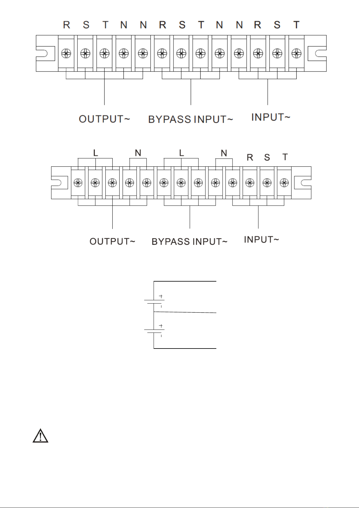
2-2. WIRING TERMINAL VIEW ........................................................................................................................5
2-3. SINGLE UPS INSTALLATION .....................................................................................................................6
2-4. UPS INSTALLATION FOR PARALLEL SYSTEM..................................................................................................8
2-5. SOFTWARE INSTALLATION .......................................................................................................................9
3. OPERATIONS................................................................................................................................ 10
3-1. BUTTON OPERATION ............................................................................................................................10
3-2. SCREEN DESCRIPTION ..........................................................................................................................10
3-3. AUDIBLE ALARM..................................................................................................................................39
3-4. SINGLE UPS OPERATION ......................................................................................................................39
3-5. PARALLEL OPERATION ..........................................................................................................................44
3-6. FAULT CODE ......................................................................................................................................46
3-7.WARNING CODE ..................................................................................................................................47
4. TROUBLE SHOOTING ................................................................................................................... 48
5. STORAGE AND MAINTENANCE..................................................................................................... 49
5-1. STORAGE ..........................................................................................................................................49
5-2. MAINTENANCE....................................................................................................................................49
6. SPECIFICATIONS ......................................................................................................................... 50

1
1. Safety and EMC instructions
All safety instructions in this document must be read, understood and followed.
1-1. Transportation and Storage
Please transport the UPS system only in the original packaging to protect against shock and
damage.
The UPS must be stored in the room where the temperature is well regulated. Ambient
temperature should not exceed 40°C.
1-2. Preparation
Condensation may form if the UPS system is moved immediately from cold to warm environment.
The UPS system must be absolutely dry before being installed. Please allow at least two hours for
the UPS system to acclimate the environment.
Do not install the UPS system near water or in moist environments.
Do not install the UPS system where it would be exposed to direct sunlight or nearby heat source.
Do not block ventilation holes on the UPS housing.
1-3. Installation
Do not connect appliances or devices which would overload the UPS (e.g. big motor-type
equipment)) to the UPS output terminal.
Place cables in such a way that no one can step on or trip over them.
Do not block air vents on the housing of the UPS. Ensure proper unit spacing of ventilation.
UPS came equipped with grounding terminal, in the final installation phase, connect grounding/
earthing wire to the external UPS battery cabinets or appropriate grounding terminals.
The UPS can be installed only by qualified maintenance personnel.
An appropriate disconnect device such as short-circuit backup protection should be incorporated
during installation.
An integral emergency shutoff switch which prevents additional load from the UPS in any mode
of operation should be implemented during the installation.
Secure the grounding/earthing wire before connecting to any live wire terminal.
Installation and Wiring must be in accordance with the local electrical laws and regulations.

2
1-4. Connection Warnings
•There is no standard backfeed protection inside of the UPS. However, there are relays on the Input to
cut off line voltage and while the neutral is still connect to UPS.
Main
Input
Input Rly
UPS
L1
L2
L3
N
Main
Input
Input Rly
UPS
L1
L2
L3
N
Bypass
Input
Input Rly
L1
L2
L3
N
Input relay diagram Input relay diagram for dual-input model
•This UPS should be connected with TN grounding/earthing system.
•The power input for this unit must be three-phase rated in accordance with the equipment nameplate. It
also must be suitably grounded.
•Use of this equipment in medical instrument of any life-sustaining equipment where failure of this
equipment can reasonably be expected to cause the failure of the life-sustaining equipment or to
significantly affect its safety or effectiveness is not recommended. Do not use this equipment in the
presence of a flammable mixture with air, oxygen or nitrous oxide.
•Connect grounding terminal of UPS to a grounding electrode conductor.
•In accordance with safety standard EN-IEC 62040-1, installation has to be provided with a《Backfeed
Protection》system, as for example a contactor, which will prevent the appearance of voltage or
dangerous energy in the input mains during a mains fault (respect the wiring diagram of «Backfeed
Protection» depending if the equipment is with signal or three phase input).
There can be no derivation in the line that goes from the «Backfeed Protection» to the UPS, as
the standard safety would be infringed.
•Warning labels should be placed on all primary power switches installed in places away from the unit to
alert the electrical maintenance personnel of the presence of a UPS in the circuit. The label will bear the
following or an equivalent text:
Before working on this circuit
-Isolate Uninterruptible Power Supply (UPS)
-Then check for Hazardous Voltage between all terminals including the protected
earth
Risk of Voltage Backfeed
WARNING
HIGH LEAKAGE CURRENT
EARTH CONNECTION ESSENTIAL
BEFORE CONNECTING SUPPLY

3
1-5. Operation
Do not disconnect the grounding/earthing conductor cable on the UPS or the building wiring
terminals under any circumstance.
The UPS system features its own, internal current source (batteries). The UPS output sockets or
output terminal blocks may be electrically live even if the UPS system is not connected to the building
mains/live wires. (only for standard models)
In order to fully disconnect the UPS system, first press the “OFF” button and then disconnect the
mains/live wires.
Ensure that no liquid or other foreign objects can enter into the UPS system.
The UPS can be operated by any individuals with no previous experience.
1-6. Standards
* Safety
IEC/EN 62040-1
* EMI
Conducted Emission................................ :IEC/EN 62040-2
Category C3
Radiated Emission................................... :IEC/EN 62040-2
Category C3
*EMS
ESD........................................................ :IEC/EN 61000-4-2 CD Level 2
AD Level 3
RS.......................................................... :IEC/EN 61000-4-3
Level 3
EFT......................................................... :IEC/EN 61000-4-4
Level 3
SURGE.................................................... :IEC/EN 61000-4-5
Level 3
CS.......................................................... :IEC/EN 61000-4-6
Level 3
Power-frequency Magnetic field................ :IEC/EN 61000-4-8
Level 4
Low Frequency Signals............................. :IEC/EN 61000-2-2 10V
Warning:
This is a product for commercial and industrial application in the
second environment-
installation restrictions or additional measures may be
needed to prevent disturbances.

4
2. Installation and Operation
We also offer optional parallel function for both models upon request. The UPS with parallel function is called
the “Parallel model”. We have detail installation and operation procedure of the Parallel Model in the
following chapter.
2-1. Unpacking and Inspection
Unpack the package and check the package contents. The shipping package should contain:
● One UPS
●One user manual
● One monitoring software CD
●One RS-232 cable (option)
●One USB cable
●One parallel cable (only available for parallel model)
●One shared current cable (only available for parallel model)
NOTE: Before the installation, please inspect the unit. Be sure that there is no physical damage to the unit.
Do not turn on the unit and notify the carrier and dealer immediately if there is any damage or missing parts
and accessories. Please keep the original packaging for future use. It is recommended to keep each
equipment and battery set in their original packaging because they have been designed to provide maximum
protection during transportation and storage.

5
2-2. Wiring Terminal View
Diagram 1: Front panel
Diagram 2: V10KRT – Rear panel
Diagram 3: V15KRT/V20KRT – Rear panel
1. Power switch
2. External maintenance bypass switch port
3. USB communication port
4. Emergency power off function connector (EPO connector)
5. Share current port (only available for parallel model)
6. Parallel port (only available for parallel model)
7. Intelligent slot

6
8. External battery connector
9. Line input terminal
10. Output terminal
11. Bypass input terminal
12. Input grounding terminal
13. Output grounding terminal
14. RS232 Port
2-3. Single UPS Installation
Installation and wiring must be carried out in accordance with the local electric laws and regulations by
trained professionals.
1) Make sure that the mains wire and breakers of the building are rated for the capacity of the UPS to
prevent electric shock or risk of fire.
NOTE: Do not use the wall receptacle as the input power source for the UPS, as its rated current is less than
the UPS’s maximum input current. The receptacle may be damaged and destroyed.
2) Switch off the mains switch in the building before installation.
3) Turn off all the connected devices before connecting to the UPS.
4) Prepare wires based on the following table:
Model
Wiring spec (AWG)
Input(Ph)
Bypass(Ph)
Output(Ph)
Neutral
Battery
Ground
V10KRT 3/3
14
14
14
10
8
8
V10KRT 3/1
14
8
8
8
8
V15KRT 3/1
12
12
12
10
8
8
V15KRT 3/1
12
6
6
6
6
V20KRT 3/3
10
10
10
6
8
6
V20KRT 3/1
10
4
4
4
4
NOTE : The selections for color of wires should be followed by the local electrical laws and regulations.
5) Remove the terminal block cover at the rear panel of UPS. Then connect the wires according to the
following terminal block diagrams: (Connect the grounding/earthing wire first when making other wire
connections. Remove the grounding/earthing wire last when connecting the UPS!)
NOTE: For dual input model with single input power system, connect input terminals to the AC power
source and connect input and bypass input together (shows dashed line in below wiring diagrams)

7
Terminal block wiring diagram for ORVALDI V10/15/20KRT 2/2
Terminal block wiring diagram for ORVALDI V10/15/20KRT 3/1
PBAT
NBAT
TO UPS BAT+
TO UPS BAT N
TO UPS BAT-
Battery wires connection schematic
NOTE 1: Make sure that the wires are connected securely with the terminals.
NOTE 2: Please install the output breaker between the output terminal and the load, and the breaker
should have leakage current protective function if necessary.
6) Put the terminal block cover back at the rear panel of the UPS.
Warning:
● Make sure a DC breaker or other protective device between UPS and the external battery pack is
installed for added safety. If not, please install it carefully. Switch off the battery breaker before
installation.

8
NOTE: Set the battery pack breaker in “OFF” position and then install the battery pack.
● Pay special attention to the rated battery voltage marked on the rear panel. If you want to change the
numbers of the battery in a chain, make sure you modify the UPS setting accordingly. Connection with
wrong battery voltage may cause irreversible damage of the UPS.
● Pay special attention to the polarity marking on external battery terminal block. Connection with wrong
battery voltage may cause irreversible damage of the UPS.
● Make sure the protective grounding/earthing wiring is adequate. The current spec, color, position,
connection and conductance reliability of the wire should be verified.
● Make sure the utility input & output wiring is rated correctly. The current spec, color, position, connection
and conductance reliability of the wire should be verified. Make sure the L/N side is correct, not reverse
or short-circuited.
2-4. UPS Installation for Parallel System
If the UPS is only for single operation, you may skip this section.
1) Install and wired the UPS according to the section 2-3.
2) Connect the output wires of each UPS to an output breaker.
3) Connect all output breakers to a major breaker. This major output breaker will then connect directly to
the loads.
4) Either common battery packs or independent battery packs for each UPS are allowed.
5) Refer to the following wiring diagram:
Wiring diagram of parallel system for ORVALDI V10/15/20KRT 3/3

9
Wiring diagram of parallel system for ORVALDI V10/15/20KRT 3/1
2-5. Software Installation
For optimal computer system protection, install UPS monitoring software to configure UPS shutdown
operation.

10
3. Operations
3-1. Button Operation
1) Before operation, make sure that the two strings of batteries are connected correctly in order
of ”+,GND,-” terminals and the breaker of the battery pack is at “ON” position (only for long-run
model).
2) Press the “ ” button to set up the power supply for the UPS. UPS will enter into power on
mode. After initialization, UPS will enter into “No Output mode”.
3-2. Screen Description
After initialization, the LCD will display main screen. There are five sub-menus: Control, measure, setting,
information and data log. Touch any sub-menu icon to enter into the sub-screen.
HOME
STAR TING
CONTROL
DATALOG
MEASURE
ON/OFF UPS
BATT TEST
MUTE ALL
Page on e
Page tow
page three
GENERAL
Page on e
Page tow
SETTING
INFO
LCD CHANGE
DATA LOG
PARAMETERS
CALI
EEPROM
TOUCH CALI
SYS PARA
password:****
INSTALL
VOL CALI
CURR CALI
INITIAL
ELECTRIC
BA TT
OTHERS
SELFTEST
ELECTRIC
BA TT
OTHERS
password:0000
PARAMETER
RATED
BASIC
ADVANCE
user
Maintenance
EXIT PARALLEL
Menu tree

11
3-2-1. Main screen
Upon powering on, the LCD will start initialization approximately few seconds as shown below.
After initialization, the main screen will display as shown below.
After touching the icon, it will show five icons in center to represent five sub-menus: Control,
measure, setting, information, data log.

12
3-2-2. Control screen
Touch the icon to enter control sub-menu.
Touch icon will return back to main screen no matter it’s in any screen of any submenu.
HOME CONTROL
ON/OFF UPS
MUTE ALL
Confirm YES DO ON/OFF UPPS
Confirm YES DO BATT TEST
Confirm YES DO M UT E ALL
Enter or return
Enter or return
Enter or return
LCD CHANGE
BATT TEST
Confirm YES DO LCD CHANGE
Enter or return
EXIT PARALLEL
Confirm YES DO EXIT PARALLEL
Si ngle m ach ine can not do t hi s
Screen 1.0 «Control» and its sub-menus
On/Off UPS
It will show “On UPS?” when UPS is off.
It will show “Off UPS?” when UPS is on.
Touch “YES” to turn on or off the UPS. Then, the screen will return to main screen.
Touch “Back” to return to main screen immediately or “No” to cancel this operation and back to main
screen.

13
TURN ON UPS TURN OFF UPS
Battery Test
It will show “Start Battery Test” if the UPS is not in test. Touch “Yes” to start battery test. Then, it will
start battery testing. After few seconds, battery test result will show on the screen. Touch “Back” to
return to main screen immediately or “No” to cancel this operation and back to main screen.
It will show “Stop battery test” if the UPS is in test.
Battery Test Cancel Battery Test
Mute All
It will show “Mute all” if the audio is active. Touch “Yes” to activate mute. If “Mute all” is active, it will
show icon on the top left corner of the main screen. Touch “Back” to return to CONTROL screen
immediately or “No” to cancel this operation and back to CONTROL screen.
It will show “Cancel mute all” if the UPS is mute already. Touch “Yes” to activate audio function or
“No” keep mute. Touch “HOME” will return to CONTROL screen.
Mute All Cancel Mute all

14
LCD Change
When LCD is in “Rack Display”, if you touch “LCD Change” icon, it will pop-up “Tower Display” window.
When LCD is in “Tower Display”, if you touch “LCD Change”, it will pop-up “Rack Display” window.
Touch ”Yes” icon to change LCD Display.
Touch “No” icon to cancel this operation and back to CONTROL screen.
Touch “HOME” to return to main screen.
Tower Display Rack Display
Exit Parallel
If the UPS is set as parallel mode, you can touch this icon to stop parallel mode.
Touch “Yes” to stop parallel mode and enter into standby mode.
Touch “No” to cancel this operation and back to CONTROL screen.
If the UPS is operated in single mode, even you touch this icon, it will pop-up “This mode can’t be
setup” window.
Touch “HOME” to return to main screen.
Exit Parallel This mode can’t be setup

15
3-2-3. Measure screen
Touch the icon to enter measure page. Touch the icon or to browse information.
Touch the icon to return to main screen. Touch the icon to go back to previous menu.
Measure screen page 1
LINE VOLT: The real time value of L1, L2 and L3 phase voltage, L1L2/L2L3/L3L1 voltage and input
frequency.
BYPASS VOLT: The real time value of L1, L2 and L3 bypass voltage, L1L2/L2L3/L3L1 voltage and
freq uency.
Measure screen page 2
INVERTER VOLT: The real time value of L1, L2 and L3 inverter voltage, L1L2/L2L3/L3L1 voltage and
frequency.
OUTPUT VOLT: The real time value of L1, L2 and L3 output voltage, L1L2/L2L3/L3L1 voltage and
freq uency.

16
Measure screen page 3
INPUT W: L1, L2 and L3 input power in watt.
INPUT W (%): L1, L2 and L3 input power watt in percentage.
Measure screen page 4
INPUT VA: L1, L2 and L3 input power in VA.
INPUT VA (%): L1, L2 and L3 input power VA in percentage.
Measure screen page 5
OUTPUT W: L1, L2 and L3 output power in watt.
OUTPUT W (%): L1, L2 and L3 output power watt in percentage.

17
Measure screen page 6
OUTPUT VA: L1, L2 and L3 output power in VA.
OUTPUT VA (%): L1, L2 and L3 output power VA in percentage.
Measure screen page 7
INPUT CURR: L1, L2, L3 input current in Amp.
INPUT PF: L1, L2, L3 input power factor.
Measure screen page 8
OUTPUT CURR: L1, L2, L3 output current in Amp.
OUTPUT PF: L1, L2, L3 output power factor.
This manual suits for next models
2
Table of contents
Other Orvaldi UPS manuals