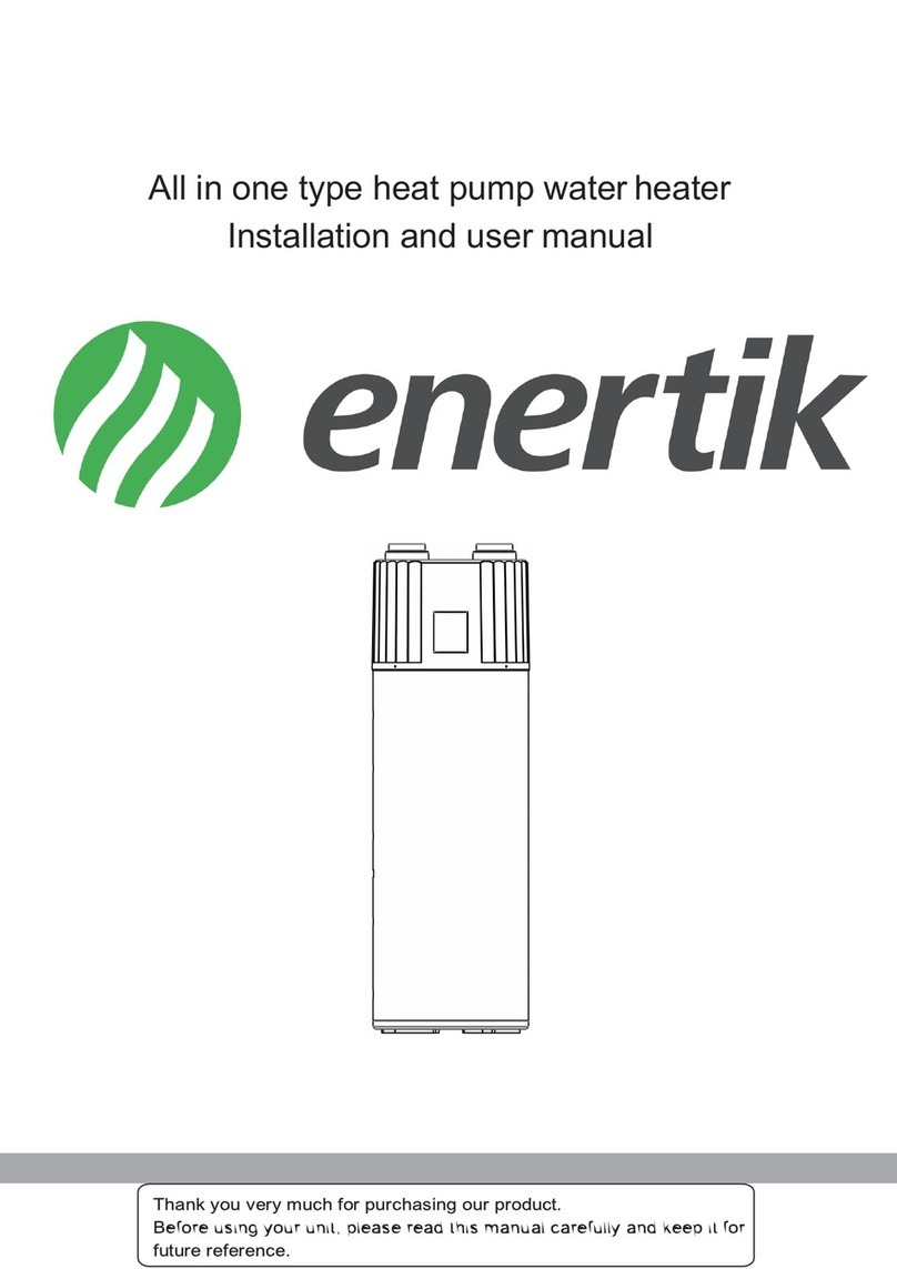
enertik BC-F20HWR2-200L Service manual

DOMESTIC INTEGRATED HEAT PUMP WATER HEATER
Installation & Instruction Manual
MODELS:
BC-F20HWR2-200L


Content
I. Foreword ..................................................................................................................... 1
II. Operation Instruction ................................................................................................ 2
III. Maintenance and Trouble Shootings ........................................................................ 5
IV. Technical Parameters ................................................................................................ 8
V. Installation ............................................................................................................... 10
VI. Circuit Specification and Wiring Diagram ............................................................... 12
VII. Wi-Fi Function ....................................................................................................... 14

1
I. Foreword
Please read the instruction carefully before install the unit, or we do not take any responsibility for the loss,
please take care of it for future reference (If updated, please refer to the latest version).
Safety warning
It may cause injures for people or damages for units if do not operate as following
Heat pump water
heater must be
installed by
Professionals.
The installation or
maintenance of the
unit must ensure that
the ground wire is
grounded safely and
reliably, and live
operation is strictly
prohibited.
Must use
220V-240V/50Hz
individual power supply.
Do not use mobile
socket, damaged
power cord and
socket.
Do not power
up until the
tank is filled with
water.
Do not put the
inflammable and
explosive material near
the unit.
Do not repair,
maintain, dismantle
or transform the unit
without permission .
Do not touch the plug
with wet hands.
Do not put your hands
or anything s close to
the air outlet and
blades.
In case of unit
abnormality, please
cut off the power
supply immediately
and contact our
personnel for
handling .
Safety notice
It may cause injures for people or poor performance of the unit if do not operate as following
Please cut off the power
supply and drain the
water from the heat pump
if it is not used for a long
time.
Please turn the water
temperature into 38~42℃
appropriately when
operating the unit.
Do not drink the water in
the heat pump directly.
The children must bath
under the guidance of
adult.
The water inlet and outlet
pipes of the unit must be
equipped with removable
filters.

2
To get better energy
saving effect, the unit
should be installed in
a good air-flowing
place .
Do not cut off the
power supply plugs to
turn off the heat
pump.
II. Operation Instruction
1. Panel Sign Description
Sign
Name
Sign
Name
Sign
Name
ON/OFF key
BATH sign
ERROR sign
TIME key
CYCLIC VENTILATION sign
STANDBY TIMING key
ELECTRIC HEATER key
ELECTRIC HEATER sign
SETTING key

3
DEFROSTING sign
HEATING sign
LOCK sign
UP key
DOWN key
2. Operation Guidance Table
NO.
Item
Operation Method
1
Unlock
Touch both the UP key and the DOWN key for 5s to
unlock.when unlocking, the LOCK sign is off.when
locking, the LOCK sign is on.
2
ON/OFF
Touch the ON/OFF key, the unit will turn off if the panel
is on and turn on if the panel is off.
3
Check Operation Parameters
The main interface displays the outlet water temperature
by default, touch SETTING key, then touch the UP key
and DOWN key to check each parameter.Short press the
ON/OFF key or no operation in 10s, exit the query state.
4
Select Mode
Touch the SETTING key and STANDBY TIMING key for
5s to enter forced manual defrost mode.
5
Temperature Adjustment
Press the SETTING key 5S to enter the system
parameter query, and query each parameter by
combining the UP key and DOWN key. In the system
query parameter state, press the SETTING key to set the
parameter, and set each parameter by combining the UP
key and DOWN key. The parameter serial number 0 is
the default setting temperature of the water tank, and the
parameter serial number 1 is the setting temperature of
the heating return difference.
6
Time Adjustment
Touch the TIME key, hour flashes, touch the UP key and
DOWN key to change the hour, touch the TIME key
again, minute flashes, touch the UP key and DOWN key
to change the minute. Touch the TIME key again to save
the change and exit the clock setting.

4
7
Timing Adjustment
Touch the TIME key 5s, hour of Period 1 start flashes,
touch the UP key and DOWN key to modify hours. Touch
the TIME key again, minute flashes, touch the UP key
and DOWN key to modify minutes.Continue to touch the
TIME key to enter the time setting of Period 1 end, the
operation is the same . Period 2 and period 3 are set in
the same way . If the start and end time settings of the
time period are the same, the time period is deemed to
be canceled .
8
Manual turn on electric heater
In the state of power on or off, press the ELECTRIC
HEATER key to enter or exit manual electric heating.
When manual electric heater is on, the electric heater
symbol lamp will be on.
9
Ventilation mode
Long press the ELECTRIC HEATER key to enter and
exit the ventilation mode.
10
Restore defaults
In the shutdown state, long press the ELECTRIC
HEATER key and SETTING key to restore factory
setting parameters.
11
Set system parameter
In any state, press SETTING key for 5 seconds, enter
the system parameter query interface, with UP key and
DOWN key to query each parameter.
In the system parameter query interface, press
SETTING key to enter the parameter setting interface;
with UP key and DOWN key to adjust parameter
setting.
3. Operation parameter table
NO.
State Name
Name
Display Range
Reservations
A
Water tank inlet temp.
℃
-9~99℃
Error code P1
B
Water tank outlet temp.
℃
-9~99℃
Error code P2
C
Coil temp.
℃
-9~99℃
Error code P3
D
Suction temp.
℃
-9~99℃
Error code P4
E
Ambient temp.
℃
-9~99℃
Error code P5
F
EEV opening
℃
10~48
N*10

5
H
Solar water tank temp.
℃
0~125(C7)℃
Error code P6
I
Exhaust temp.
℃
0~125(C7)℃
Error code P7
III. Maintenance and Trouble Shootings
1. Maintenance
l External cleaning: To clean the heat pump unit, the power must be cut off, and a small amount
of neutral detergent dipped in a wet cloth shall be used to gently wipe. Do not use gasoline or
acid solution, alcohol, and finally dry with a dry cloth.
l Waterway cleaning: Empty and clean once every 3 months. Descaling materials: clean with
organic acids such as formic acid, citric acid, acetic acid, etc.
l Evaporator cleaning:A hard nylon brush can be used to clean the fins of the evaporator.A
vacuum cleaner must be used Before cleaning. If there is compressed air, a high-pressure air
tube can be used to clean the fins of the heat exchanger.
l Note: If the solar coil is optional, if the ambient temperature is lower than 2℃, anti-freeze
valves and pipelines shall be installed in the solar coil water channel and filled with anti-freeze
liquid, such as glycerin-aqueous solution or ethylene glycol aqueous solution.
l Note: If the ambient temperature is lower than 2℃, please install circulating water pump on the
customer's water side to avoid freezing of pipeline during use. When the machine is out of
order, the water of the machine and the water side pipeline should be drained in time to avoid
freezing of the pipeline.The installation of water pump is shown in “Installation”.
Reference table of target concentration and target freezing point of unit antifreeze.
Glycerol
Local lowest ambient temp. (℃)
Antifreeze mass target concentration percentage (kg/kg %)
Antifreeze target
antifreeze point (℃)
0<T≤2
15
-3.2
-2<T≤0
20
-4.8
-4<T≤-2
25
-7.15
-6<T≤-4
30
-9.5
-8<T≤-6
35
-12.45
-12<T≤-8
40
-15.4
-17<T≤-12
45
-21.7
-25<T≤-17
50
-28
-29<T≤-25
55
-31.35
-31<T≤-29
60
-34.7
Glycol
Local lowest ambient temp. (℃)
Antifreeze mass target concentration percentage (kg/kg %)
Antifreeze target
antifreeze point (℃)

6
0<T≤2
10
-3.2
-2<T≤0
15
-5.4
-4<T≤-2
20
-7.8
-7<T≤-4
25
-10.7
-11<T≤-7
30
-14.1
-14<T≤-11
35
-17.9
-19<T≤-14
40
-22.3
-24<T≤-19
45
-27.5
-31<T≤-24
50
-33.8
-31<T≤-29
60
-34.7
Remarks: The mass percentage concentration C%=the mass of the solute/the mass of the
solution. The example shows that the historically lowest ambient temperature in Shanghai, China is
-12.1
℃
. Check the table above, and 45kg of glycerol should be added to the 100kg antifreeze
mixture as antifreeze, or 100kg of antifreeze mixture needs to add 40kg of ethylene glycol as
antifreeze.
2. Trouble shooting
Phenomenon
Reasons
Solutions
The unit doesn’t work.
1.No power supply.
1.Please wait for the power supply.
2.Power switch not on.
2.Open up the power switch.
3.Power switch fuse blown.
3.Replace fuse.
4.The timing time is not up.
4.Please wait or cancel the timing settings.
The unit does not work
when turns on.
1.Compressor protection interval not
reached.
1.Please wait the protection time to end patiently.
2.The unit water temperature does not reach
the starting water temperature.
2.It is normal phenomenon, wait for the starting
water temperature.
The unit works
normally, but the hot
water temperature is
low.
1.Improper temperature setting.
1.Set proper temperature.
2.Excessive hot water consumption.
2.Wait the hot water to warm up before using it.
3.The air inlet or outlet of outdoor unit or
indoor unit is blocked.
3.Remove the obstruction from the air inlet or
outlet.
The unit turns on
automatically.
1.The timing time is up.
1.If you do not want to use it, please turn off the
unit or cancel the timing settings.
Abnormal sound of the
unit.
1.There is too much dust or obstruction on
the air inlet of the unit evaporator, produce
strong and weak sound of wind.
1.Remove the dust or obstructions from the unit
evaporator.
2.The Refrigerant flow may produce some
noise when the unit turns on or turns off.
2.It is normal phenomenon.
3.No power on, the unit rings like 'dada' .
3.It is normal phenomenon, reset of EEV.

7
3. Error Code
Some faults may happen in the unit if the panel displays the
code as following during operating.please cut
off the power switch immediately, and reclose the power switch after 30 seconds , you can continue using
the unit if the code is not displayed, if the code is still displayed, please contact us for handling in time.
Error code
Protection/Error
Standby
Normal boot
P1
Water tank bottom temp. sensor failure
P2
Water tank top temp. sensor failure
P3
Coil temp. sensor failure
P4
Suction temp. sensor failure
P5
Ambient temp. sensor failure
P6
Solar temp. sensor failure
EC
Emergency switch failure
E1
High pressure protection
E2
Low pressure protection
4. System parameter
Code
Parameter
Range
Default
Note
0
Water tank temp.
10~75℃
60℃
Adjustable
1
Heating return difference temperature
2~15℃
5℃
Adjustable
2
Electric auxiliary heat start water tank
temperature TS2
10~85℃
65℃
Adjustable
3
Delay time of the electric auxiliary heater t1
0~90
1min
Adjustable (Real time=setting
value*5)
4
Electric auxiliary heater high temperature
disinfection stop temp.
50~75℃
75
Adjustable
5
High temperature disinfection maintenance
time t2
0~90min
30min
Adjustable
6
Heating defrosting cycle t3
30~90min
45min
Adjustable
7
Heating temperature point when start
defrosting TS4
-30~0℃
0℃
Adjustable
8
Heating exit defrosting temperature TS5
2~30℃
15℃
Adjustable
9
Heating exit defrosting time T4
1~12min
8min
Adjustable
10
EEV adjust mode
0/1
1
0- Manual, 1- Automatic
11
Target superheat degree
-9~9℃
2℃
Adjustable
12
Manual adjust EEV steps
10~47
30
N*10
13
High temperature disinfection start time
0~23hours
0
In the state of continuous power,
according to the set time once a
week
14
Solar water pump or not
0:Yes/1:Non
e
1
Adjustable

8
15
Temperature difference of solar water pump
start
2~20
10℃
Adjustable
16
Disinfection days set
7~28
7
Adjustable
17
Expansion valve min.steps(Ambient
temperature≥5℃)
8~15
10*10P
Adjustable
18
Expansion valve min.steps(Ambient
temperature<5℃)
8~10
8*10P
Adjustable
19
Defrosting expansion valve set
2~45
40*10P
Adjustable
20
Expansion valve allowed exhaust
temperature
70~120
100℃
Adjustable
21
Ambient temperature when allow defrosting
0~50
15℃
Adjustable
22
Temperature difference between ambient
and coil when start defrosting
1~20
2℃
Adjustable
23
Exhaust high temperature protection value
50~110
105℃
Adjustable
24
Compressor running time when start electric
heater
1~24hours
10hours
Adjustable
IV. Technical Parameters
1. Dimension
A
B
BC-F20HWR2-200L
570
1871

9
2. Parameter
Model:
BC-F20HWR2-200L
Power Supply
220-240V/50Hz
Max.Outlet Water Temp. (
℃
)
75
Rated Heating Capacity (kW)
1.75
Consumen Power (kW)
0.488
COP
3.58
Max. Power Input (kW)
3.906
Max. Running Current (A)
18.1
Water Tank Volume (L)
200
Hot Water Volume (L/h)
33
Water Connection (inch)
G3/4"
Noise dB(A)
55
Operation Temp. Range (
℃
)
-30~43
Refrigerant
R134a
Net Weight (kg)
110
Net Dimensions(L*W*H) (mm)
Φ570*1871
The parameters in the table are nominal values according to the rated working condition specified in EN
16147, which will change with working condition;
The above parameters are subject to product nameplate, if changed due to the product upgrade,
please kindly understand that we will not give prior notice.

10
V. Installation
1. Reservation Space
The minimum space required by the upward air outlet heat pump unit
2. Installation Schematic Diagram
WITH backwater control function
WITHOUT backwater control function

11
1
Pressure reducing valve
6
Circulating water pump
2
Water treating equipment
7
Water mixing valve
3
Y type filter
8
Temp.-Pressure relief valve
4
One-way valve
5
Frost valve
l The drain pipe of one-way pressure relief valve and condensate water drain pipe should be
maintained in communication with the atmosphere.
l The one-way pressure relief valve operates periodically to remove calcium carbonate deposits and to
certify that the installation is free of clogging.
l The drain pipe of the one-way pressure relief valve shall be installed in a continuous downward
manner in a frost-free environment.
l The connection between the unit and the water pipe must be equipped with cut-off valves or
removable loose connections.
l Water tank emptying operation: close the water replenishing valve, open the sewage gate valve, and
connect the water in and out of the water tank
(Watch out for burns!).
l For the area where the historical minimum ring temperature is lower than 2℃, the pipeline antifreeze
valve should be installed.
l For cold areas, it is necessary to install the user-side circulating water pump according to the
situation, so as to avoid icing of the user-side pipeline
l The condensate water outlet must be connected to the drain pipe.Prevent condensate water falling
off along the unit, causing unit intake water and rust.

12
VI. Circuit Specification and Wiring Diagram
1. The installation work of circuit wiring must be operated refer to the wiring diagram on the unit and
according to the requirements of national wiring specification by the professionals, and pay attention
to the following points during use:
l The power line and grounding shall meet the relevant national regulations and requirements for
safe power use. Make sure that the voltage is consistent with the nameplate, and whether the
carrying capacity of power supply, wire and socket is suitable for the inlet power of the
machine.
l Regulations of fuse tube: according to IEC, the rated current of fuse tube can be selected as
90% -100% of the rated maximum current of nameplate nominal value, and the maximum
non fusing current of overload capacity is 150% of the rated maximum power current of
nameplate.
l When the unit is installed outdoors, the power cord with plug shall not be used, and the
power cord used shall not be lighter than the neoprene armored flexible cord (line 57 in IEC
60245). The wire diameter specification of power cord, air circuit breaker, leakage circuit
breaker and load current comparison table.
Distribution Device And Power Cord of The Heat Pump Unit
Maximum current of
heat pump units(A)
Wire cross section(mm²)
Tripping current of air
circuit breaker(A)
Leakage circuit breaker
action current(mA)
<10
≥1.5
16
30
10~16
≥2.5
25
30
16~25
≥4.0
32
30
25~32
≥6.0
40
30
l When the power supply is connected, it must be equipped with full pole disconnecting device
and leakage protection device that match the unit and have a contact opening distance of at
least 3mm from the power supply. if the power cord is broken, it must be replaced by
professionals from the manufacturer, its maintenance department or similar departments to
avoid danger.
l After the power cord is installed and fixed firmly, pull the fixed power cord with a tension
meter of 100N, and the power cord moving distance should be less than 2mm, otherwise,
fix the power cord again, and the power cord wiring diagram:

13
l When finishing the work , switch on the power supply after carefully checking.
2. Wiring Diagram
The connection methods between the units and power supply and the interconnection methods of each
individual part should be according to the wiring diagram on the unit.

14
VII. Wi-Fi Function
1. Software Installation
① Method 1: Search “Smart life” in your APP store ,install “ ”.Clic k “GET ” to insta ll .
② Method 2: Scan the QR code below.
For IOS and Android Users
2. Software Startup
After installation,click “ ” on your desktop to start up Smart Life.

15
3. Software Registration and Configuration
1. Registration
① Users don’t have account can click “Register” to create an account: Register Enter your phone
number Get Verification Code Enter Verification Code Set Password;
② After registration, you need to Create a Home:Create a Home Set Home Name Set Home
Location Add Rooms.

16
2. Account ID+ Password Login
① Existing accounts can be logged in directly, in the following order.

17
② If you forget your password you can choose to login with your verification code and select "Forget
Password": Enter your phone number Get verification code .
③ After creating a home or logged in,enter the main interface of APP.
Other manuals for BC-F20HWR2-200L
1
Table of contents
Other enertik Water Heater manuals
Popular Water Heater manuals by other brands

A.O. Smith
A.O. Smith HeatBot Wi-Fi user manual

Ariston
Ariston GL 2.5 instructions

Worcester
Worcester WR 325 RSF User instructions & customer care guide

Lochinvar
Lochinvar Armor X2 AWN1000 Installation & operation manual

Rinnai
Rinnai Circ-Logic RU80i Installation and operation manual

Kenmore
Kenmore 153.572400 40 Use & care guide

Rinnai
Rinnai REU-A2626WG-ZK installation guide

GSW
GSW Signature Series Electric Catalog

Rinnai
Rinnai Infinity XR16 installation guide

Bradford White
Bradford White BW200-R Installation & operating instruction manual

Whale
Whale Expanse WL8212 operating instructions

Ariston Thermo
Ariston Thermo 120 Installation and maintenance instructions