Enervision TP600 Series User manual

TP600SERIES
INVERTER POWER SUPPLY
USER MANUAL

General Instruction
This chapter contains important safety and operating instructions.
Read and keep this User Guide for later reference.
Before using TP600, read and follow all instructions and caution
marking on TP600, the batteries, and in all sections of this
instruction manual.

-i-
Contents
1.Important Safety Instruction...............................................................................................................1-1
1.1 Safety Instruction.............................................................................................................................. 1-1
1.2 General Precaution ...........................................................................................................................1-1
1.3 Precaution for battery ....................................................................................................................... 1-1
2.Foreword ...............................................................................................................................................2-1
2.1 Instruction......................................................................................................................................... 2-1
2.2 Feature ..............................................................................................................................................2-1
2.3 Specification and Technical Data......................................................................................................2-2
2.3.1 Technical Data ........................................................................................................................2-2
2.3.2 DC input voltage and operate range .......................................................................................2-3
3.Principle of Design................................................................................................................................3-1
3.1 Block Diagram..................................................................................................................................3-1
3.2 Operation Mode ................................................................................................................................ 3-1
3.2.1 AC mode .................................................................................................................................3-1
3.2.2 DC mode................................................................................................................................. 3-1
3.3 Outline and LED Indicators.............................................................................................................. 3-2
3.3.1 Outline ....................................................................................................................................3-2
3.3.2 Front panel.............................................................................................................................. 3-4
3.3.3 Rear panel ............................................................................................................................... 3-5
3.3.4 LED indicators........................................................................................................................ 3-6
4.Installation.............................................................................................................................................4-1
4.1 Preparation........................................................................................................................................4-1
4.1.1 Tool, Information ....................................................................................................................4-1
4.1.2 Ambient Condition..................................................................................................................4-1
4.1.3 Connect the Cable................................................................................................................... 4-1
4.1.4 Inspection................................................................................................................................4-2
4.2 Installation ........................................................................................................................................4-2
4.2.1 Rack model .............................................................................................................................4-2

-ii-
4.2.2 Tower model........................................................................................................................... 4-4
5.Operation.............................................................................................................................................. 5-1
5.1 Power ON/OFF ................................................................................................................................ 5-1
5.1.1 First power ON....................................................................................................................... 5-1
5.1.2 General operation ................................................................................................................... 5-1
5.2 Operation.......................................................................................................................................... 5-1
5.2.1 POWER ON ........................................................................................................................... 5-1
5.2.2 Shutdown................................................................................................................................ 5-2
5.2.3 Inaudible................................................................................................................................. 5-2
6.Operation Mode and Status Display................................................................................................... 6-1
6.1 LED Indicator and Button Definition............................................................................................... 6-1
6.2 LCD Interface................................................................................................................................... 6-2
6.3 Work status ....................................................................................................................................... 6-2
6.3.1 Standard model....................................................................................................................... 6-2
6.3.2 Professional model ................................................................................................................. 6-5
7.Alarm、Remote Control ..................................................................................................................... 7-1
7.1 Alarm signal and Error code description .......................................................................................... 7-1
7.2 Remote control and Alarm ............................................................................................................... 7-2
7.2.1 Communication port............................................................................................................... 7-2
7.3 Troubleshooting................................................................................................................................ 7-3

Inverter power supply user’s manual
1-1
1.Important Safety Instruction
1.1 Safety Instruction
As dangerous voltages and high temperature exist within the INVERTER, only
qualified maintenance personnel are permitted to open and repair it.
This manual contains information concerning the installation and operation of the
TP600。All relevant parts of the manual should be read prior to commencing the
installation.
Such actions are not warranted as operating against safety requirement or against
design, manufacture, safety standard, and are out of the service responsibility.
1.2 General Precaution
1.Do not expose TP600 to rain, snow or liquids of any type,it is designed for indoor
use. To reduce risk of damage, do not block off ventilation, or otherwise the
INVERTER would be overheating.
2.To avoid fire and electric shock,make sure all cables selected with right gauge
and connected well。Smaller diameter and broken cable are not permitted to use.
1.3 Precaution for battery
1.Keep plenty of fresh water and soap at hand in case battery acid contacts skin,
clothing, or eyes.
2.NEVER smoke or allow a spark or flame in vicinity of a battery。
3.Do not put the metal tool on the battery; spark and short circuit will lead to
explosion.

Inverter power supply user’s manual
1-2
4.Remove personal metal items such as rings, bracelets, necklaces, and watches
when working with batteries. Batteries can cause short-circuit current high enough
to make metal melt, and could cause severe burns.

Inverter power supply user’s manual
2-1
2.Foreword
2.1 Instruction
TP600SERIES INVERTER is designed for DC/AC application especially for high
qualify require environment like as communication and electric power field.
2.2 Feature
zDSP (Digital Signal Processing) Controller: The DSP monitors the unit output state
in real time, and provides excellent transient response comparing to the intelligent
program.
zPWM+SPWM (Pulse Width Modulation + Switch Pulse Width Modulation): PWM
technology is used to supply pure and stable power for 3% distortion and 2%
stability pure sine wave.
zAdvanced isolation technology between DC and AC, meet safety and EMC
requirement of system.
zIdeal Self-diagnosis function: The DSP is to monitor the system operation.
zAutomatic Bypass: Under the circumstance of DC input faulty or servicing the
battery, the main power will switch to load automatically via the built-in Bypass
circuit and the power is supplied by input side directly.
zSelectable input frequency ranges 44Hz~66Hz, with output frequency is 50Hz or
60Hz.
zAuto restart: When the utility mains reactivation, the unit will restart automatically.
zIdeal protection function: When the system is in abnormal condition or other
protection mode like Over Current Protection, Over Voltage Protection, Over
Power Protection, and Over Temperature Protection, or the components is failure,
the DSP will take actions.
zAdvanced technology of reducing reflected noise, no disturbance to other
equipments connected on the same DC distribution frame, multicomplex filtering in
AC input to eliminate the utility interference, meeting the requirement for default
AC status.
zTwo operation modes: A and D
A) Type A: When AC mains power is normal, unit operates on AC mode. In case
AC mains power is abnormal, unit transfer to inverter mode.
B) Type D: When DC mains power is normal, unit operates on inverter mode. In
case DC mains power is abnormal, unit transfer to AC mode.
zMulti-function LED indicators and LCD interface and buzzer alarms.
z3 dry contact provided for alarm of DC input undervoltage, AC input fault,

Inverter power supply user’s manual
2-2
equipment faulting.
zStandard RS232 communication port: the unit can be controlled and managed by
the monitoring software.
zConnect external SNMP card to transmit the data between the unit and PC.
2.3 Specification and Technical Data
2.3.1 Technical Data
Rating 500VA 1000VA 1500VA 2000VA 3000VA 4000VA 5000VA 4000VA 5000VA
Rated DC Input Voltage 48V/110V/220V 110V/220V 48V
DC Operating Range 48V/110V/220V -18% ~48V/110V/220V +25%
Input Reflected Noise Input voltage and load current rated: less than 10%
AC Input Voltage 230V-25% ~230V+20%
Input Frequency 50Hz±10%
AC Output Voltage 230V±2%
Output Frequency 50Hz±0.1%
Rated Output Current 1.7A 3.5A 5.2A 7.0A 10.4A 13.9 17.4 13.9 15.2
Power Factor 0.8 0.7
THD ≤3%
Transient Response Load from 0 to 100%,less than 30ms
Bypass Transfer Time <5ms
Overload AC mode:120%/3min,150%/30sec
INVERTER mode:120%/30sec,150%/10sec
Efficiency >88%
Protection Overload – short circuit – overvoltage – undervoltage – thermal
Interface LED+LCD
Communication Port RS232
Dry Contact Yes
Electric Strength Conform to EN62040-1-1
Noise(1m)≤45dB
Ambient Temperature(℃) -10℃~45℃
Relative Humidity 0-95% no dew
Altitude(m)<1500
Rack
W×H×D(mm)482×88×250 482×88×330 516×88×320
Weight(Kg)5.7 6.2 6.5 9 9.9 12.5 13.5 13.5 14.7
Tower
W×H×D(mm)158.5×214.2×461 183.5×293×506 183.5×293×570
Weight(Kg)7.6 8 8.3 12 12.9 14 15 14 15

Inverter power supply user’s manual
2-3
2.3.2 DC input voltage and operate range
Rated voltage 12V 24V 48V 110V 220V
Power ON voltage 10.5~14.8 21~29.5 42~59.5 96~136 192~272
DC operated range 10~14.8 20~29.5 40~59.5 91.5~136 183~272
Low warning voltage 11 22 44 101 202
Notes:
1. To protect battery ,TP600 only powered ON as battery voltage in DC operated
range.
2. When battery voltage is lower to the level of warning point then audible alarm is start up.
In case the battery voltage is lower than the limit, unit will shut down.


Inverter power supply user’s manual
3-1
3.Principle of Design
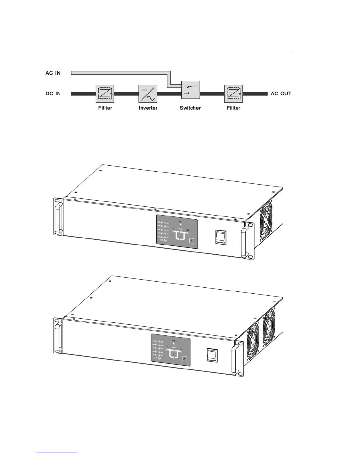
3.1 Block Diagram
Note:TP600 based on PWM+SPWM high frequency technology with DSP as control.
It is ideal form of protection for all important data processing and telecommunication
applications.
Block Diagram
3.2 Operation Mode
3.2.1 AC mode
That is A operation mode: When mains power is normal, TP600 works in mains mode
or inverter mode in case mains is failure.
3.2.2 DC mode
That is D operation mode: In ,inverter works all the time in the event of DC failure, unit transfers to
Inverter power supply user’s manual
3-2
bypass mode.
3.3 Outline and LED Indicators
3.3.1 Outline
Rack standard model
0.5~1.5KVA
2~5KVA

Inverter power supply user’s manual
3-3
Rack professional model
0.5~1.5KVA
2~5KVA
Inverter power supply user’s manual
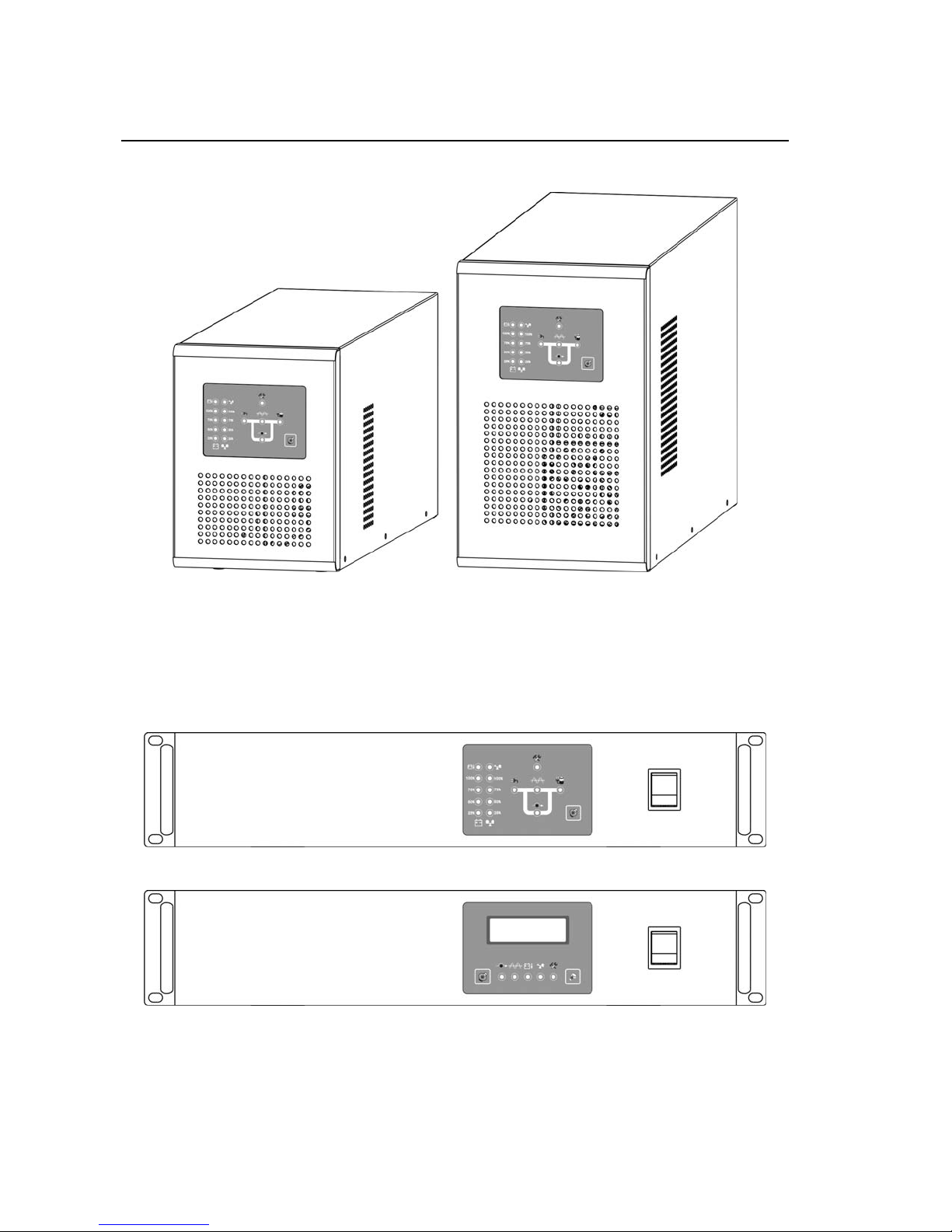
3-4
Tower model
0.5~1.5KVA 2~3KVA
3.3.2 Front panel
Rack standard model
Rack professional model
Inverter power supply user’s manual
3-5
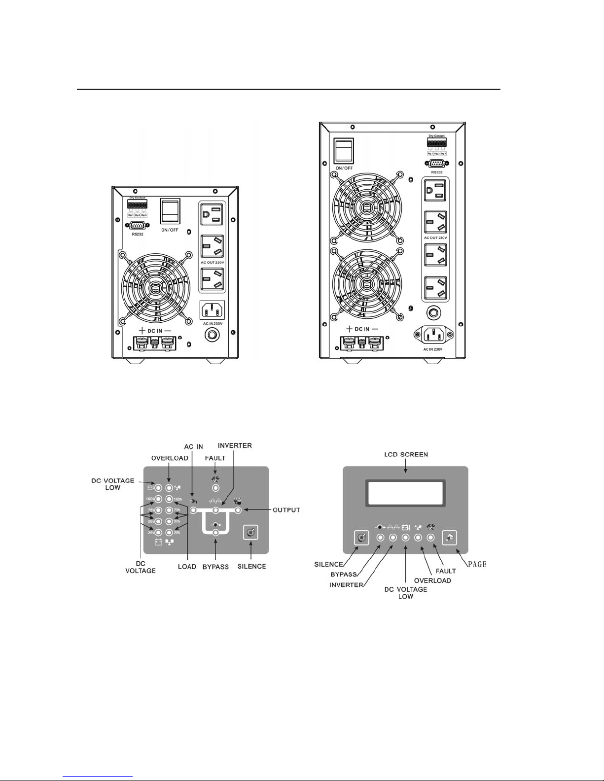
Tower model
0.5~1.5KVA 2~3KVA
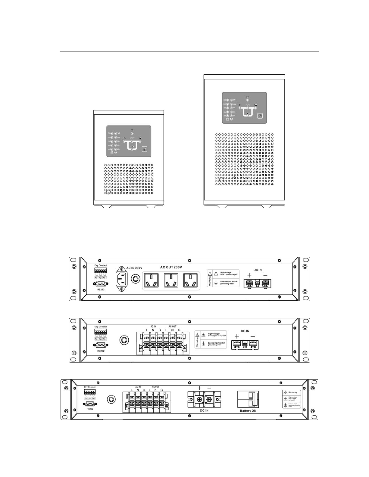
3.3.3 Rear panel
Rack standard model
Rack simplified model
Rack simplified model 4~5KVA 48V
Inverter power supply user’s manual
3-6
Tower model
0.5~1.5KVA 2~3KVA
3.3.4 LED indicators
Standardmodel Professionalmodel

Inverter power supply user’s manual
4-1
4.Installation
4.1 Preparation
Only a technician is permitted to install the unit.
4.1.1 Tool, Information
Multi-meter、tool box、user manual、cable
4.1.2 Ambient Condition
Environment requirements:
zWorking temperature:0-40℃
zStorage temperature:-40-70℃
zRelative Humidity:0%-95%,no dew
zCooling:nature
zAltitude:1500m, meet derating requirements in GB3859.2-93
zVertical angle:No vibration and hading angle less than 5 degree
zPollution:Class II
Working temperature of 20~25 and Humidity of 50% are recommended.
Caution
The INVERTER must be installed in a location with good ventilation, far away
from water, inflammable gas and corrosive agent.
4.1.3 Connect the Cable
AC input power cord:Tower and Rack Standard model use the cord prepared by
manufacture, but user should prepare the cord for Rack
Simplified model and terminal block is installed on rear panel.
Recommended size of cable:
Rating Diameter of cable
500VA 0.75mm 2
1000VA 1mm 2
1500VA 1.5mm 2
2000VA/3000VA 2.5mm 2
4000VA/5000VA 4 mm 2

Inverter power supply user’s manual
4-2
AC output cord:Choose by user
DC input cord:Recommended size of cable:
Rating Diameter of Cable
48V 110V 220V
500VA 2.5 mm 21mm 20. 5mm 2
1000VA 4 mm 21.5 mm 21mm 2
1500VA 6 mm 22.5 mm 21.5mm 2
2000VA 10 mm 24 mm 22.5mm 2
3000VA 16 mm 26mm 22.5mm 2
4000VA/5000VA 25 mm 210mm 24 mm 2
4.1.4 Inspection
Unit should be saved on the right environment and the term for preserving is
less than 3months.
Before installation, unit should be placed on the spot. Unpack the package
and check the package contents. Keep all spare part and accessories for future
use.
4.2 Installation
4.2.1 Rack model
1.Install handle
Take out two L brackets and handles from packing bag and use M4 to fix
them on the left and right sides of unit. Figure as below:

Inverter power supply user’s manual
4-3
2.Place the unit
Put the unit on the right location of 19inch rack(Caution:Additional support
must be added as bottom!). Try to push the unit from the front and side to see it
moves; and repeat the above actions until it is firmly secured..
3.Cable Connection
1)Connect DC input cable
Following battery polarity guide marked on rear panel! Place the battery cable
over TP600’s DC terminal.
For the user operation safety, cut off the power when install the unit!
2)Connect AC input and output
Use right cable according to different terminal of rear panel.
For Standard model: take out the cable in accessories, plug the cable into
the socket of rear panel showed as follow figure:
For Simplified model: use terminal block and notice LINE , NETURAL and
polarity:

Inverter power supply user’s manual
4-4
4.2.2 Tower model
1.Fix up
Install the unit in any protected environment that provided adequate airflow
around the unit, and is free from water. Also, place the unit away from the object at
least 20cm around the unit.
2.Cable Connection
Refer to Rack Standard Model. Figure as below:
Table of contents


