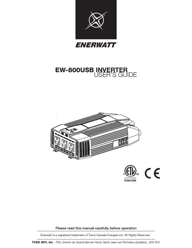
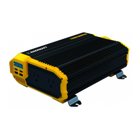
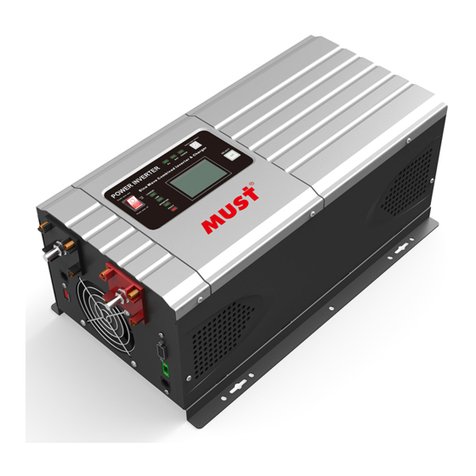
Enerwatt EW-3000 User manual

E113479
Complies with UL 458
CSA C22.2 No. 107.1
TC Energies - 700, chemin du Grand Bernier Nord, Saint-Jean-sur-Richelieu (Québec) J2W 2H1
Please read this manual carefully before operation
EW-3000 AND EW-4000 INVERTER
USER’S GUIDE
Enerwatt is a registered trademark of Trans-Canada Energies inc. All Rights Reserved.
Version française à la page 17

2
Welcome
Please read this manual thoroughly before installing and operating your new Enerwatt Power
Inverter. This manual contains information you need to obtain the performance required for
your application. Keep this manual for future reference.
This Enerwatt Inverter converts low voltage, direct current (DC) to 110 volt modied Sine wave
(MSW) alternating current (AC). The inverter draws power from 12 volt deep-cycle batteries
such as those used for marine applications, golf cart, and fork-lift or from other high current 12
volt sources.
This model, EW-3000 / EW-4000, has been performance tested by MET and complies with Un-
derwriter’s Laboratories and Canadian Standards Association safety standards.
A Higher Wattage Inverter May Be Required
To determine whether the Enerwatt EW-3000 / EW-4000 will operate a particular appliance or
a combination of appliances, run a test. All inverters are designed to automatically shut down
in the event of a power overload. This protection feature prevents damage to the unit while
running appliances with combined wattages below the 3000 / 4000 watt range. Turn on the
highest wattage appliance rst then other appliances (one after the other). If an appliance
combination in the 3000 / 4000 watt range does not operate properly, then it is likely that this
Enerwatt inverter does not have the required capacity to operate the appliance(s) in question.
WARNINGS, CAUTIONS AND NOTES
It is very important that any operator and installer of this inverter read and follow all WAR-
NINGS, CAUTIONS AND NOTES and all installation and operation instructions. In particular,
comply with WARNINGS (possibility of serious injury or death), CAUTIONS (possibility of da-
mage to the inverter and / or other equipment), and NOTES (included to assist you in achieving
the maximum performance and longest working life from this advanced-design inverter).
WARNINGS: INVERTER OUTPUT
This is a heavy-duty device that produces voltages similar to commercial AC power.
• Danger of shock or electrocution - treat inverter output the same as commercial AC power.
• Do not use the inverter near ammable materials or in any locations that may accumulate
ammable fumes or gases. This is an electrical device that can briey spark when electrical
connections are made or broken.
• Do not allow water or other liquids to contact the inverter.
• Do not use appliances with damaged or wet cords.
CAUTIONS: INVERTER OPERATING ENVIRONMENT
• Surrounding air temperature should be between 4 °F and 104 °F (-20 °C and 40 °C) – Ideally
between 60 °F and 80 °F (15 °C and 25 °C).
• Keep the inverter away from direct sunlight if at all possible.
• Keep the area surrounding the inverter clear to ensure free air circulation around the unit.
Do not place items on or over the inverter during operation. The unit will shut down if the
internal temperature gets too hot. Restart the inverter after it cools.
• This Enerwatt inverter will only operate from a 12 V power source. Do not attempt to
connect the inverter to any other power source, including any AC power source.
• Do not reverse DC input polarity – this will systematically void the warranty.

3
APPLIANCE CAUTIONS
• Do NOT plug in battery chargers for cordless power tools if the charger carries a warning
for presence of dangerous voltages at the battery terminals.
• Certain chargers for small nickel-cadmium or nickel-metal-hydride batteries can be damaged
if powered by this inverter. Two types of appliances are susceptible to get damaged:
o Small, battery-operated appliances such as ashlights.
o Cordless razors and toothbrushes that plug directly into an AC receptacle.
• Do NOT use this inverter with the above two types of equipment.
• The majority of portable appliances do not have this problem. Most portable appliances
use separate transformers or chargers that plug into AC receptacles to supply a low-vol-
tage DC or AC output to the appliance. If the appliance label states that the charger or
adapter produces a low-voltage DC or AC output (30 volts or less), there will be no pro-
blem powering that charger or adapter.
• Some fans with synchronous motors may slightly increase in speed (RPM) when powered
by the inverter. This is not harmful to the fan or to the inverter.
• Route appliance cords and extension cords to prevent accidental cable pinching, crushing
or abrading and tripping people.
• Use safety approved extension cords rated at 15 amps or higher.
• GFCI devices may not work with modied sine wave (MSW) power.
• This inverter is not tested for use with medical equipment.
• This inverter is not tested for use in marine applications.
• In the event of a continuous audible alarm or automatic shutdown, turn the inverter OFF
immediately. Do not restart the inverter until the source of the problem has been identi-
ed and corrected.
• When attempting to power lead acid battery chargers, with modied sine wave, monitor
the temperature of the battery charger for approximately 10 minutes. If the battery
charger becomes abnormally warm, immediately disconnect it from the inverter.
Getting Started
A motorized appliance or a tool require an initial surge of power to start up. This surge of power
is referred to as the“starting load”or“peak load.”Once started, the tool or appliance requires less
power to operate. This is referred to as the“continuous load”in terms of power requirements. You
will need to determine how much power your tool or appliance requires to start up (starting load)
and its continued running power requirements (continuous load).
Power consumption is rated in watts, or it can be calculated from amperes (amps). This informa-
tion is usually stamped or printed on most appliances and equipment. If this information is not
indicated on the appliance or equipment, check the owner’s manual. For electrically sensitive
equipment, contact the manufacturer to determine if the device you are using is compatible with
an AC modied sine wave inverter.
Multiply: AC AMPS X 110 (AC voltage) = WATTS
This formula yields a close approximation of the continuous load of your appliance.
Multiply: WATTS X 2= Starting Load for most appliances
This formula yields a close approximation of the starting load of most appliances. Exceptions
are motorized appliances such as pumps, freezers and air conditioners. These appliances can
have start-up loads of up to eight times the rated watts.

4
Front Panel EW-3000 / EW-4000
A. LCD Digital Display (See LCD Diagram).
B. POWER Button: pressing the button turns the inverter circuits ON and OFF.
C. MENU Button: pressing the button will change the display between OUTPUT WATTAGE
and INPUT VOLTAGE.
D. Two standard North American AC outlets, each rated at 15 Amps (1650 Watts).
E. Two USB ports (2.1 Amp shared): allows the user to power one or two single 2.1 A
compatible tablet devices or two 1A USB-charging devices, such as cell phones.
LCD Diagram
1. Battery Level.
2. Output wattage (W) or input voltage display (VDC).
3. Warning indicator:
a. High voltage
b. Low voltage
c. Voltage overload
5. Temperature shutdown.
W
HIGHLOW VOLTAGEOVERLOAD

5
Hardwire Instructions EW-3000 / EW-4000
First make sure the unit is completely disconnected from any power source and that themain
power is completely OFF. Begin by unscrewing the front plate which is located under the 2 x AC
outlets at the front of the inverter.
You will then see the 3 connecting terminals, as illustrated below:
H: HOT
N: NEUTRAL
E: EARTH (GROUND)
The recommended Gauge wires are:
EW-3000: Jacketed No. 10 Gauge copper 2-wires
EW-4000: Jacketed No. 8 Gauge copper 2-wires
Some installation codes are required and we recommend use of oil-resistant cables rated for
damp or wet locations. We would strongly recommend having this installed by a certied elec-
trician since these wires will have a live current, if installed improperly, can cause a re or shock
hazard.
Once installed, have the wires come through the front plate by removing the middle circle of
the front plate. Once all connections are secure and properly installed and front plate is secured
back onto the front or the inverter, you can then turn the inverter back ON to test out the AC
connection. Make sure to test the AC output from newly installed wires with a TRUE RMS volt
Meter prior to operating from the Hard Wire connection.

6
Rear Panel EW-3000 / EW-4000
F. High-Speed Cooling Fans. When the temperature inside the inverter exceeds its preset
limit, the Cooling Fans automatically turn on to cool the inverter. When the temperature
reduces, the fans turn o.
G. Positive Power Input Terminal.
H. Negative Power Input Terminal.
I. Remote Control Receptacle.
J. Ground Terminal.
K. Main Switch is used to completely shutdown the inverter.
Determining the DC Power Requirements
Powering multiple appliances from the high-power EW-3000 / EW-4000 inverter requires a
12 volt battery bank (several batteries). To calculate the approximate power in amps a 12 volt
battery bank has to supply, you need to know: the current, or amps required for powering the
continuous AC load, a shortcut method is to divide the continuous AC load wattage by 10. For
example, the continuous AC load is 3000 watts. The current (amps) is: 3000/10 or 300 amps at
12 V DC.

7
Sizing the Battery Bank
To determine the minimum battery bank ampere-hour (Ah) rating that you will need to operate
appliances from the inverter, and any DC appliances powered by the battery bank, follow these
steps:
1. List the maximum wattage that the inverter has to provide (as above).
2. Estimate the number of hours the appliances will be in use between battery
recharges. This will dier depending on appliances. As an example, a typical home-
use coeemaker draws 500 watts during its estimated 5 minute brew time; it main-
tains the temperature of the pot at about 100 watts. Typical use of a microwave
oven is only for a few minutes. Some longer operating time appliances are lamps,
TVs, computers and refrigerators / freezers.
3. Determine the total watt-hours of energy needed. Then multiply the average power
consumption in watts by the number of hours of run time. For example: 3000 watts
for 10 hours = 30,000 watt-hours. Using the 3000 watts (or 300 Amps) for 10 hours
example as above, then 300 amps are needed for 10 hours. This provides us with
the basic amp-hours (Ah) of battery that is required. Ten hours at 300 amps equals
3000 amp-hours (Ah).
This is just an approximate estimation, as there are other conditions that determine
the actual run time. These include:
• AC appliance load and time in use (basic amp-hour)
• Cable gauge and length (cable losses)
• Charge level of the batteries (between use, chargers have to be able to fully
charge the batteries)
• Temperature of the batteries (colder batteries provide fewer amps)
• Age and condition of the batteries (older batteries lose capacity/amp-hour)
• Compliance with turning o unnecessary AC and DC loads. If there is any
doubt about sizing the battery bank, it is safe to overestimate the amp-hour
requirements of the battery bank.
Note:
The type of batteries you use to power your power inverter is important. Operating a high-
power inverter will routinely discharge batteries and they will require frequent recharging.
Batteries used to start engines are not designed to repeatedly charge and discharge. Enerwatt
recommends using“deep-cycle”or“marine”rated batteries.
Cable Gauges
When connecting the inverter to a battery bank use the thickest stranded insulated copper
wire available, in the shortest practical length. Recommended cable gauges are as follows:
Model
EW-1100 4AWG (3 ft. included W/ 110A inline ANL Fuse)
EW-2000 2AWG (3 ft. included W/ 200A inline ANL Fuse)
EW-3000 0AWG (3 ft. included W/ 300A inline ANL Fuse)
EW-4000 0AWG (3 ft. included W/ 400A inline ANL Fuse)
Recommended Gauges

8
WARNING: DANGER OF BATTERY EXPLOSION – INSTALL A FUSE
Battery banks can deliver very high levels of current that can vaporize metal, start res and
cause explosions. Enerwatt recommends installing one ANL type fuse and fuse holder close to
the positive battery bank terminal. This fuse protects the batteries from accidental DC cable
shorts, which can cause batteries to explode. ANL fuses and fuse holders are available at most
marine supply stores.
CAUTIONS:
• Loose connections can result in a severe decrease in voltage that can cause damage to
cables and insulation.
• Failure to make correct polarity (positive, negative) connection between the inverter and
the battery bank can result in blowing fuses in the inverter that may permanently damage
the inverter. Enerwatt Warranty does not cover damage caused by reversed polarity.
• Making the connection to the positive terminal may cause a spark as a result of current
owing to charge capacitors within the inverter. This is a normal occurrence.
• Because of the possibility of sparking, however, it is extremely important that both the
inverter and the 12 volt battery be positioned far from any possible source of ammable
fumes or gases. Failure to heed this warning could result in re or explosion.
• Operating the inverter without correctly grounding the unit may result in electrical shock.
Mounting the Inverter
Your Enerwatt Inverter should not be mounted under the hood of a vehicle.
If installing in a vehicle, choose a dry, cool, ventilated area closest to the battery as practical. Be-
fore drilling any mounting holes, make sure that there are no wires, fuel lines, or tanks directly
behind the surface to be drilled. To mount the inverter:
1. Inverter must be OFF.
2. The inverter should be mounted horizontally.
3. Position the inverter against the mounting surface and mark locations of the mounting
screw openings.
4. Remove the inverter and drill four mounting holes.
5. Fasten the inverter to the mounting surface using corrosion-resistant fasteners sized #10
or larger.
Connecting the Inverter
This inverter has two DC cable connections, one positive and one negative. The order of steps
in the following procedure minimizes the danger of sparking near the battery bank.
1. Prepare all cable set ends with ring terminals at the battery ends.
2. Install one fuse holder with fuse in the Positive (+) cable close to the battery bank end.
3. Make sure the inverter is OFF.
4. Ensure all appliance cords or extension cords are disconnected from the inverter.
5. Connect an appropriate stranded insulated wire to the enclosure ground terminal and
connect the free end of the wire to the vehicle’s chassis or any other ground point.
6. Connect the unfused cable to the Negative (-) terminal of the battery bank.
7. Connect the Negative cable to the Inverter’s Negative (-) terminal.
8. Insulate the end of cable to be connected to the Positive (+) inverter terminal.
9. Connect the fused cable to the battery bank Positive (+) terminal.
10. Connect the Positive cable end to the Positive (+) inverter terminal.
NOTE: Sparking is normal for the rst connection.
Make sure you have good secure connections – Do not over-tighten.

9
Operation
1. Turn On the inverter.
2. Turn OFF the inverter.
3. When you have conrmed that the appliance to be operated is turned o, plug an ap-
pliance cord into one of the two 110 V AC Outlets on the front panel of the inverter.
4. Turn ON the inverter.
5. Turn the appliance on.
6. Plug in additional appliances and turn them on.
Note:
The audible alarm may make a momentary “chirp”when the inverter is turned OFF. This same
alarm may also sound when the inverter is being connected to or disconnected from the 12
volt battery bank.
Television and Audio Suggestions
Although all Enerwatt inverters are shielded and ltered to minimize signal interference, some
interference with your television picture may be unavoidable, especially in weak signal areas.
However, here are some suggestions that may improve reception:
1. First, make sure that the television antenna produces a clear signal under normal ope-
rating conditions. Also, ensure that the antenna cable is properly shielded and of good
quality.
2. Change the positions of the inverter, antenna cables and TV power cord.
3. Isolate the TV, its power cord and antenna cables from the 12 volt power source by run-
ning an extension cord from the inverter to the television set.
4. Coil the television power cord and the input cables running from the 12 volt power source
to the inverter.
5. Attach a“Ferrite Data Line Filter” to the television power cord. More than one lter may be
required. These lters are available at most electronic supply stores.
Note:
Some inexpensive audio systems may produce a slight“buzzing”sound when operated with
the inverter. The only solution to this problem is to use a sound system with better power
supply ltering.
Operating a Microwave oven with your Power Inverter
The power rating used with microwave ovens is the “cooking power” which means the power
being“delivered”to the food being cooked. The actual operating power rating is listed on the
back of the microwave. If the operating power cannot be found on the back of the microwave,
check the owner’s manual or contact the manufacturer.

10
How this Modified Sine Wave Power Inverter Works
There are two stages in which this power inverter changes the 12 volt DC (or battery) power to
110 V AC (household current).
STAGE 1:
This inverter uses a DC to DC converter to increase the DC input voltage from the battery to 145
volts DC.
STAGE 2:
The inverter then converts the high voltage DC into 110 V AC (household current), using
advanced MOSFET transistor in a full bridge conguration. This design provides this Enerwatt
inverter with the capability to start and run dicult reactive loads, while providing excellent
overload capability. The waveform that is generated by this conversion is a“modied sine wave”
as shown in the diagram below.
Best use of Battery Power
Make sure any appliances are energy ecient and turned o after use.
Use uocompact lamps. Wherever possible, charge with a renewable energy system (solar or
wind generator systems). Do not allow lead acid batteries to remain discharged for longperiods
of time, they lose capacity (Ah).
Please recycle in proper disposal site
Electronic products are known to contain materials that are toxic if improperly disposed.
Contact local authorities for disposal and recycling information.
This inverter is certied to be “lead free.”Transformers in this inverter contain nickel composites.
Nickel is a known neuro-toxin if ingested.
SINE WAVE MODIFIED SINE WAVE (MSW)

11
Troubleshooting
PROBLEM: No Input voltage
Reason Solution
Poor contact with battery terminals.
Shut down inverter and disconnect.
Clean terminals thoroughly and
reconnect.
Blown DC battery fuse(s).
Turn o inverter. Fix problem.
Replace fuse(s) with same type and
same rating.
PROBLEM: Inverter is Shut Down
Reason Solution
Battery voltage below 10 volts. Charge or replace battery.
Inverter is too hot (thermal shut down
mode). Will be indicated on LCD
panel.
Allow inverter to cool. Check for
adequate ventilation. Reduce the
load on the inverter to rated conti-
nuous power.
Unit may be defective. See warranty and call customer
service.
PROBLEM: Low Battery Alarm on all the Time
Reason Solution
Input voltage below 10.5 volts. Will
be indicated on LCD panel.
Keep input voltage above 10.5 volts
to maintain regulation.
Poor or weak battery condition. Recharge or replace battery.
Inadequate power being delivered
to the inverter or excessive voltage
drop.
Use lower gauge (heavier) cable.
Keep cable length as short as posible.
PROBLEM: TV does not Work
Reason Solution
TV does not turn on.
Contact TV manufacturer to nd out
if the TV is compatible with a
modied sine wave.

12
Specications: EW-3000
Specications Description
Output Continuous Watts (W) 3000 W + 10 W (USB)
Surge Capacity (Peak Power) 6000 W
Rated Input DC (V,A) 12 VDC, 322 A
Input voltage Range 10.5 to 15.5 VDC +/- 0.3 V
Rated Frequency (Hz) 60 Hz ±1
Rated Output AC (V,A) 115 V +/- 10 %, 26 A
Rates Output USB (V,A) 4 * 5 V/max. 2.1 A (iPad)
No Load Current <0.9 A DC
Optimum Eciency 90 % min.
Fuse (A) (125 A*3)
Fuse Type Internal Blade
Output Wave Form Modied Sine Wave
Max. Touch Temperature 65 °C Max
Operating Temperature 0 to 40 °C
Operating/Storage Humidity RH 5 to 95 %
Cooling System Thermo Fan
THD 10 to 45 %
Dimensions LxWxH (inches) 13.19 x 5.67 x 4.88
Assembled Weight (LBS) 7.58
NOTE:
All specications are typical at nominal line, half load, and 77 °F (25 °C) unless
otherwise noted. Specications are subject to change without notice.

13
Specifications: EW-4000
Specications Description
Output Continuous Watts (W) 4000 W +10 W(USB)
Surge Capacity (Peak Power) 8000 W
Rated Input DC (V,A) 12 VDC, 430 A
Input voltage Range 10.5 to 15.5 VDC +/- 0.3 V
Rated Frequency (Hz) 60 Hz ±1
Rated Output AC (V,A) 115 V +/- 10 %, 34.8 A
Rates Output USB (V,A) 4 * 5 V/max. 2.1 A (iPad)
No Load Current <0.9 A DC
Optimum Eciency 90 % min.
Fuse (A) (150 A*3)
Fuse Type Internal Blade
Output Wave Form Modied Sine Wave
Max. Touch Temperature 65 °C Max
Operating Temperature 0 to 40 °C
Operating/Storage Humidity RH 5 to 95 %
Cooling System Thermo Fan
THD 10 to 45 %
Dimensions LxWxH (inches) 15.08 x 5.67 x 4.88
Assembled Weight (LBS) 9.48
NOTE:
All specications are typical at nominal line, half load, and 77 °F (25 °C) unless
otherwise noted. Specications are subject to change without notice.

14
Warranty and Return
Warranty by Trans-Canada Energies
What does this warranty cover?
This Limited Warranty is provided by Trans-Canada Energies and covers defects in
workmanship and materials occurring under normal use of your EW-3000 / EW-4000.
This warranty period lasts for 24 months from the date of purchase at the point of sale
to you, the original end user customer. Proof of purchase is required to make warranty
claims.
What will Trans-Canada Energies do?
Trans-Canada Energies will, at its option, repair or replace the defective product free
of charge, provided under the condition that you notify Trans-Canada Energies of the
product defect within the Warranty Period, and provided that Trans-Canada Energies,
through inspection, establishes the existence of such a defect and that it is covered by
this limited warranty.
Trans-Canada Energies will, at its option, use new and / or reconditioned parts in per-
forming warranty repair and building replacement products. Trans-Canada Energies
reserves the right to use parts or products of original or improved design in the repair
or replacement. If Trans-Canada Energies repairs or replaces a product, its warranty
continues for the remaining portion of the original Warranty Period. All replaced
products and all parts removed from repaired products become the property of
Trans-Canada Energies. Trans-Canada Energies covers both parts and labor necessary
to repair the product, and return shipment to the customer via a Trans-Canada Ener-
gies selected non-expedited surface freight within the Quebec and Ontario provinces.
Contact Trans-Canada Energies Customer Service for details on freight policy for return
shipments outside of Quebec and Ontario provinces.
How do you get service?
If your product requires troubleshooting or warranty service, contact your dealer.
If you are unable to contact your dealer, or the dealer is unable to provide service,
contact Trans-Canada Energies directly at:
Toll Free: 1 800-661-3330
Website: www.transcanadaenergies.com
Direct returns may be performed according to the Trans-Canada Energies Return
Material Authorization Policy described in your product manual.

15
What this warranty does not cover?
This Limited Warranty does not cover normal wear and tear of the product or costs
related to the removal, installation, or troubleshooting of the customer’s electrical
systems. This warranty does not apply to, and Trans-Canada Energies will not be res-
ponsible for, any defect in or damage to:
1. The product if it has been misused, neglected, improperly installed, physically
damaged or altered, either internally or externally, or damaged from improper
use or used in an unsuitable environment;
2. The product if it has been subjected to re, water, generalized corrosion, biolo-
gical infestations, or input voltage that creates operating conditions beyond the
maximum or minimum limits listed in the Trans-Canada Energies product speci-
cations including high input voltage from generators and lightning strikes;
3. The product if repairs have been done to it other than by Trans-Canada Energies;
4. The product if it is used as a component part of a product expressly warranted by
another manufacturer;
5. The product if its original identication (trade-mark, serial number) markings
have been defaced, altered, or removed.
Exclusions
If this product is a consumer product, federal law does not allow an exclusion of
implied warranties. To the extent you are entitled to implied warranties under federal
law, to the extent permitted by applicable law they are limited to the duration of this
Limited Warranty. Some states and provinces do not allow limitations or exclusions on
implied warranties or on the duration of an implied warranty or on the limitation or
exclusion of incidental or consequential damages, so the above limitation(s) or exclu-
sion(s) may not apply to you. This Limited Warranty gives you specic legal rights. You
may have other rights which may vary from state to state or province to province.
Warning: Limitations On Use
Please refer to your product manual for limitations on uses of the product.
SPECIFICALLY, PLEASE NOTE THAT THE EW-3000 / EW-4000 SHOULD NOT BE USED
IN CONNECTION WITH LIFE SUPPORT SYSTEMS OR OTHER MEDICAL EQUIPMENT OR
DEVICES.
WITHOUT LIMITING THE GENERALITY OF THE FOREGOING, TRANS-CANADA ENERGIES
MAKES NO REPRESENTATIONS OR WARRANTIES REGARDING THE USE OF THE
ENERWATT EW-3000 / EW-4000 IN CONNECTION WITH LIFE SUPPORT SYSTEMS OR
OTHER MEDICAL EQUIPMENT OR DEVICES.

16
Return Material Authorization Policy
Before returning a product directly to Trans-Canada Energies you must obtain a Return
Material Authorization (RMA) number and the correct factory “Ship To” address. Pro-
ducts must also be shipped prepaid. Product shipments will be refused and returned
at your expense if they are unauthorized, returned without an RMA number clearly
marked on the outside of the shipping box, if they are shipped collect, or if they are
shipped to the wrong location.
When you contact Trans-Canada Energies to obtain service, please have your instruc-
tion manual ready for reference and be prepared to supply:
• The serial number of your product
• Information about the installation and use of the unit
• Information about the failure and / or reason for the return
• A copy of your dated proof of purchase.
Return Procedure
Package the unit safely, preferably using the original box and packing materials. Please
ensure that your product is shipped fully insured in the original packaging or equiva-
lent. This warranty will not apply if the product is damaged due to improper packaging.
Include the following:
• The RMA number supplied by Trans-Canada Energies Technology, Inc. clearly
marked on the outside of the box.
• A return address where the unit can be shipped (address including a Post Oce
Box is not acceptable).
• A contact telephone number where you can be reached during work hours.
• A brief description of the problem.
• Ship the unit prepaid to the address provided by your Trans-Canada Energies
customer service representative.
If you are returning a product from outside of the USA or Canada
In addition to the above, you MUST include return freight funds and are fully res-
ponsible for all documents, duties, taris, and deposits.

17
E113479
Complies with UL 458
CSA C22.2 No. 107.1
Veuillez lire ce manuel attentivement avant d’utiliser votre onduleur
Enerwatt est une marque déposée de Trans-Canada Energies inc. Tous droits réservés.
TC Energies - 700, chemin du Grand Bernier Nord, Saint-Jean-sur-Richelieu (Québec) J2W 2H1
MANUEL D’UTILISATEUR POUR
ONDULEURS EW-3000 ET EW-4000
Conforme aux
normes
UL 458 et CSA
C22.2 No. 107.1

18
Bienvenue
Veuillez lire attentivement ce manuel avant d’installer et d’utiliser votre nouvel on-
duleur Enerwatt. Le présent manuel contient des informations qui vous permettront
d’obtenir les performances recherchées lors de l’utilisation. Conservez-le an de vous y
référer ultérieurement.
Cet onduleur Enerwatt convertit le courant continu (CC) basse tension en courant
alternatif (CA) 110 volts à onde sinusoïdale modiée. Ce onduleur génère du courant
à partir de batteries 12 volts à décharge profonde comme celles utilisées pour les
applications marines, pour les voiturettes de golf et les chariots élévateurs ou d’autres
sources de courant 12 volts de haute intensité.
Ce modèle EW-3000 / EW-4000 dont les performances ont été vériées par MET
satisfait aux normes de sécurité des Laboratoires des Assureurs et de l’Association des
Normes Canadiennes.
Un onduleur d’une puissance supérieure peut s’avérer nécessaire
An de déterminer si l’onduleur EW-3000 / EW-4000 fonctionnera avec un appareil
ou un ensemble d’appareils, eectuez un test. Ces onduleurs Enerwatt sont conçus
pour s’arrêter automatiquement en cas de surtension. Cet élément de protection évite
d’endommager l’onduleur lorsqu’il fonctionne avec plusieurs appareils dont l’addition
des puissances avoisine les 3000/4000 watts. Commencez par allumer l’appareil doté
de la plus grande puissance, puis les autres appareils (un à la suite de l’autre). Si un
ensemble d’appareils avoisinant les 3000/4000 watts ne fonctionne pas correctement,
il est probable que ce type d’onduleur Enerwatt n’a pas la puissance nécessaire pour
faire fonctionner l’un ou plusieurs appareil(s) en question.
MISES EN GARDE, PRÉCAUTIONS D’EMPLOI ET REMARQUES
Il est essentiel que tout utilisateur ou installateur de cet onduleur Enerwatt lise et
respecte l’ensemble des MISES EN GARDE, PRÉCAUTIONS D’EMPLOI ET REMARQUES
ainsi que l’ensemble des consignes pour l’installation et le fonctionnement. Respectez
en particulier les MISES EN GARDE (risque de blessure grave ou d’accident mortel),
les PRÉCAUTIONS D’EMPLOI (risque d’endommager l’onduleur et/ou d’autres appa-
reils) ainsi que les REMARQUES (jointes pour vous aider à obtenir de cet onduleur
de conception avancée, les performances maximales et la plus longue durée de vie
possible).
MISES EN GARDE : PUISSANCE PRODUITE PAR L’ONDULEUR
Ceci est un appareil électrique de forte puissance qui produit des tensions similaires à
celles du courant alternatif du secteur.
• Risque de choc électrique ou d’électrocution. Considérez la puissance de l’ondu-
leur comme identique à celle du courant alternatif secteur.
• N’utilisez pas l’onduleur près de produits inammables ou en tout lieu pouvant
concentrer des vapeurs ou des gaz inammables.
• Ceci est un appareil électrique susceptible de produire une brève étincelle lors-
qu’un contact électrique est établi ou interrompu.
• Évitez tout contact de l’onduleur avec l’eau ou d’autres liquides.
• N’utilisez pas d’appareils dont les ls sont endommagés ou humides.

19
PRÉCAUTIONS D’EMPLOI : CONDITIONS D’UTILISATION DE
L’ONDULEUR
La température ambiante à proximité de l’onduleur doit être comprise entre -20 °C et
40°C (idéalement entre 15 °C et 25 °C).
• Si possible évitez toute exposition directe de l’onduleur à la lumière du soleil.
• Ne pas encombrer les alentours de l’onduleur an d’assurer une bonne circulation de l’air
autour de l’appareil. Ne rien poser sur ou au-dessus de l’onduleur lorsqu’il fonctionne.
• L’appareil cessera de fonctionner si la température interne devient trop élevée.
Redémarrez l’onduleur après refroidissement.
• Cet onduleur Enerwatt ne fonctionne qu’à partir d’une source d’alimentation 12 V.
N’essayez pas de brancher l’onduleur sur tout autre type d’alimentation, y compris
toute alimentation en courant alternatif.
• Ne pas inverser la polarité de la tension d’entrée, ce qui aura pour eet d’annu-
ler systématiquement la garantie.
PRÉCAUTIONS D’EMPLOI DES APPAREILS
• NE PAS brancher de chargeurs de piles pour appareils sans l si le chargeur
comporte une mise en garde indiquant la présence d’intensités dangereuses aux
bornes des piles.
• Certains chargeurs de petites piles au nickel-cadmium ou au nickel-métal hybride
risquent d’être endommagés s’ils sont alimentés par cet onduleur. Deux types
d’appareils risquent d’être endommagés :
• Les petits appareils à piles, comme les lampes de poche.
• Les rasoirs sans l et les brosses à dents qui se branchent directement sur une
base alimentée en courant alternatif.
• NE PAS utiliser cet onduleur avec les deux types d’appareils nommés ci-dessus.
• La majorité des appareils portables n’ont pas ce problème. La plupart utilisent un
transformateur indépendant ou un chargeur qui se branche sur une base alimen-
tée par le secteur pour fournir à l’appareil un courant continu ou alternatif basse
tension. Si la plaque de l’appareil mentionne que le chargeur génère un courant
continu en sortie ou alternatif basse tension (n’excédant pas 30 V) il n’y aura pas de
problème lors de l’alimentation de ce chargeur ou de cet adaptateur.
• Certains ventilateurs à moteur synchrone peuvent voir leur vitesse de rotation aug-
menter lorsqu’ils sont alimentés par un onduleur. Ceci ne cause aucun dommage
au ventilateur ou à l’onduleur.
• Positionnez les cordons d’alimentation ou les rallonges de façon à éviter tout pin-
cement, écrasement ou abrasion des câbles, ou provoquer des chutes.
• Utilisez des cordons d’alimentation certiés compatibles avec des tensions égales
ou supérieures à 15 A.
• Les disjoncteurs diérentiels de fuite à la terre risquent de ne pas fonctionner avec
l’alimentation par onde sinusoïdale modiée.
• Cet onduleur n’a pas été testé pour être utilisé avec des appareils médicaux.
• Cet onduleur n’a pas été testé pour un usage marin.
• Si un signal sonore continu ou un arrêt automatique se produisent, mettez immé-
diatement l’onduleur sur ARRÊT. Ne pas le redémarrer avant que le problème ait
été identié et corrigé.
• Lorsque vous essayez d’alimenter un chargeur de batterie acide-plomb avec un
onduleur à onde sinusoïdale modiée, surveillez la température de la batterie
pendant une dizaine de minutes. Si le chargeur de batterie chaue anormalement,
débranchez-le immédiatement de l’onduleur.

20
Mise en marche
Lors de l’allumage d’un appareil électrique à moteur ou d’un outil, il se produit une
surtension de démarrage. Cette surtension est connue sous le nom de « tension de dé-
marrage » ou « tension de pointe ». Après le démarrage, l’outil ou l’appareil fonctionne
avec une tension inférieure. En matière de puissance requise, celle-ci est connue sous
le nom de « tension en continu ». Il vous faudra déterminer quelle puissance est né-
cessaire au démarrage de votre outil ou de votre appareil (tension de démarrage) ainsi
que celle requise en fonctionnement continu (tension en continu).
La consommation électrique est évaluée en watts ou peut être calculée à partir du
nombre d’ampères (A). En général, cette information est apposée ou imprimée sur la
plupart des appareils et des équipements. Si cette information n’est pas indiquée sur
l’appareil ou l’équipement, consultez le manuel de l’utilisateur. Pour tout appareil ou
équipement électro-sensible, contactez le fabricant an de vous informer sur la com-
patibilité de votre appareil avec un onduleur à onde sinusoïdale modiée.
En courant alternatif, le produit ampérage xtension = puissance.
Cette formule fournit une valeur approximative de la tension en continu de votre
appareil.
La puissance x2 = Tension de démarrage de la plupart des appareils.
Cette formule fournit une valeur approximative de la tension de démarrage de la
plupart des appareils, à l’exception de ceux équipés d’un moteur électrique tels que les
pompes, les congélateurs ou les climatiseurs.
Ces appareils peuvent avoir une tension de démarrage jusqu’à huit fois supérieure à la
puissance mesurée.
This manual suits for next models
1
Table of contents
Languages:
Other Enerwatt Inverter manuals
