EnSmart SolarAll-H 1000T User manual
SolarAll-H 3-Phase
Hybrid Inverter
Models 10kW-12kW-15kW-20kW
Power Conversion & Energy Storage
User Manual

SolarAll-H User Manual
Contents
1.Overview.....................................................................................................................1
1.1 Scope of application.........................................................................................1
1.2 Applicable personnel........................................................................................1
1.3 Symbol definition.............................................................................................1
2. Safety precautions......................................................................................................3
2.1 Operation safety ...............................................................................................3
2.2 PV string safety................................................................................................3
2.3 Battery safety ...................................................................................................4
2.4 Inverter safety ..................................................................................................4
2.5 Personnel requirements....................................................................................5
2.6 Description of inverter symbols.......................................................................5
3. Equipment inspection and storage .............................................................................6
3.1 Inspection before receipt..................................................................................6
3.2 List of deliverables...........................................................................................6
3.3 Equipment storage ...........................................................................................8
4. Product introduction...................................................................................................9
4.1 Product overview .............................................................................................9
4.2 Application scenario.........................................................................................9
4.3 Working mode..................................................................................................9
4.3.1 Self-generation and self-use mode........................................................9
4.3.2 Time-of-use tariff mode ......................................................................10
4.3.3 Disaster Recovery Mode.....................................................................11
4.3.4 Off-grid Mode.....................................................................................12
4.3.5 Time charge and discharge mode........................................................12
4.4 Inverter operation mode.................................................................................13
4.5 Appearance description..................................................................................14
4.5.1 Appearance introduction .....................................................................14
4.5.2 Dimensional description .....................................................................15
5 Installation.................................................................................................................16

SolarAll-H User Manual
5.1 Installation requirements................................................................................16
5.1.1 Installation environment requirements ...............................................16
5.1.2 Installation carrier requirements .........................................................16
5.1.3 Installation angle requirements ...........................................................16
5.2 Installation tools.............................................................................................18
5.3 Hand the inverter............................................................................................20
5.4 Install the inverter ..........................................................................................20
6. Electrical connection................................................................................................22
6.1 Electrical system connection diagram ...........................................................22
6.2 Port wiring instruction ...................................................................................23
6.3 Connect the PV string input cable and battery cable .....................................24
6.4 Connect the AC grid connection cable...........................................................26
6.5 Connect the AC load cable.............................................................................27
6.6 Protective ground wire connection ................................................................29
6.7 WIFI communication interface connection (optional)...................................30
6.8 X1 board communication port connection.....................................................30
6.8.1 Smart meter connection ......................................................................31
6.8.2 BMS communication line connection.................................................33
6.8.3 DRMS logic interface connection.......................................................34
6.8.4 Parallel communication line connection.............................................34
6.8.5 Introduction to dry contacts ................................................................36
7 Equipment commissioning........................................................................................37
7.1 Inspection before power-on ...........................................................................37
7.2 Initial power-on of equipment .......................................................................37
8. System debugging (WIFi stick is optional) .............................................................38
8.1 Indicator description ......................................................................................38
8.2 Inverter parameters setting via APP...............................................................38
8.2.1 Software Acquisition...........................................................................38
8.2.2 User registration and login..................................................................38
8.2.3 Add inverter information and hotspot connection ..............................39

SolarAll-H User Manual
8.2.4 Home page ..........................................................................................42
8.2.5 Alarm Information ..............................................................................42
8.2.6 Energy Statistics..................................................................................43
8.2.7 PV/Battery Status................................................................................44
8.2.8 Settings................................................................................................45
8.2.9 System Data ........................................................................................48
8.2.10 Version Information ..........................................................................50
8.2.11 Operation Records.............................................................................51
9. Troubleshooting and maintenance ...........................................................................52
9.1 App alarm display and solution......................................................................52
9.2 Regular maintenance......................................................................................54
10.Technical parameters ..............................................................................................56
SolarAll-H User Manual
1
1.Overview
This manual mainly introduces the product information, installation, electrical
connection, configuration debugging, troubleshooting and maintenance, technical
parameters, and other contents of the three phase hybrid inverter Please read this
Manual carefully before installing and using this product to understand the product
safety information and familiarize yourself with the functions and features of the
product. The Manual may be updated from time to time, please get the latest version of
the material from the official website to obtain more information about the product.
1.1 Scope of application
This Manual is applicable to the following inverter models:
Model
Rated output power
Rated output voltage
SolarAll-H
10000T
10000W
380/400V,3L/N/PE
SolarAll-H
12000T
12000W
SolarAll-H
15000T
15000W
SolarAll-H
18000T
18000W
SolarAll-H
20000T
20000W
1.2 Applicable personnel
This Manual is only for professional and technical personnel who are familiar with
local regulatory standards and electrical systems and who have been professionally
trained and are familiar with the knowledge related to this product.
1.3 Symbol definition
The Manual provides relevant safety operation information and highlights it with
appropriate symbols in order to ensure the safety of the user's person and property when
using the PV grid-connected inverter and the efficient use of the product. Please first
fully understand and absolutely comply with this highlighted information in order to
avoid personal injury and property damage. The following is a list of symbols used in
this Manual.
It indicates a high potential hazard that, if not avoided,
will result in death or serious injury.
It indicates a moderate potential hazard that, if not
avoided, will result in death or serious injury.
SolarAll-H User Manual
2
It indicates a low potential hazard that, if not avoided, will
result in moderate or minor injury.
It indicates a potential risk that, if not avoided, will result
in the equipment not operating properly or cause property
damage.
It indicates an emphasis and additional description of the
content, and may also provide tips for optimal use of the
product that may help you solve an issue or save you time.
SolarAll-H User Manual
3
2. Safety precautions
The Manual on safety precautions contained in this document must always be
observed when operating the equipment.
The inverter has been designed and tested in strict
accordance with safety regulations, but as an electrical
equipment, the relevant safety instructions need to be observed
before any operation of the equipment, and improper operation
may result in serious injury or property damage.
2.1 Operation safety
Please read this Manual carefully to fully understand the
product and precautions before installing the equipment.
All operations of the equipment must be carried out by
professional electrical technicians who are familiar with the
relevant standards and safety codes of the project site.
Insulated tools and personal protective equipment must be
used when operating the inverter to ensure personal safety.
Static gloves, static hand ring, anti-static clothing, etc. must be
worn when contacting electronic devices to prevent the inverter
from being broken by static electricity and causing damage.
Damage to the inverter or injury to personnel caused by
not following the requirements of this manual for installation,
use and configuration is not covered by the equipment
manufacturer's responsibility.
2.2 PV string safety
Please use the DC terminal block provided with the box
to connect the inverter DC cable. The use of other types of DC
terminals may lead to serious consequences, so the damage
caused by the equipment is not covered by the equipment
manufacturer's responsibility.
Please make sure that both the component frame and the
bracket system are well grounded.
Please make sure the cable is tightly connected and not
loose after the DC cable is connected.
Check that the battery DC terminals are correctly wired
and that the voltage is within the allowable range with a multi-
meter.
Please do not connect the same PV string to more than one
inverter, otherwise the inverter will be damaged.
SolarAll-H User Manual
4
2.3 Battery safety
Please read the battery safety content introduced in the
User Manual carefully to understand the product before
installing the equipment, and please strictly follow the
requirements in the User Manual.
Please charge the battery strictly according to the
corresponding model in the User's Manual if the battery has
been completely discharged.
Battery current may be affected by external
environment, such as: temperature, humidity, etc., which
may lead to battery current limiting and affect loading
performance of the battery.
Please contact the after-sales service center as soon as
possible if the battery fails to start. Otherwise, the battery
may be permanently damaged.
Check if the battery DC terminals positive and negative
are wired properly and the voltage is within the allowable
range with a multimeter.
Please do not connect the same battery set to more than
one inverter, as this will cause damage to the inverter.
2.4 Inverter safety
Please ensure that the voltage and frequency of the grid
connection point comply with the inverter grid connection
specifications.
It is recommended to add protection devices such as
circuit breakers or fuses on the AC side of the inverter, and the
protection inverter specifications should be greater than 1.25
times the maximum current of the AC output of the inverter.
The protective ground wire of the inverter must be firmly
connected, and when there are multiple inverters, make sure
that the protective ground points of all inverter chassis
enclosures are connected equipotentially.
If the battery is not configured in the PV system, the
BACK-UP off-grid function is not recommended and the
resulting risk of system power usage will not be covered by the
equipment manufacturer's warranty.

SolarAll-H User Manual
5
2.5 Personnel requirements
Certain parts may become charged or hot when the
inverter is in operation. Improper use, incorrect installation or
operation may result in serious injury to persons or property.
Transportation, handling, installation, startup and maintenance
operations must be performed by a qualified electrical
engineer.
2.6 Description of inverter symbols
The three phase hybrid inverter carries a number of safety-related labels. Please
read and fully understand the contents of these labels before installing the product.
Symbol
Symbol name
Symbol meaning
It indicates the danger of
residual voltage in the
inverter.
Please wait for 5 minutes
until the capacitor is
completely discharged after the
DC side of the inverter has
been disconnected with power
for a period of time.
It indicates the danger of
high voltage.
High voltage exists during
inverter operation. If you need
to operate the inverter, please
make sure the inverter is
disconnected.
It indicates to be careful
of high temperature surface.
The temperature of
inverter housing is high during
operation, so do not touch it,
otherwise it may cause burns.
It indicates grounding
terminal.
Connect the inverter to
ground for grounding
protection purpose.
It indicates reading the
manual.
Please read and understand
this Manual carefully before
installing the inverter.
SolarAll-H User Manual
6
3. Equipment inspection and storage
3.1 Inspection before receipt
Please check the following in detail before signing for the product:
1. Check the outer packaging for damage, such as holes, deformation, cracks or
other signs that may cause damage to the equipment inside the box; if there is damage,
do not open the packaging and contact your dealer.
2. Check if the inverter model is correct, if there is any discrepancy, please do not
open the package and contact your dealer.
3. Check that the type and quantity of the deliverables are correct and that there is
no damage to the appearance. Please contact your dealer if there is any damage.
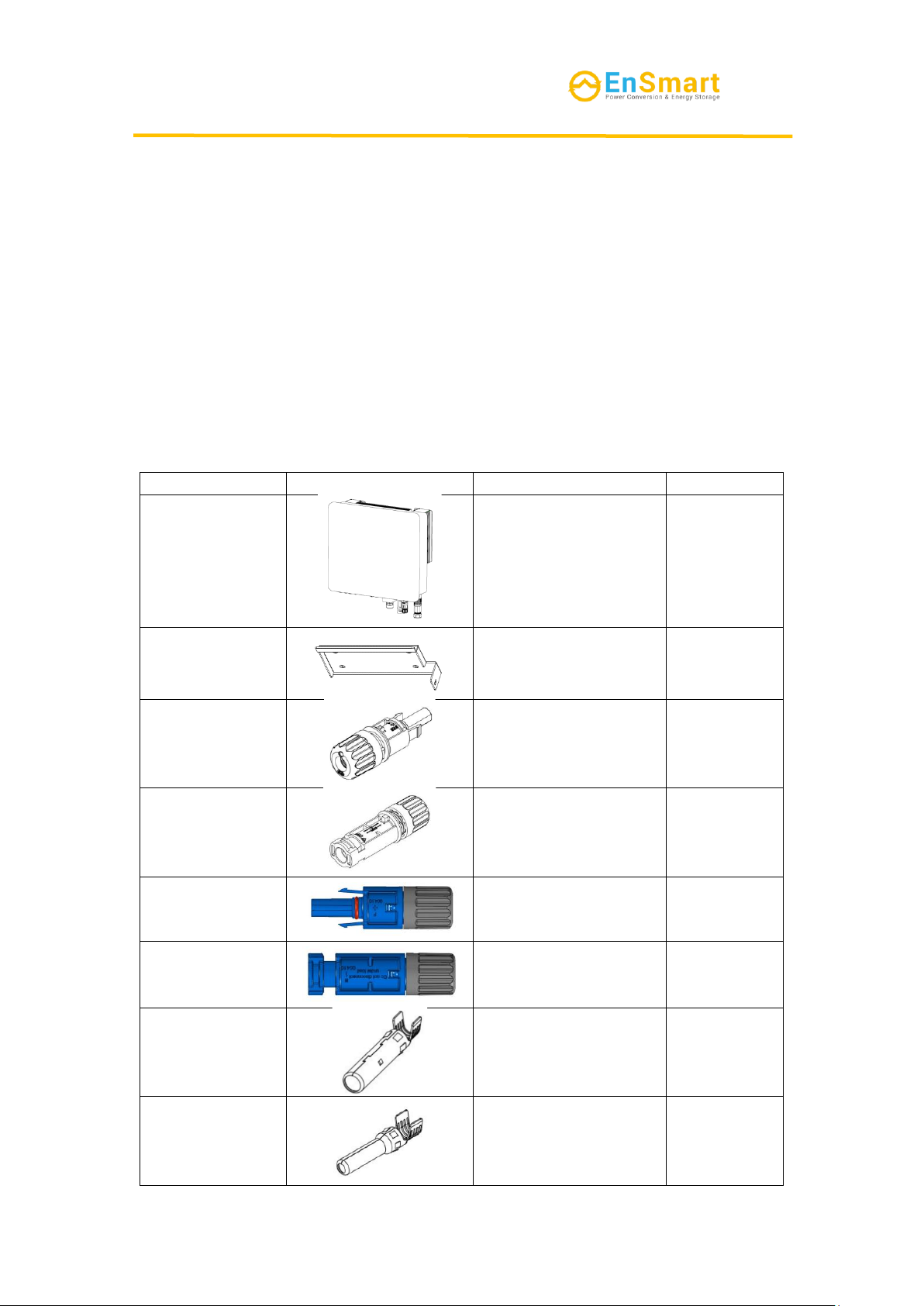
3.2 List of deliverables
Check the deliverables for completeness after unpacking the inverter and contact
your dealer if any components are found to be missing or incomplete.
Table 3-1 Components and mechanical parts to be delivered
Series No.
Picture
Description
Quantity
1
Inverter
1PC
2
Wall-mounted rear
cover
1PC
3
PV+ wire end input
terminal plastic case
4PCS
4
PV- wire end input
terminal plastic case
4PCS
5
BAT+ wire end input
terminal plastic case
2PCS
6
BAT- wire end input
terminal plastic case
2PCS
7
PV+ wire end input
terminal metal core
4PCS
8
PV- wire end input
terminal metal core
4PCS

SolarAll-H User Manual
7
9
BAT+ wire end input
terminal metal core
2PCS
10
BAT- wire end input
terminal metal core
2PCS
11
AC grid terminal
1PC
12
AC load terminal
1PC
13
M8*80 expansion bolt
4PCS
14
Cross recessed
hexagon head
combination screw
M6*20
1PC
15
Smart meter
1PC
16
CT
(used with the meter)
3PCS
17
BMS communication
line
1PC
18
DRMS communication
line
1PC

SolarAll-H User Manual
8
19
Parallel
communication line
1PC
20
WIFI acquisition bar
(optional)
1PC
21
User Manual
1PC
22
Warranty Card
1PC
23
Certificate of
Inspection
1PC
24
desiccant
1PC
3.3 Equipment storage
Please store the inverter according to the following requirements if it is not to be
put into use immediately:
1. Ensure that the outer packing box is not removed and the desiccant inside the
box is not lost.
2. Ensure that the storage environment is clean and the temperature and humidity
range is appropriate.
3. Ensure that the inverter stacking height and direction are placed in accordance
with the label instructions on the box.
4. Ensure that there is no risk of tipping of the inverters after stacking.
5. The inverter must be checked and confirmed by professional personnel before
it can be used again after long-term storage.
SolarAll-H User Manual
9
4. Product introduction
4.1 Product overview
Three phase hybrid inverter inverter is a three-phase PV energy storage inverter
that integrates grid-connected PV inverter and battery storage.
Three phase hybrid inverter inverter has a variety of built-in operating modes to
suit the diverse needs of users.
Three phase hybrid inverter inverter provides a complete solution in times of
rising energy costs such as oil and coal, declining energy subsidies for grid-connected
PV systems, mountainous areas or base stations without grid access, uninterrupted
power supply, and emergency power needs.
4.2 Application scenario
PV systems are not suitable for connection to equipment
that depends on a stable power supply, such as life-sustaining
medical equipment, etc. Please ensure that no personal injury is
caused when the system loses power.
Please avoid using loads with higher starting currents in
PV systems as much as possible, otherwise the off-grid output
may fail due to excessive instantaneous power.
The inverter can restart automatically when the inverter
overload protection occurs in a single time; if it happens several
times, the inverter restart time will be extended, and you can
restart the inverter immediately through the App if you need to
restart the inverter as soon as possible.
If the load capacity exceeds the rated power of the inverter
when the grid is down, the off-grid function of the inverter will
automatically shut down; if you want to start it, you need to turn
off the large load and make sure the load power is less than the
rated power of the inverter.
The inverter can be used for normal household loads when
it is in off-grid mode, e.g:
Inductive load: 1.5P non-inverter air conditioners can be
supported. Access to two or more non-inverter air conditioners
may lead to unstable standby mode.
Capacitive load: total power ≤ 0.66×inverter rated output
power.
4.3 Working mode
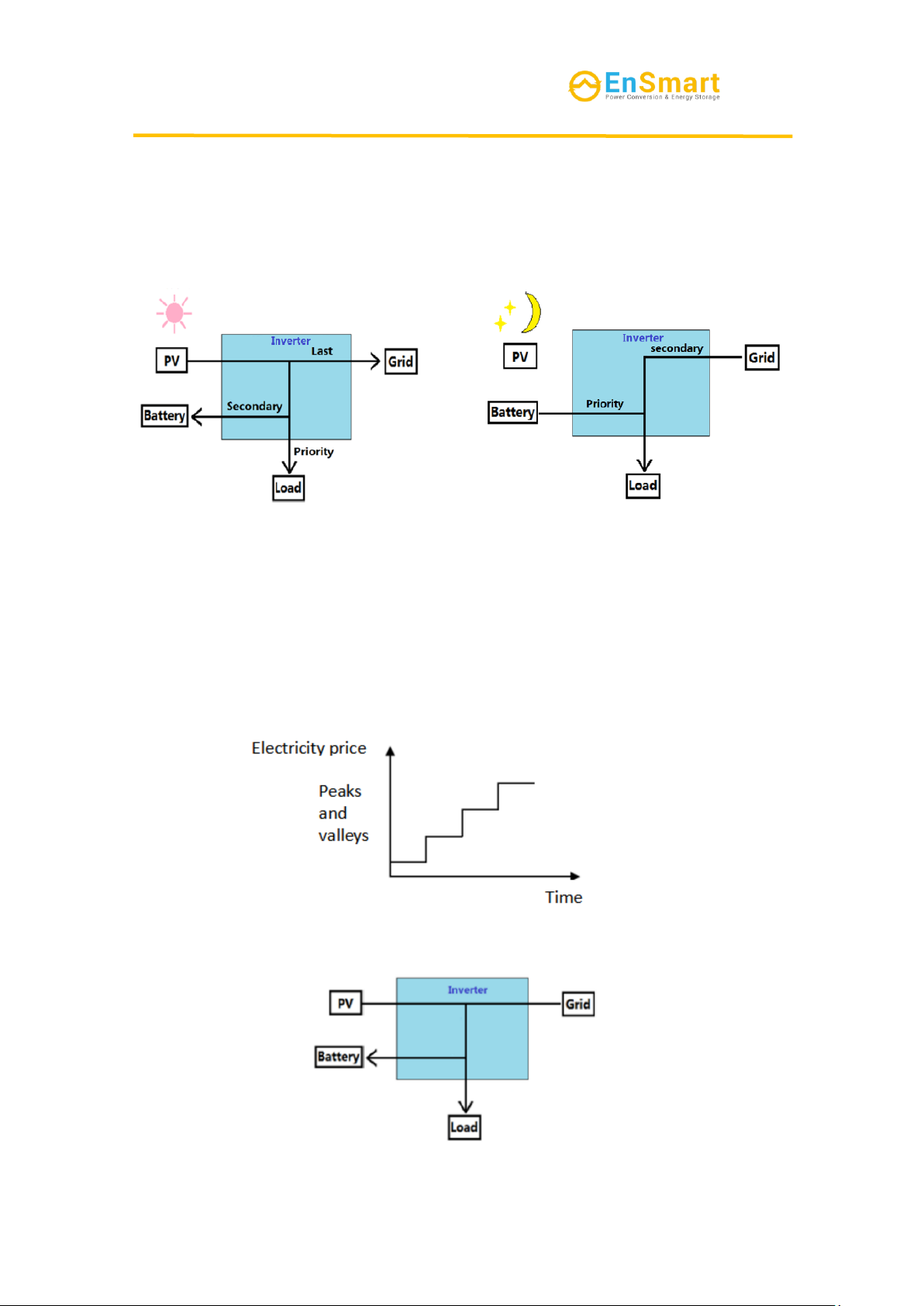
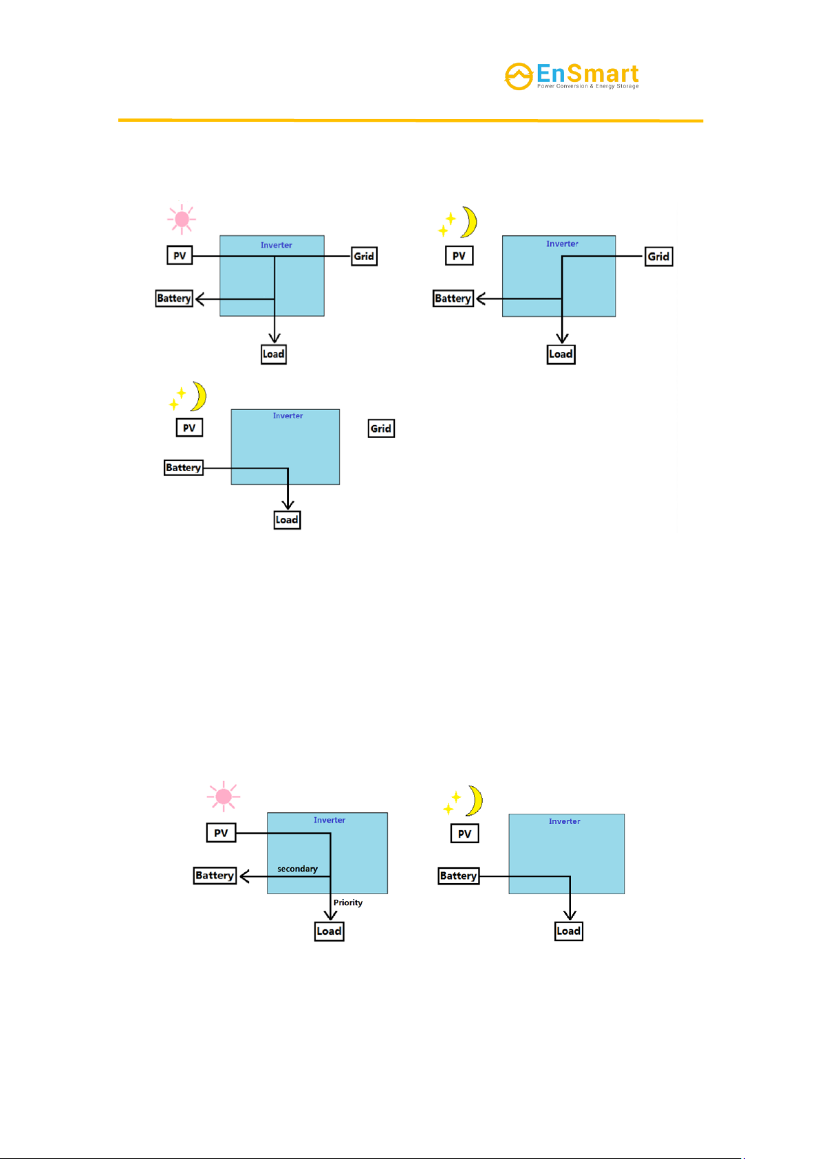
4.3.1 Self-generation and self-use mode
Functions:
Prioritizes the use of PV and battery energy, and does not use energy from the grid
as much as possible.
Specific working methods:
1.When PV is sufficient, PV prioritizes power supply to the load, then charges the
battery, and any remaining energy can be feed into the grid.
2.When PV is insufficient, the PV、battery and power grid jointly supply power
to the load.
SolarAll-H User Manual
10
3.When PV is not working, the battery and the grid work together to power the
load. (priority battery power the load)
Attention :the anti-reverse function is not enabled by default.
4.3.2 Time-of-use tariff mode
Functions:
Depending on the price of electricity at different times, during the valley period
the power grid and PV give priority to load power supply, and the remaining energy
charges the battery. The other period are spontaneous self-use mode.
Specific working methods:
During the valley time period: the grid and PV power the load first,and the
remaining energy charges the battery.
Valley time period:
Average time period

SolarAll-H User Manual
11
Peak time period:
4.3.3 Disaster Recovery Mode
Functions:
When the power grid is abnormal, the energy storage system will provide power
to the user separately. This mode can maintain power supply even when the user
encounters special situations such as abnormal power grid conditions. (The battery
requires a charging and discharging cycle every six months, which needs to be manually
set)
Specific working methods:
1. PV and the power grid jointly supply power to the battery and load.(PV
prioritizes charging the battery)
2. When the power grid is normal, the battery SOC remains fully charged.
3. The battery will only discharge when the power grid is abnormal.
Attention :the anti-reverse function is not enabled by default.
SolarAll-H User Manual
12
4.3.4 Off-grid Mode
Functions:
The PV and battery form an off grid system, and the inverter is used off the grid.
Specific working methods:
1. If the PV is sufficient, the PV prioritizes power supply to the load and excess
energy is used to charge the battery.
2. If the PV is insufficient, the PV and battery will supply power to the load.
3. If the PV does not work,the battery supplies power to the load.
4.3.5 Time charge and discharge mode
Functions:
Set the charging and discharging time according to the user’s need.
Specific working methods:

SolarAll-H User Manual
13
According to their own needs, the battery charge and discharge timing settings. if
the power failure notification is known in advance, the battery can be filled remotely in
advance for household load use.
4.4 Inverter operation mode
Table 4-1 Description of Inverter Operation Mode
Series
No.
Mode
Description
1
Wait mode
Waiting phase after the inverter is powered on.
Enter self-check mode when conditions are met.
If there is a fault, the inverter enters the fault mode.
2
Self-check
mode
The inverter continuously performs self-check,
initialization, etc. before starting up.
If the conditions are met, it enters grid-connected mode
and the inverter starts grid-connected operation.
If no grid is detected, it enters off-grid mode and the
inverter runs off-grid.
If the self-check is not passed, it enters fault mode.
3
Grid-connected
mode
The inverter operates normally in grid-connected.
If grid non-existence is detected or the grid conditions are
detected that do not meet the grid connection requirements, it
enters off-grid operation mode.
If a fault is detected, it enters fault mode..
4
Off-grid mode
When the grid is disconnected or the grid conditions are
detected that do not meet the grid connection requirements ,the
inverter working mode switches to off-grid mode to continue
to supply power to the load.
If the grid conditions are detected to meet the grid
connection requirements, it will enter the grid-connected mode.
If a fault is detected, it enters fault mode.
5
Fault mode
If a fault is detected, the inverter enters fault mode, waits
for the fault to clear, returns to the previous running mode.

SolarAll-H User Manual
14
4.5 Appearance description
4.5.1 Appearance introduction
Figure 4.1 Illustration of the appearance of the hybrid inverter
Table 4-2 Appearance of a hybrid inverter
1
PV DC input port (PV+/-)
2
PV DC input switch
3
Waterproof and breathable device
4
Battery DC input port (BAT+/-)
5
Communication module interface
6
WiFi/4G interface
7
Off-grid AC wiring port
8
Grid-connected AC wiring port
9
Fan assembly
10
Protective ground terminal
11
inductive cooling box
SolarAll-H User Manual
15
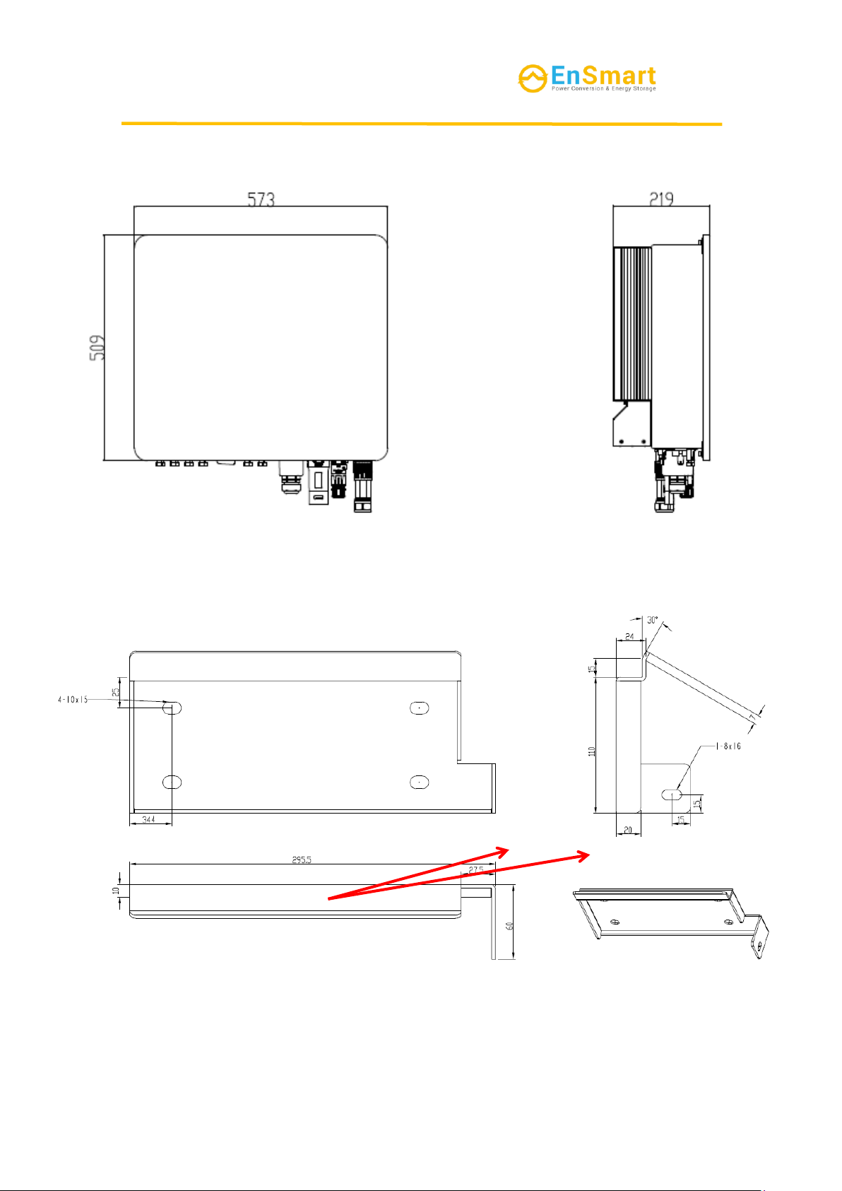
4.5.2 Dimensional description
Figure 4.2 hybrid inverter dimensions
Figure 4.3 Wall mounted component dimensions
4-9×12waist hole

SolarAll-H User Manual
16
5 Installation
5.1 Installation requirements
5.1.1 Installation environment requirements
1. The equipment shall not be installed in flammable, explosive or corrosive
environments.
2. The installation position shall avoid the water pipe and cable in the wall to avoid
the danger when drilling.
3. Installation location shall avoid the range of children's access, and avoid
installation in the easy-to-touch location. Please note that there may be high temperature
on the surface when the equipment is operating, so please be careful of burns.
4. The inverter shall avoid the installation environment of sun, rain and snow, etc.
It is recommended to be installed in a sheltered installation position, and if necessary,
a sunshade can be built.
5. The installation space shall meet the requirements of equipment ventilation and
heat dissipation and operation space.
6. The protection level of the equipment shall meet the indoor and outdoor
installation, and the temperature and humidity of the installation environment shall be
within the suitable range.
7. Please ensure that the equipment indicator and all labels can be easily viewed
and the terminals are easy to operate.
8. The installation altitude of the inverter shall be lower than the maximum
working altitude of 4000m.
9. Please keep away from strong magnetic field environment to avoid
electromagnetic interference. Please install the equipment in accordance with the
following requirements if there are radio stations or wireless communication equipment
below 30MHz near the installation location:
1) Add multi-turn winding ferrite cores at the DC input wire or AC output wire of
the inverter, or add low-pass EMI filters.
2) The distance between the inverter and the wireless EMI equipment shall exceed
30m.
5.1.2 Installation carrier requirements
1. The installation carrier shall not be flammable materials, and must have
fireproof performance.
2. Please ensure that the installation carrier is strong and reliable and can carry the
weight of the inverter.
3. Please do not install the inverter on a carrier with poor sound insulation, as the
noise from the operation of the equipment may cause disturbance to the residents in
the living area.
5.1.3 Installation angle requirements
1 .Recommended Installation angle of inverter: vertical or tilted back ≤ 15°.
2. The Inverter shall not be installed upside down, tilted forward, tilted back
beyond the angle, or horizontal.
This manual suits for next models
4
Table of contents
Popular Inverter manuals by other brands


Tsun
Tsun TSOL-M350 user manual

Fortress Power
Fortress Power FP-ENVY 12K Installation & user manual

Mastervolt
Mastervolt WHISPER 9.5 ULTRA installation manual

WELDING INDUSTRIES
WELDING INDUSTRIES 125i MC91-0 Operator's manual

Vector
Vector MAXX SST VEC049C owner's manual

HQ Power
HQ Power PSIC75 Series user manual