EnerWorks Thermal Energy User manual
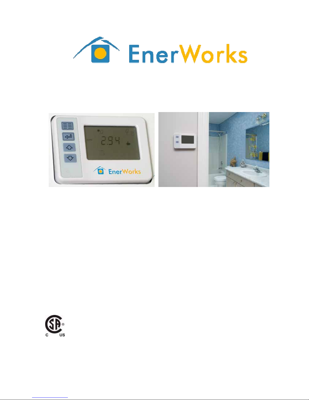
EnerWorks Solar Thermal Water Heating Appliances
Thermal Energy Controller and Thermal Energy Monitor
Owner Manual
EnerWorks Inc.
252 Hamilton Crescent
Dorchester, Ontario
N0L 1G4
Canada
Telephone: 519-268-6500
Toll-free: 1-877-268-6502
Fax: 519-268-6292
Web: www.enerworks.com
232023
FCC ID: VFC070501
IC: 7193A070501

This Class B digital apparatus complies with Canadian ICES-003.
Cet appareil numérique de la classe B est conforme à la norme NMB-003
du Canada.
FCC Information to Users @ FCC 15.105
For Class B Unintentional Radiators:
This equipment has been tested and found to comply with the limits for a Class
B digital device, pursuant to Part 15 of the FCC Rules. These limits are designed
to provide reasonable protection against harmful interference in a residential
installation. This equipment generates, uses, and can radiate radio frequency
energy and, if not installed and used in accordance with the instruction manual,
may cause harmful interference to radio communications. However, there is no
guarantee that interference will not occur in a particular installation. If this
equipment does cause harmful interference to radio or television reception,
which can be determined by turning the equipment off and on, the user is
encouraged to try to correct the interference by one of more of the following
measures:
Reorient or relocate the receiving antenna;
Increase the separation between the equipment and receiver;
Connect the equipment into an outlet on a circuit different from that to
which the receiver is connected;
Consult the dealer or an experienced radio/TV technician for help.
Warning to Users @ FCC 15.21
Warning: Changes or modifications not expressly approved by the party
responsible for compliance could void the user’s authority to operate the
equipment.
Warning: To satisfy FCC RF exposure requirements for mobile transmitting
devices, a separation distance of 20 cm or more should be maintained between
the antenna of this device and persons during device operation. To ensure
compliance, operations at closer than this distance is not recommended. The
antenna used for this transmitter must not be co-located in conjunction with any
other antenna or transmitter.
Part number: LAA300
Revision 1.0
2008,06,09
© EnerWorks Inc.
EnerWorks recommends using rechargeable
batteries to power your Thermal Energy Monitor.
Dispose of dead batteries in a responsible fashion
that is friendly to the environment.
Applies to the following models:
- TEC-001
- TEM-001
Components of the following appliances:
- High Performance
- Space-Saver™

i
TEC/TEM owner manual
Table of Contents
1.0 Introduction ................................................................................................1
2.0 Outputs menu..............................................................................................2
2.1 Savings displays ............................................................... 2
2.1.1 Economic savings ........................................................................... 3
2.1.2 Carbon dioxide offset ...................................................................... 3
2.1.3 Household hot water used ............................................................... 4
2.1.4 Water saved by displacing electricity generation .................................. 4
2.1.5 Solar energy delivered ........................................................................... 5
2.1.6 Auxiliary energy consumed – Space-Saver™Appliance ................................ 5
2.1.7 Equivalent energy offset for auxiliary fuel.................................................. 6
2.2 Readings displays ....................................................................................... 7
2.2.1 ∆T (temperature difference) ............................................... 7
2.2.2 Collector temperature .................................................................... 9
2.2.3 Storage temperature ...................................................................... 9
2.2.4 Maximum/minimum control temperatures ..................... 9
2.2.5 Temperature of cold-water supply from mains water .........................10
2.2.6 Temperature of hot-water outlet to household .................................11
2.2.7 Maximum/minimum energy temperatures ..........................11
2.2.8 Instantaneous power ............................................................................12
2.3 Time/date displays ..................................................... 13
3.0 Programming menu (Thermal Energy Controller) ............................14
3.1 Pump control ...................................................................... 14
3.2 Default units of measurement ..................................................................... 15
3.3 Auxiliary fuel ............................................................................................ 15
3.3.1 Fuel type ...................................................................15

ii
TEC/TEM owner manual
3.3.2 Units for auxiliary fuel .................................................16
3.3.3 Price of auxiliary fuel .......................................17
3.3.4 Generation mix of electricity .........................................................18
3.3.5 Water required for electricity generation .......................................19
4.0 Date/time menu (Thermal Energy Controller) .................................20
4.1 Setting up the system time/date .................................. 20
4.1.1 System time ..............................................................................20
4.1.2 System date ...................................................................21
4.2 Reset maximum/minimum values ........................................................ 21
4.3 Reset energy values ........................................................................... 22
4.4 Software version....................................................................................... 22
5.0 Programming mode (Thermal Energy Monitor) ..........................23
6.0 Icon reference...........................................................................................24
7.0 Error codes................................................................................................28
Disclaimer: All examples are only for demonstration purposes and do not
necessarily reflect actual performance of your appliance.

1/34
TEC/TEM owner manual
1.0 Introduction
The EnerWorks Thermal Energy Controller and Thermal Energy Monitor
work together to display how much money, energy, and carbon dioxide you are
saving by installing an EnerWorks Solar Water Heating Appliance. Your
commitment to the environment is now demonstrable – you can be green and
show it off, too!
The Thermal Energy Controller is a control unit that is integrated into the
Energy Pack, performing control functions while also monitoring performance.
Using wireless transmission, the Thermal Energy Controller sends information to
the Thermal Energy Monitor. The Thermal Energy Monitor then displays these
data so that you can observe the performance of the system from anywhere in
your home.
So that a household is never without hot water, a backup or “auxiliary”
tank must be in place in case there is not enough solar energy to meet the
demand of the household. The four major fuels for water-heating in North
America are electricity, natural gas, propane, and oil.
Thermal Energy Controller Thermal Energy Monitor
Energy Pack mounted on a solar storage tank

2/34
TEC/TEM owner manual
2.0 Outputs menu
The Thermal Energy Monitor displays the outputs menu. This is
the view that shows your savings in money, energy, carbon dioxide,
etc., and is the default view on the Thermal Energy Controller (located
on the Energy Pack). Pressing the up and down buttons on either unit
scrolls through the displays. On the Thermal Energy Controller,
pressing and holding the enter button for five seconds will set the
current display item as the default display item.
The Thermal Energy Monitor will turn off its screen after three
minutes of inactivity.
2.1 Savings displays
Each value in this section displays information for a certain time interval:
indicates current reading is for today (since midnight).
indicates reading is for this month (from first of month).
indicates reading is for this year (as of January 1).
(sigma) indicates reading is cumulative date of commissioning.
Enter button
Up button
Down button

3/34
TEC/TEM owner manual
Fi
g
ure 2.1.2
Fi
g
ure 2.1.1
2.1.1 Economic savings
Default display is “cumulative money
saved”. Below is an example of the
display (see figure 2.1.1). The sigma
symbol ( ) indicates “cumulative”,
meaning that the value being displayed
is the total from the time that the
appliance was commissioned. The
piggy bank ( ) indicates money
savings. The value ($392.8 in figure
2.1.1) is the amount saved to date,
based on the amount of energy delivered by the appliance multiplied by the fuel
rate for the auxiliary water tank (see section 3.3.3). Press the down button to
view the money savings for other time periods.
2.1.2 Carbon dioxide offset
Pressing the up button from
cumulative money saved will display
“daily carbon dioxide offset” (see figure
2.1.2). This is the amount of carbon
dioxide (CO2) – in tonnes or tons,
depending on units of measure chosen
(see section 3.2) – not emitted into the
atmosphere because the water was
heated by solar energy instead of a
fossil fuel. Your pre-existing or previous
water heater uses/used fossil fuels or
electricity (which is normally generated
using a mix of fossil fuels) to heat water.
CO2is produced by burning fossil fuels. The CO2value is based on the
amount of energy produced by the appliance and the fuel type for the auxiliary
water tank (see section 3.3.4), and represents the amount of CO2emissions
prevented by displacing the burning of fossil fuels. Figure 2.1.2 is an example of
what the screen looks like (using tonnes as the unit of measurement) after a
day’s worth of energy is produced by the system.
Pressing the up button again will show monthly ( ) carbon dioxide
offset; press again for yearly ( ), and once more for cumulative ( ).

4/34
TEC/TEM owner manual
Fi
g
ure 2.1.3
Fi
g
ure 2.1.4
2.1.3 Household hot water used
Pressing the up button from
cumulative carbon dioxide offset will
display “daily household hot water used”
(see figure 2.1.3). This is the volume –
in US gallons or litres, depending on
units of measure chosen (see section
3.2) – drawn for domestic hot water use
as read by the flow sensor on the cold-
water supply from mains. Figure 2.1.3
is an example of a reading (using US
gallons as the unit of measurement).
Pressing the up button again will show monthly ( ) household hot
water used; press again for yearly ( ), and once more for cumulative ( ).
2.1.4 Water saved by displacing electricity generation
Pressing the up button from
cumulative water used will display either
“instantaneous power” (see section
2.2.8) or “daily water saved by
displacing electricity generation” (see
figure 2.1.4). Water saved by displacing
electricity generation is only available
when the fuel for the auxiliary water
heater is electricity, and will show before
instantaneous power. It can be
displayed in US gallons or litres,
depending on units of measure chosen
(see section 3.2).
The production of electricity requires water (see section 3.3.5). As fresh
water resources become more scarce and sensitive, it is important to use water
wisely, including directing it away from electricity generation. Water saved by
displacing electricity generation is the volume of water that is not used because
of the amount of electricity that is offset by the EnerWorks hot-water appliance.
Figure 2.1.4 is an example of a reading (using litres as the unit of
measurement).

5/34
TEC/TEM owner manual
Fi
g
ure 2.1.5
Fi
g
ure 2.1.6
Pressing the up button again will show monthly ( ) water saved by
displacing electricity generation; press again for yearly ( ), and once more
for cumulative ( ). Pressing up from the cumulative value will display
instantaneous power (see section 2.2.8).
2.1.5 Solar energy delivered
Pressing the up button from
minimum hot-outlet temperature (see
section 2.2.7) will show “daily energy
delivered”, which is the amount of solar
energy delivered by the EnerWorks
appliance today (see figure 2.1.5).
Energy production is based on the
amount of power (see section 2.2.8)
generated over a period of time, given
in units of thermal Watt-hours (Whth).
For simplification, the display truncates
the “th” subscript. Figure 2.1.5 is an example of a daily delivery, 8 219 Wh (or
8.219 kWh).
Pressing the up button again will show monthly ( ) solar energy
delivered; press again for yearly ( ), and once more for cumulative ( ).
2.1.6 Auxiliary energy consumed – Space-Saver™Appliance
Pressing the up button from
cumulative energy produced (see
section 2.1.5) will display “daily
equivalent energy offset for auxiliary
fuel” (see section 2.1.7) for the
EnerWorks High Performance Appliance.
Since the EnerWorks Space-Saver™
Appliance uses electricity within the
same tank as the solar storage, the
Thermal Energy Controller and Thermal
Energy Monitor for these single-tank
appliances will show “daily auxiliary

6/34
TEC/TEM owner manual
Fi
g
ure 2.1.7
energy consumed” first (see figure 2.1.6) with equivalent energy offset for
auxiliary fuel following.
In the Space-Saver™ appliance, the water is heated by both solar and an
auxiliary fuel source (electricity). The Thermal Energy Controller monitors the
thermal energy produced by solar and the electric energy consumed by the
appliance. Energy used is based on the amount of power consumed over a
period of time, given in the units of Watt-hours (Wh).
The power delivered to the heating element in the tank will not be
constant; however, the Thermal Energy Controller must assume that the power
supply is constant because it does not have a power meter hooked up to it.
Thus, an average power consumption by the heating element is assumed and is
set upon installation. The electric energy for the heating element is deducted
from the total energy delivered by the Space-Saver™ in order to show the
amount of solar energy delivered.
Figure 2.1.6 is an example of a daily electricity consumption, 2 739 Wh
(or 2.739 kWh). The lightning bolt ( ) – representing electricity as the
auxiliary fuel – blinks on this screen, indicating that it is showing the amount of
energy consumed by the heating element.
Pressing the up button again will show monthly ( ) auxiliary energy
consumed; press again for yearly ( ), and once more for cumulative ( ).
Pressing up from the cumulative value will display daily equivalent energy offset
for auxiliary fuel (see section 2.1.7).
2.1.7 Equivalent energy offset for auxiliary fuel
Pressing the up button from
cumulative energy produced (see
section 2.1.5) will display “daily
equivalent energy offset for auxiliary
fuel” on the EnerWorks High
Performance Appliance (see figure
2.1.7). Since the EnerWorks Space-
Saver™ Appliance uses electricity within
the same tank as the solar storage, the
Thermal Energy Controller on these
single-tank appliances will show “daily
auxiliary energy consumed” first (see
section 2.1.6) with the daily equivalent energy offset for auxiliary fuel following.

7/34
TEC/TEM owner manual
Fi
g
ure 2.2.1a
Depending on the auxiliary fuel type, this screen will show how much of
that fuel has been offset by solar. The four possible fuel types for a High
Performance Appliance are electricity, natural gas, propane, and oil. The Space-
Saver™ Appliance can only be supplemented with electricity.
For example, if the daily production from solar is 8219 Wh, then the daily
amount of electricity saved will also be 8219 Wh (see figure 2.1.7). The
lightning bolt ( ) – representing electricity as the auxiliary fuel – does not
blink on this screen, indicating that it is showing the fuel-equivalent amount of
energy offset by solar. This value is under-represented for a High
Performance Appliance since the calculations can not include the efficiency of
the auxiliary water heater.
Pressing the up button again will show monthly ( ) equivalent energy
offset for auxiliary fuel; press again for yearly ( ), and once more for
cumulative ( ). Up from cumulative shows “daily money saved” (see section
2.1.1).
2.2 Readings displays
The readings that follow show the status of the EnerWorks appliance.
2.2.1 ∆T (temperature difference)
The ∆T (“delta-T”) value is the
temperature difference between the
solar collector (see section 2.2.2) and
the temperature at the bottom of the
storage tank (see section 2.2.3). When
this difference reaches 10 °C (18 °F),
the appliance will begin to collect solar
energy.
Figure 2.2.1a is an example of
when the system would be operating
with ample solar energy, indicated by
the sun shining on the solar collector ( ).

8/34
TEC/TEM owner manual
Fi
g
ure 2.2.1b
Note: the sun does not mean that the actual weather is sunny, just that
there is enough solar energy for energy collection. Even on an overcast day, an
EnerWorks appliance can collect energy.
Should the difference drop below
5 °C (9 °F), the appliance will turn off
until the difference reaches 10 °C (18
°F).
Figure 2.2.1b is an example of the
system turned off because there is not
enough solar energy, indicated by the
cloud with the solar collector ( ).
Note: the cloud does not mean that the actual weather is cloudy, just
that there is not enough solar energy for energy collection.
Pressing the up button will display the temperature of the collector (see
section 2.2.2).

9/34
TEC/TEM owner manual
Fi
g
ure 2.2.2
Fi
g
ure 2.2.3
2.2.2 Collector temperature
The collector temperature is
measured by a temperature sensor
installed in one of the solar collectors.
It is used with the storage temperature
(see section 2.2.3) to determine ∆T (see
section 2.2.1). In the example, the
reading is 154 °F.
Pressing the up button will display
the temperature of the water at the
bottom of the solar storage tank (see
section 2.2.3).
2.2.3 Storage temperature
The storage temperature is
measured at the bottom of the solar
storage tank. It is used with the
collector temperature (see section
2.2.2) to determine ∆T (see section
2.2.1). In the example, the reading is
31 °C.
Pressing the up button will display
the maximum collector temperature.
2.2.4 Maximum/minimum control temperatures
For collector and storage temperatures, the historical maxima and minima
are stored in memory. These values are for informational purposes (interest,
maintenance, etc.) and are not used in any calculations. The recorded values
can be cleared using the reset function (see section 3.4).
From “storage temperature”, pressing the up button shows “maximum
collector temperature”, followed by “minimum collector temperature”, then
“maximum storage temperature”, and finally “minimum storage temperature”.

10/34
TEC/TEM owner manual
Fi
g
ure 2.2.5
The four following screens show examples of readouts (max. collector 193 °F,
min. collector 40 °F, max. storage 57 °C, min. storage 11 °C).
Figure 2.2.4a Figure 2.2.4b
Figure 2.2.4c Figure 2.2.4d
Pressing the up button from minimum storage temperature displays the
current reading of the temperature of the cold-water supply from mains.
2.2.5 Temperature of cold-water supply from mains water
The flow sensor on the mains
water inlet also contains a temperature
sensor. This temperature and the
temperature of the hot water being
delivered (see section 2.2.6) are used
for calculating energy production. An
example of the mains reading can be
seen in figure 2.2.5 (reading 14 °C).
Pressing the up button moves on
to the hot-outlet temperature.

11/34
TEC/TEM owner manual
Fi
g
ure 2.2.6
2.2.6 Temperature of hot-water outlet to household
A temperature sensor mounted on
the hot-water outlet from the tank
measures this temperature. This
temperature and the temperature of the
cold-water supply from mains (see
section 2.2.5) are used for calculating
energy production. An example of the
hot-outlet reading can be seen in figure
2.2.6 (reading 62 °C).
Pressing the up button will display
the maximum temperature of cold-water
supply from mains.
2.2.7 Maximum/minimum energy temperatures
For the mains and hot-outlet temperatures, the historical maxima and
minima are stored in memory. These values are for informational purposes
(interest, maintenance, etc.) and are not used in any calculations. The recorded
values can be cleared using the reset function (see section 3.4).
From “hot-outlet temperature”, pressing the up button shows “maximum
temperature of cold-water supply from mains”, followed by “minimum
temperature of cold-water supply from mains”, then “maximum temperature of
hot-water outlet to household”, and finally “minimum temperature of hot-water
outlet to household”. The four following screens show examples of readouts
(max. mains 30 °C, min. mains 7 °C, max. hot 67 °C, min. hot 48 °C).
Figure 2.2.7a Figure 2.2.7b

12/34
TEC/TEM owner manual
Fi
g
ure 2.2.8
Figure 2.2.7c Figure 2.2.7d
Pressing the up button from minimum hot-outlet temperature will go to
the current reading of the daily solar energy delivered (see 2.1.5).
2.2.8 Instantaneous power
Pressing the up button from
cumulative household hot water used
(see section 2.1.3) will display either
“instantaneous power” or “daily water
saved by displacing electricity
generation” (see section 2.1.4). Water
saved by displacing electricity
generation is only available when the
fuel for the auxiliary water heater is
electricity, and will show before
instantaneous power.
Instantaneous power is read when there is a draw of hot water in the
household. The amount of power being produced by the EnerWorks appliance is
determined by a formula that uses the volume of water, the cold-inlet
temperature (mains water) (see section 2.2.5), and the hot-outlet temperature
(hot water to the auxiliary tank in a High Performance appliance; hot water to
domestic use in Space-Saver™ appliance) (see section 2.2.6). As power is
accumulated over a time period, it is converted into an energy value.
Figure 2.2.8 is an example of a reading when there is a hot-water draw in
the household.
Pressing the up button again will move on to time and date (see section
2.3).

13/34
TEC/TEM owner manual
Fi
g
ure 2.3a
2.3 Time/date displays
Pressing the up button from
instantaneous power will display the
current time. The screen in figure 2.3a
is showing twelve o’clock (noon).
Pressing the up button from the
time will show the current year, then the
current month, and finally the current
day. The three screens below show
each of the three (March 14, 2008):
Figure 2.3b Figure 2.3c Figure 2.3d
Pressing the up button from the day will go into temperature information,
starting with the “delta-T value” (see section 2.2.1).

14/34
TEC/TEM owner manual
Fi
g
ure 3.1
3.0 Programming menu (Thermal Energy Controller)
There are a number of settings that may need to be changed from
time to time, such as the price of your auxiliary heating fuel or the type of
units that are displayed on screen. These settings can be changed by
using the programming menu on the Thermal Energy Controller.
To get to the programming menu, press the menu button from any
display on the outputs menu. The icon will light up to indicate that
you are in the programming mode. Pressing the menu button again from
any display will return to the outputs menu and will not save the changes
for the current item. Use the up and down buttons to toggle values, and
press the enter button to accept the value for the current item and move
to the next item.
Note that the status of the system will not be displayed while in
programming mode.
3.1 Pump control
The default mode for the pump is
to run automatically based on
temperature readings. If there is a
temperature difference of 18 °F (10 °C)
between the collector and the storage
tank, and none of the temperatures are
out of operating range, then the pump
will run.
A pump set to run manually will
run for fifteen minutes before reverting
back to automatic mode. A pump
turned off manually will not turn back on unless the setting is returned to
automatic or it is manually turned on.
Pressing the up or down button will cycle between automatic ( ) and
manual ( ). If automatic is selected, the menu moves on to the next item.
If manual is selected, pressing the up or down button will toggle between the
and the symbols, representing “on” and “off” respectively. The
diagram in figure 3.1 shows all of the segments that are visible for pump
control.
Menu
button
Up button
Down button
Enter button

15/34
TEC/TEM owner manual
Pressing the enter button will proceed to setting up the default units of
measurement.
3.2 Default units of measurement
There are two choices for default units: US customary and metric (SI).
This will affect all outputs and inputs on the controller, so if you already have
your settings the way you like them, you can select “n.c.” (no change) and the
defaults will not be restored. The default will display “S.I.” on the screen, and
pressing the up or down button will cycle between this, “U.S.”, and “n.c.”. Press
the enter button to accept and move on to fuel selection for the auxiliary heating
source.
As the inputs that follow are configured, the units can be changed to
whichever is preferred if “no change” wasn’t selected.
3.3 Auxiliary fuel
So that a household is never without hot water, a backup or “auxiliary”
tank must be in place in case there is not enough solar energy to meet the hot
water demand of the household. The four major fuels for water-heating in North
America are electricity, natural gas, propane, and oil.
3.3.1 Fuel type
There are four fuels available to select from for the auxiliary heating fuel:
electricity, natural gas, propane, and oil, represented by the icons above,
respectively. All four are available for the EnerWorks High Performance
Appliance, but only electricity is available for the Space-Saver™ Appliance.
The default fuel is electricity. For the High Performance Appliance, the up
or down button will toggle between the four icons along with the associated
default units. These units are likely used for billing purposes by the utility that
supplies the fuel.
The defaults units are:
kWh for electricity
m³ or 1000 ft³ for natural gas
L or US gal for propane and oil

16/34
TEC/TEM owner manual
Figure 3.3.1a Figure 3.3.1b
Figure 3.3.1c Figure 3.3.1d
Pressing enter will select the fuel type. The next screen allows you to
select a different billing unit if required.
3.3.2 Units for auxiliary fuel
Although there are default units for the fuel type, the following are
available for each fuel type:
Electricity: kWh, MMBTU
Natural gas: m³, 1000 ft³, GJ, MMBTU
Propane/Oil: L, US gal
In order to convert therms (100 000 BTU) into MMBTU (1 000 000 BTU),
multiply by 10. Example: $1.00/therm = $10.00/MMBTU.
To convert therms into 1000 ft³ (10 000 BTU), divide by 10. Example:
$1.00/therm = $0.10/1000 ft³.
Table of contents
Popular Water Heater manuals by other brands

Kardia
Kardia Standard V.102 user manual

emmeti
emmeti Comfort S Series Installation and use manual

Thermor
Thermor VM 050 D400S-3E instruction manual

Suburban
Suburban SW4P Installation and operation manual

Dimplex
Dimplex Ec-eau Installation and user instructions

Whirlpool
Whirlpool Residential Electric Water Heater Installation Instructions and Use & Care Guide

proTough
proTough NR111-DV installation manual

Sears
Sears Kenmore 153.576300 Use & care guide

Haier
Haier ES50H-T1 (E) operating instructions

Steinbach
Steinbach Solar Collector Deluxe owner's manual

Wijas
Wijas PERFECT 7000 Assembly and operation manual

STIEBEL ELTRON
STIEBEL ELTRON SHU 10 SLi comfort Operation and installation