6 - Installation and Commissioning
Installation must meet valid rules and may be done only by qualified staff. The tank shall be placed on the
floor, as close to the heat source as possible.
Defects caused by improper installation, use or handling are not covered by warranty.
6.1 - Connection to heat sources
Connect heating circuits to the inlets to and outlets from heating coils. The heat source for the tank - an enam-
eled coil - connects with G 5/4” couplings.
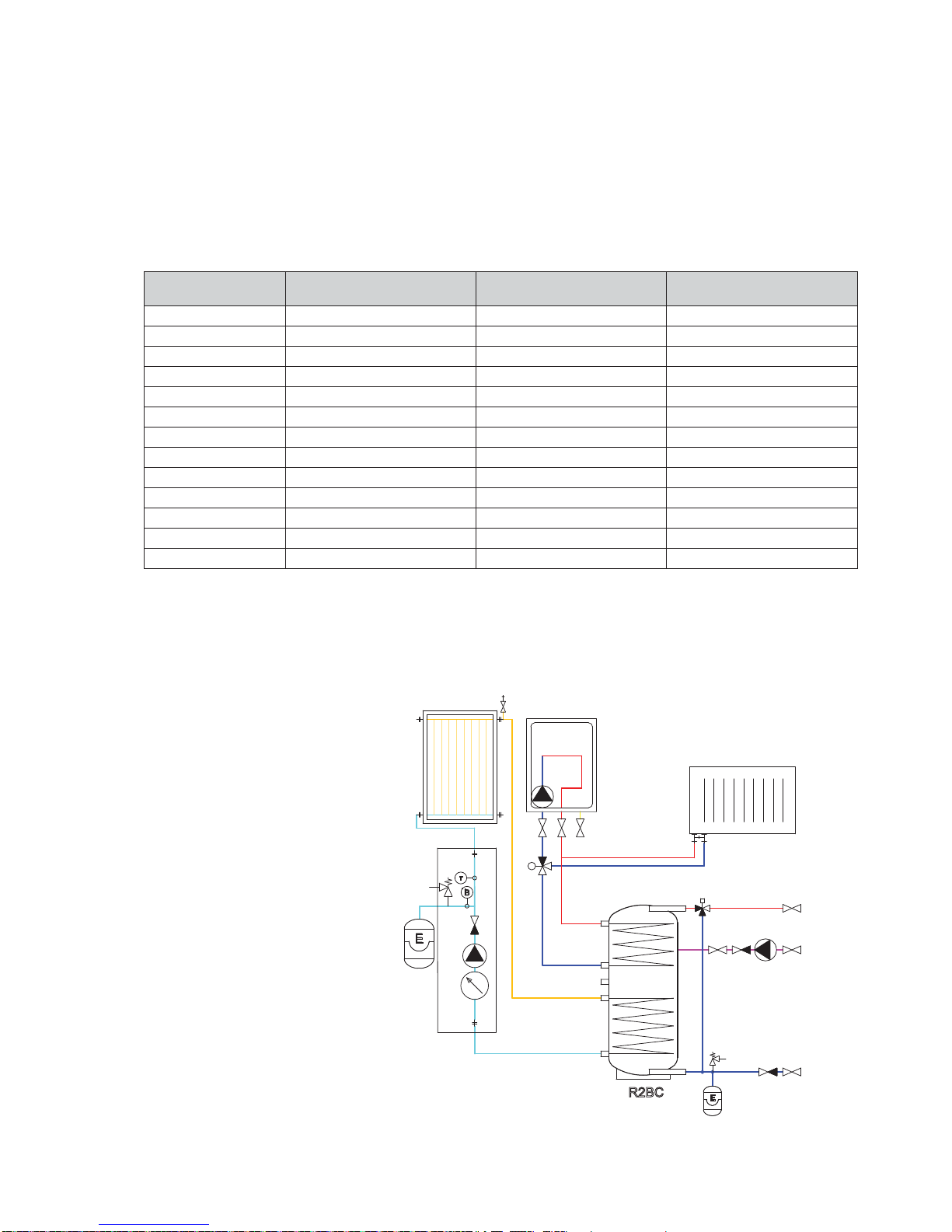
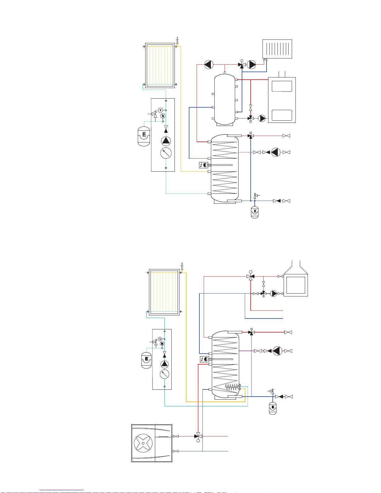
6.2 - Connection to a solar system
The tank can be used with a solar system. In such a case, the inlet for hot heat-carrying liquid coming from the
solar system shall be connected to the upper sleeve of the G 5/4” heating coil and the lower outlet to the return
piping to the solar system. Insulate all the piping between the tank and the solar system.
6.3 - Heating rod installation
The G 6/4“ side sleeve is designed to accommodate an electric heating rod. Heating rods of output up to 12
kW can be used (depending on the tank diameter and rod length), connected either directly to the mains (ther-
mostat-equipped rods), or to a heating system controller. The installation may be done by qualified staff only.
Warning: Electric heating elements shall be protected by a safety thermostat.
6.4 - Connection to water mains
DHW piping shall be done according to valid rules. G 5/4” threaded couplers are used to connect the tank to
a cold water inlet and hot water outlet. A 6bar safety valve shall be installed at the cold water inlet. Installation
of a reducing valve to the tank inlet is recommended. If the pressure from water mains exceeds 6 bar, a reduc-
ing valve is necessary. In order to prevent water loss, an expansion tank should be installed at the cold water
inlet as well (8 l volume for R2BC 200, 12 l volume for R2BC 300 and 400, 18 l volume for R2BC 500, 24 l vol-
ume for R2BC 750, 35 l volume for R2BC 1000, 60 l volume for R2BC 1500, 80 l volume for R2BC 2000, 100 l
volume for R2BC 2500 and 2×60 l volume for R2BC 3000).
Should the water be too hard, install a water softener before the tank. In case the water contains mechanical
impurities, install a strainer.
A suitable thermostatic mixing valve should be installed at the hot-water outlet from the tank, preventing too
hot water from entering the taps.
Install a drain valve to the lowest point of the tank.
Complete DHW piping shall be properly insulated.
6.5 - Electronic anode rod installation
A so called electronic anode can be used instead of the magnesium one. Its principle advantage is that its
proper function is signaled by a control lamp while a magnesium anode rod needs to be taken out for check. In
such a case, just visual check of the indication lamp of the electronic anode is sufficient.
Please use a G 5/4” to G ½” reducing coupler when installing an electronic anode. A space equal to the anode
length (see the table below) is needed between the tank top and ceiling to install/exchange the electronic an-
ode rod. In order to protect the tank properly and meet its warranty conditions, select an anode from the table
below.
Kit for R2BC storage water heaters
Code Anode rod length [mm] For storage water heaters
9173 350 (200/150) R2BC 200
9174 500 (350/150) R2BC 300, R2BC 400, R2BC 500
9175 750 (550/200) R2BC 750, R2BC 1000
Table of limit values for total dissolved solids in hot water
Description pH Total dissolved
solids (TDS)
Ca Chlorides Mg Na Fe
Max. value 6.5 - 9.5 600 mg/l 40 mg/l 100 mg/l 20 mg/l 200 mg/l 0,2 mg/l


 null")
 null")


 Operation and maintenance instructions")