Engbo MAXI 31 Operating manual
ENGBO AS –et selskap i Engbo-gruppen
BESØKSADRESSE: Wirgenesvei 7, 3157 Barkåker POSTADR: Postboks 2288 Postterminalen, 3103 Tønsberg
E-MAIL: suppo[email protected]o WEB: www.engbo.no TLF: +47 33 00 31 50 FAKS: +47 33 00 31 60
USER AND INSTALLATION
MANUAL
ENGBO ANCHOR WINCH
MAXI 31
MAXI 32
MAXI 34-series
MAXI 38
MAXI 40
Engbo MAXI products fit most boat models
Rev. 7-2010-01-04
According to NS-EN ISO 9001:2000
FCC ID: R78-RC-01
Part no. 117-00036 R78-MCU-01

ENGBO AS –et selskap i Engbo-gruppen
BESØKSADRESSE: Wirgenesvei 7, 3157 Barkåker POSTADR: Postboks 2288 Postterminalen, 3103 Tønsberg
E-MAIL: suppo[email protected] WEB: www.engbo.no TLF: +47 33 00 31 50 FAKS: +47 33 00 31 60
2
INNHOLD
INTRODUCTION......................................................................................................................................................... 3
GENERAL PROCEDURES FOR USING ENGBO MAXI WINDLASSES................................................................................ 4
OPERATING INSTRUCTIONS....................................................................................................................................... 5
Anchor down............................................................................................................................................................ 7
Anchor up................................................................................................................................................................. 7
The “Power” indicator information: ........................................................................................................................ 7
Forced operation of the windlass ............................................................................................................................ 7
A BRIEF DESCRIPTION OF THE ENGBO ANCHOR SYSTEM ........................................................................................... 8
ELECTRONIC CONTROL UNIT................................................................................................................................................. 8
SWITCH PANELS ................................................................................................................................................................ 9
Standard touch panel .............................................................................................................................................. 9
Wireless remote control .......................................................................................................................................... 9
Holder for wireless remote control ........................................................................................................................ 10
INSTALLATION –GENERAL....................................................................................................................................... 10
The anchor bracket................................................................................................................................................ 10
Hull conduit / Line guide ........................................................................................................................................ 11
Anchor rope ........................................................................................................................................................... 11
Safety line .............................................................................................................................................................. 12
Auto stop ............................................................................................................................................................... 12
WIRELESS REMOTE.................................................................................................................................................. 12
FITTING ANTENNA ........................................................................................................................................................... 12
CODING OF THE WIRELESS REMOTE CONTROL ........................................................................................................ 13
Procedure for wireless remote controls with serial no. above 8600...................................................................... 13
How to put the wireless control unit in code mode: .............................................................................................. 13
How to put the receiver unit in code mode:........................................................................................................... 13
DIMENSIONAL SKETCHES ........................................................................................................................................ 14
MAXI 31/40 –SERIES...................................................................................................................................................... 14
MAXI 32 –SERIES ........................................................................................................................................................... 14
MAXI 33 –SERIES ........................................................................................................................................................... 15
MAXI 34-SERIES ............................................................................................................................................................. 15
MAXI 38-SERIES ............................................................................................................................................................. 15
TECHNICAL SPECIFICATIONS.................................................................................................................................... 16
ELECTRICAL WIRING ................................................................................................................................................ 17
SWITCH PANEL................................................................................................................................................................ 17
Standard touch panel (Item no. 12-79000) ................................................................................................. 17
Connecting the switch panel.................................................................................................................................. 17
Connecting the auto stop switch ........................................................................................................................... 18
Connecting the motor and battery cables ............................................................................................................. 18
BATTERY CONNECTION ..................................................................................................................................................... 19
Main power switch ................................................................................................................................................ 19
Fuse and fuse holder.............................................................................................................................................. 19
ELECTRICAL WIRING DIAGRAM ............................................................................................................................... 20
FITTING INSTRUCTIONS ........................................................................................................................................... 21
GENERAL INFORMATION............................................................................................................................................ 21
Hinged platform roller ........................................................................................................................................... 21
Line guide in the stern........................................................................................................................................... 21
FITTING MAXI 31............................................................................................................................................................ 23

ENGBO AS –et selskap i Engbo-gruppen
BESØKSADRESSE: Wirgenesvei 7, 3157 Barkåker POSTADR: Postboks 2288 Postterminalen, 3103 Tønsberg
E-MAIL: suppo[email protected] WEB: www.engbo.no TLF: +47 33 00 31 50 FAKS: +47 33 00 31 60
3
FITTING MAXI 32............................................................................................................................................................ 23
Maxi 32 box ........................................................................................................................................................... 24
FITTING MAXI 33............................................................................................................................................................ 25
FITTING MAXI 40............................................................................................................................................................ 26
FITTING MAXI 34-V ........................................................................................................................................................ 27
FITTING MAXI 34-D ........................................................................................................................................................ 28
FITTING MAXI 34-G ........................................................................................................................................................ 29
Drawing - Maxi 34-G –line wheel, rope guide, rope guard and fixing plate ......................................................... 30
FITTING MAXI 34-S ......................................................................................................................................................... 31
FITTING MAXI 34-H ........................................................................................................................................................ 32
FITTING MAXI 38............................................................................................................................................................ 33
AUTO STOP FUNCTION...................................................................................................................................................... 34
Adjust the auto stop switch ................................................................................................................................... 34
Auto stop –fitting the stop indicator/brass wire................................................................................................... 34
MAINTENANCE........................................................................................................................................................ 36
Replacing the batteries in the wireless remote control ......................................................................................... 36
Replacing the line wheels ...................................................................................................................................... 37
Line guide –adjusting the tension spring .............................................................................................................. 38
Winter storage....................................................................................................................................................... 38
Troubleshooting..................................................................................................................................................... 39
INSTALLATION OF EQUIPMENT WITH HIGH CURRENTS - SPECIAL CONSIDERATIONS............................................... 40
Preface/introduction.............................................................................................................................................. 40
Battery ................................................................................................................................................................... 40
Battery-cables/lugs................................................................................................................................................ 41
Battery connection ................................................................................................................................................ 41
Fuse connection ..................................................................................................................................................... 41
Main switch connection......................................................................................................................................... 42
Control box connections ........................................................................................................................................ 42
Motor terminal connections .................................................................................................................................. 43
Introduction
Thank you for buying an Engbo anchor windlass. We hope you will find it useful and simple to
work with. To ensure that you do, it is essential that you fit and use it in accordance with the
instructions in this manual to ensure the best possible conditions for optimal windlass
operation. For example, the windlass motor must receive sufficient power, and the windlass,
rope and anchor bracket must all be positioned correctly.
Engbo has been active in the boat industry for more than 30 years, and are well aware of the
requirements made on the equipment on board. To meet the challenges posed by a boat
operating in wet conditions –often with limited power capacity –Engbo has invested heavily
in developing new, modern electronic control systems.
Most Engbo MAXI windlasses can be supplied for use with rope or chain. The descriptions for
rope or chain operation in this manual are therefore suitable for both.
IMPORTANT! This manual contains information you need to know before installing
the windlass. Therefore, please read it carefully.
ENGBO AS –et selskap i Engbo-gruppen
BESØKSADRESSE: Wirgenesvei 7, 3157 Barkåker POSTADR: Postboks 2288 Postterminalen, 3103 Tønsberg
E-MAIL: suppo[email protected] WEB: www.engbo.no TLF: +47 33 00 31 50 FAKS: +47 33 00 31 60
4
General procedures for using Engbo Maxi windlasses
Read the operating manual carefully before installing and using the windlass.
Please note that strong forces are involved, so please use the windlass carefully and make
sure, for example, that:
You do not get your fingers caught up in the rope, chain, anchor, rollers or gypsies.
The rope/chain is always under observation when the anchor is being raised.
Everyone on board has been informed of how the windlass functions.
You always operate the winch from a place that provides an unobstructed view of the
anchor while it is being raised. This will help prevent “unpleasant surprises” that may
damage the boat.
You release the switch for a little while if the windlass is straining to raise the anchor.
When the boat has started moving backwards, you can start the windlass again. This
will make it easier for the windlass to operate, and it will use less power.
If the anchor is stuck on the seabed: Release some rope and make it fast to a cleat on
the boat. Then use the boat engine to free the anchor. Once the anchor has been freed,
use the windlass in the usual manner.
The windlass can run for max. 3 minutes at normal load.
The anchor must always be secured to the boat while the boat is travelling. Use the
securing lines supplied.
Disconnect the power to the windlass once the boat is underway.
Children must not operate the windlass.
Negligent use can result in unnecessary damage.
Always make sure the battery is well charged when using the windlass. Always have
the motor running when the windlass is in use.
The windlass features electronic overload protection. If necessary, let the winch cool
down for 15–20 min. and then try again. In the event of an emergency, you can
override the overload protection by disconnecting and then reconnecting the main
power switch for the windlass.
Engbo AS accepts no liability for injuries or damage resulting from the use of the
windlass.
IMPORTANT!
Always have the boat engine running while the windlass is in use.
Always disconnect the power from the windlass when it is not in use.
Make sure to fit and use the windlass and its accessories in such a way as to
prevent injuries to people and damage to the boat and/or its surroundings.
Installation must be done or checked by trained personel with special
knowledge regarding high current and low voltage.
Faulty installations or connections of any components to the windlass will
render all warranty given by Engbo void.
To avoid overload when anchoring, the anchor line/chain must be secured
properly.
If the anchor has got stuck at the seabed, if possible, pull the anchor from
different directions by moving the boat in different positions.
When doing this, it is recommended to fix the anchor line in the cleat to avoid
overload.
ENGBO AS –et selskap i Engbo-gruppen
BESØKSADRESSE: Wirgenesvei 7, 3157 Barkåker POSTADR: Postboks 2288 Postterminalen, 3103 Tønsberg
E-MAIL: suppo[email protected] WEB: www.engbo.no TLF: +47 33 00 31 50 FAKS: +47 33 00 31 60
5
Operating instructions
Preparation before anchoring.
Landing.
Make sure the boat engine is running during anchoring.
Decide where you want to drop anchor.
Check that the safety line on the anchor has been
loosened.
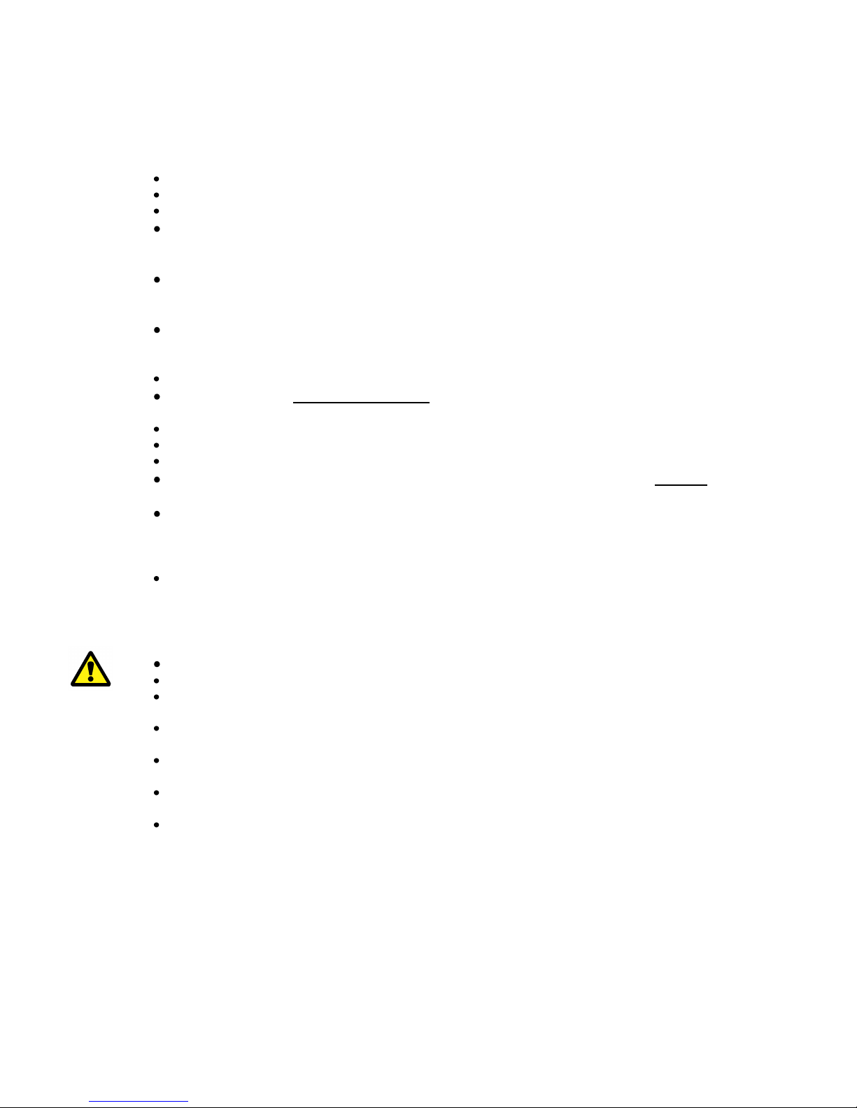
Turn on the main switch of the windlass.
When the main switch of the anchor windlass has been
switched off, you must press the down button first.
Keep this button depressed for at least 1 second to drop
the anchor.
The windlass motor will run out for 1.5 seconds to
ensure the correct release function.
Fixed switch panel
Press the down button for at least 1 sec.
The anchor will drop.
The windlass is now released and the rope will run out
in step with the progress of the boat towards land.
Tie up the boat on land.
NB If you are using a free-fall chain windlass, the high
weight of the chain may result in the full length of the chain
being pulled out. If so, make sure to take up the slack once
you have tied the boat up.
Tighten up the slack of the anchor rope (or chain) by
pressing the up button so that the anchor settles firmly
on the seabed and pulls the boat away from land.
NB The windlass will always wind in slowly for 1.5 sec
before it switches to full speed. If you release the button
within 1.5 sec and press it again and then repeat the
process, the windlass will continue to wind in at low speed.
Setting off
Start the boat engine to charge the battery.
Check that the main switch of the windlass is
turned on.
Cast off from land.
Activate the windlass.
Keep the up button depressed, and the windlass will pull
the boat away from land. The windlass will pull the anchor
up at full speed until the first auto stop is activated.
NB This ONLY applies for rope windlasses and requires the
anchor rope to be correctly fitted with brass wire markers.
NB Keep an eye on the anchor when it leaves the
water and seats in the anchor bracket. This will
allow you to stop the windlass and prevent
damage if the anchor pulls up foreign objects
from the seabed.

ENGBO AS –et selskap i Engbo-gruppen
BESØKSADRESSE: Wirgenesvei 7, 3157 Barkåker POSTADR: Postboks 2288 Postterminalen, 3103 Tønsberg
E-MAIL: suppo[email protected] WEB: www.engbo.no TLF: +47 33 00 31 50 FAKS: +47 33 00 31 60
6
NB If the windlass is straining while raising the anchor, it
would be a good idea (and save power) to run the windlass
in periods. Once the boat has begun to move backwards,
you can release the up button and then run the windlass in
periods.
Release the up button, press again and keep
depressed.
The windlass will continue to raise the anchor slowly
until the second auto stop is activated, stopping the
windlass completely.
The anchor will then be correctly seated in the anchor
bracket.
Attach the safety line to the anchor.
Turn off the main switch of the windlass.
Have pleasant sailing!
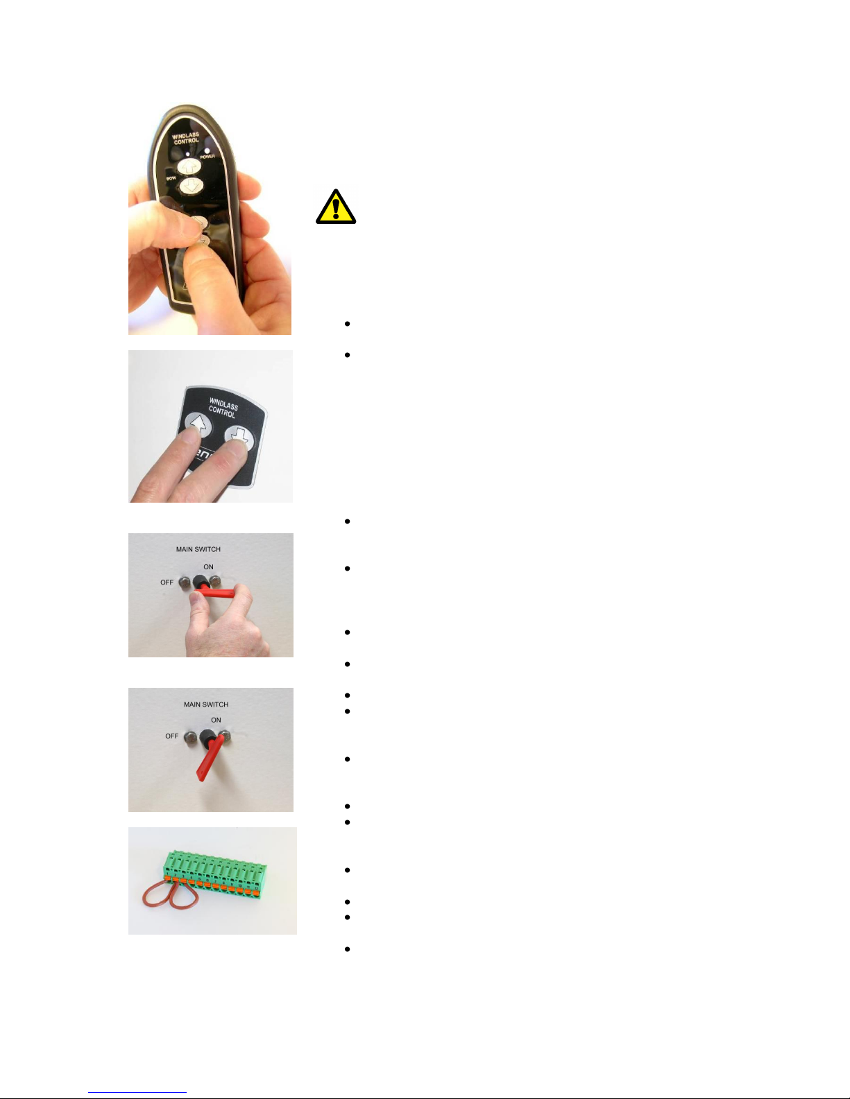
Wireless remote control
To switch on the remote control, keep one of the
buttons depressed for 1.5 sec. The green “power”
indicator will light up, and you will hear a brief audio
signal.
Every time you subsequently press a button, the
associated indicator will light up, and the remote will
emit an audio signal.
To ensure a long lifetime, the remote control switches
off automatically 5 min. after the last button was
pressed. Automatic shut-off is preceded by two short
audio signals and the “Power” indicator flashing.

ENGBO AS –et selskap i Engbo-gruppen
BESØKSADRESSE: Wirgenesvei 7, 3157 Barkåker POSTADR: Postboks 2288 Postterminalen, 3103 Tønsberg
E-MAIL: suppo[email protected] WEB: www.engbo.no TLF: +47 33 00 31 50 FAKS: +47 33 00 31 60
7
Anchor down
When the remote control is switched on, you can drop
the anchor by pressing the “down” button in. Keep this
button depressed for at least 1 second to drop the
anchor.
The windlass will then run out for 1.5 seconds to
ensure the correct release function.
Anchor up
When the anchor has dropped to the seabed, press the
“up” button to take up the slack. The windlass will
continue to winch in as long as you keep the “up”
button depressed. If the remote control has switched
off automatically (i.e. if you have not pressed a button
for more than 5 min) it will first switch on and then
immediately start to wind in the anchor rope/chain. The
windlass always starts to operate for 1.5 sec at reduced
speed before increasing to full speed.
This means that you can keep the windlass operating at
low speed by releasing and pressing the “up” button
repeatedly as required.
The “Power” indicator information:
Green light indicates that the remote control is ready
for use.
Orange light indicates that the power supply to the
windlass is not optimal, or that the windlass is
overloaded and needs time to cool down.
Red light indicates a system error or that the battery
charge is too low for the windlass to operate.
Red light flashing slowly accompanied by short
audio signals indicates that contact with the electronic
unit (receiver) cannot be established.
NB These error notifications will continue for as long as a
button is depressed.
Forced operation of the windlass
If you need to raise the anchor a little further than the
second “auto stop”mark, you can do so by keeping the
“up” button depressed for more than 10 seconds. The
windlass will then operate at low speed for as long as you
hold the button in.
NB. The use of this function must be closely
controlled to prevent damage.
ENGBO AS –et selskap i Engbo-gruppen
BESØKSADRESSE: Wirgenesvei 7, 3157 Barkåker POSTADR: Postboks 2288 Postterminalen, 3103 Tønsberg
E-MAIL: suppo[email protected] WEB: www.engbo.no TLF: +47 33 00 31 50 FAKS: +47 33 00 31 60
8
A brief description of the Engbo anchor system
Engbo MAXI windlasses is a common designation for
1000/1500 W, 12/24V Engbo windlasses. Some of the
models are most suitable for fitting aft, some fore, and
others both fore and aft. Engbo MAXI windlasses are
designed for boats larger than around 25 feet. These
windlasses –with the exception of type 33 –are
authentic free-fall windlasses, which means that a
neutral position in the windlass gears allows the anchor
to drop directly to the seabed immediately after the
“anchor down” (arrow down) button has been pressed.
The system is based on allowing the weight of the
anchor on the outside of the anchor bracket to define
how quickly the anchor drops. Therefore, it is
important to avoid unnecessary friction between rope
and hull, rollers and/or guides.
Example: If you fit the windlass with a Bruce anchor,
you will need to use the jointed anchor bracket and
ensure that the angle between horizontal and the rope
is at least 15–20º. If the angle is too narrow, the
anchor will “balance” and need “assistance” to tip out.
Electronic control unit
Engbo MAXI windlasses are fitted with modern
electronics that consist of:
Transistor-controlled power electronics that
replace the conventional cut-in relay. The new
electronic unit contains no open contacts and is very
flexible as regards voltage.
The control electronics are software-based and
feature an integrated radio receiver that
communicates with the wireless remote control, and
a built-in system to protect the windlass motor and
electronic components. Other functions controlled
electronically are two “up” speeds and two automatic
stop indicators for seating the anchor.

ENGBO AS –et selskap i Engbo-gruppen
BESØKSADRESSE: Wirgenesvei 7, 3157 Barkåker POSTADR: Postboks 2288 Postterminalen, 3103 Tønsberg
E-MAIL: suppo[email protected] WEB: www.engbo.no TLF: +47 33 00 31 50 FAKS: +47 33 00 31 60
9
Switch panels
12-79000
Standard touch panel
The windlasses are supplied as standard with 1 x
watertight (IP 68) touch panel (12-79000) for
installing in a readily accessible place in the cockpit.
If only this touch panel is to be fitted, it must, for
safety reasons, be positioned so as to allow the
operator a clear view of the anchor as it is raised and
seated in the anchor bracket.
The panel comes with a self-adhesive surface, but if
you prefer, it can be seated more firmly using the
screws supplied.
12-47020
12-47021
Wireless remote control
Three different wireless controls are available;
12-47020 designed for controlling two separate anchor
winches, 12-47021 two winches and two thrusters and
12-47022 for controlling up to six different
anchor/mooring winches.
The remote control is splash proof and features a
modern, compact design with strips of “anti-slip
material” on the rear surface. It will also float if
dropped over board.
Two-way narrow-band radio communication
guarantees the transmission of unique code to ensure
that the signal controls only your windlass.
An indicator light shows the voltage level or overload.
Range of more than 30 m in normal conditions.
The remote control uses three standard AAA (LR03)
batteries –included. For normal operation, the
batteries have a service life of more than two seasons.
A wrist/neck strap is supplied as standard.
12-47022

ENGBO AS –et selskap i Engbo-gruppen
BESØKSADRESSE: Wirgenesvei 7, 3157 Barkåker POSTADR: Postboks 2288 Postterminalen, 3103 Tønsberg
E-MAIL: suppo[email protected] WEB: www.engbo.no TLF: +47 33 00 31 50 FAKS: +47 33 00 31 60
10
Holder for wireless remote control
The enclosed, handy holder (12-47030), keeps the
wireless remote located in the right place when not in
use.
The holder kit consists of two single parts, and the holder
to and the bracket.
Slide the holder into the bracket by the slots.
Fix the bracket to the base with the adhesive tape.
By turning the backside of the remote forward and
fit it in the holder, the buttons will be protected
from unwanted activating of the winch or thruster
when kept in the pocket.
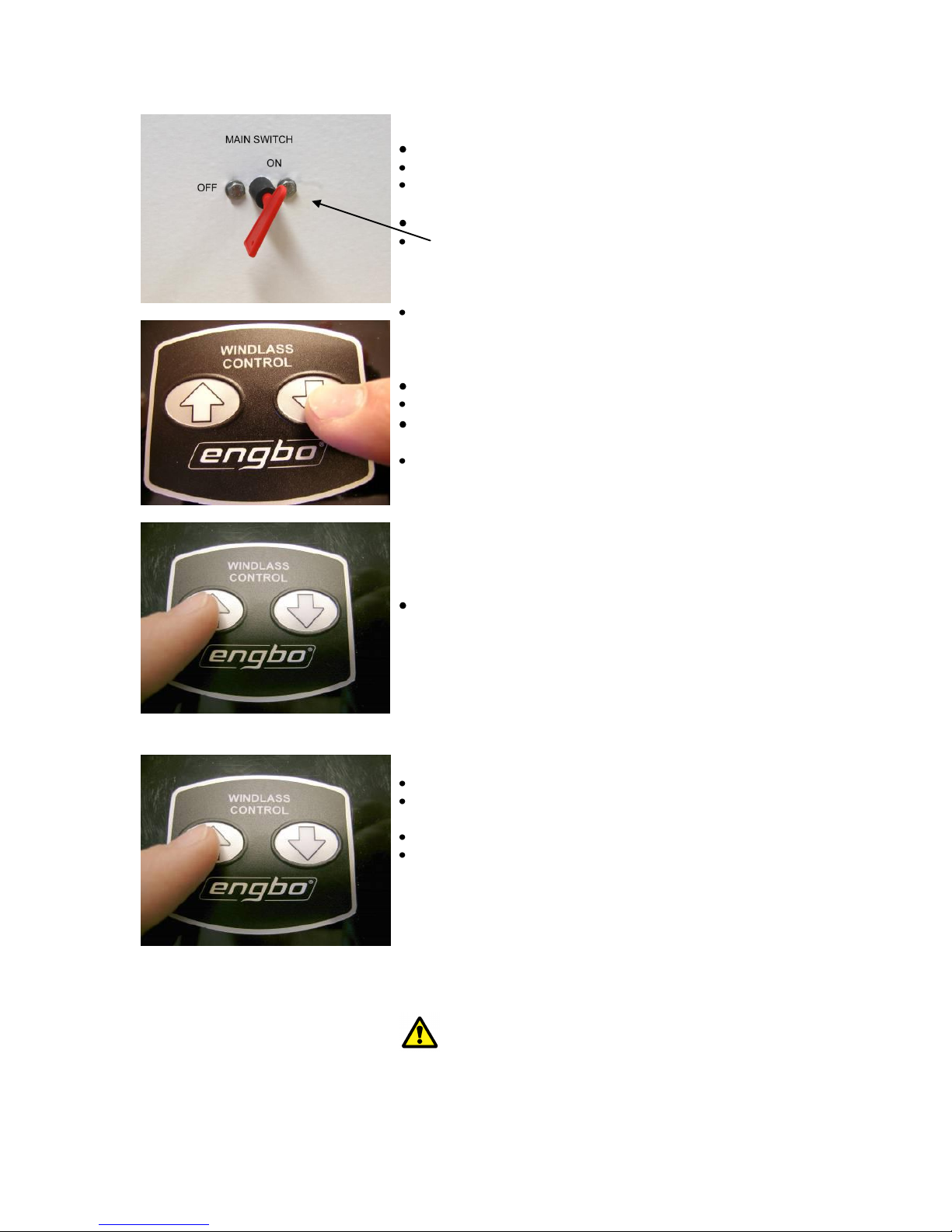
Installation –general
The windlass should be positioned as high as possible to allow maximum space for the rope
that will be stored below the windlass. The height from the bottom of the well where the rope
is stored to the bottom edge of the line wheel should be at least 50 cm, and the area
should be at least 40 x 40 cm to allow room for 50 m x 15 mm anchor rope. This will
prevent the rope from bunching under the windlass, and assure sufficient friction between the
line wheel and the rope.
See the specific descriptions for the separate windlass models.
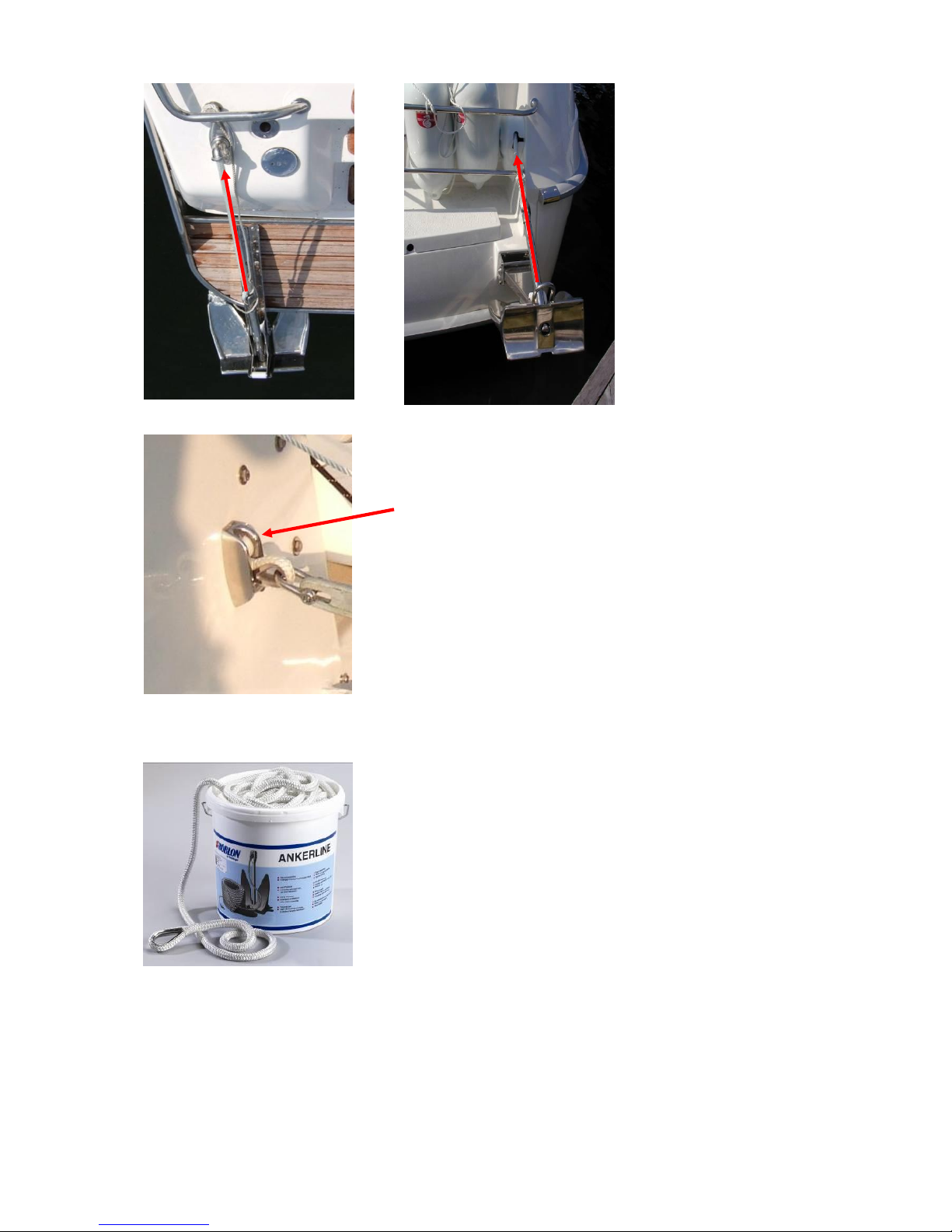
The anchor bracket
Fit the windlass so that the rope is wound up in line with the anchor bracket (see pictures 1
and 2) –numerous different models are available –positioned on the exterior of the boat. The
anchor bracket functions as a guide for the rope when the anchor is on the seabed and as a
“seating point” for the anchor once it has been raised.
ENGBO AS –et selskap i Engbo-gruppen
BESØKSADRESSE: Wirgenesvei 7, 3157 Barkåker POSTADR: Postboks 2288 Postterminalen, 3103 Tønsberg
E-MAIL: suppo[email protected] WEB: www.engbo.no TLF: +47 33 00 31 50 FAKS: +47 33 00 31 60
11
Picture 1
.
Picture 2
Hull conduit / Line guide
It will often be necessary to install a hull conduit with a
pulley that guides the rope with low friction through the
hull.
The hull conduit will also prevent large volumes of water
from leaking in. (When fitting the MAXI 34V or MAXI 40 on
the inside of the stern, it will often be possible to adjust
the hull conduit so as to prevent friction between the hull
and the rope.)
Anchor rope
Engbo supplies original woven anchor rope with a lead
core in the whole length of the rope along with a fine
special thimble that will not snag on the pulley or bracket
when the anchor is dropped. This rope has been specially
designed for Engbo anchor windlasses and is a
precondition for problem-free operation of the system.
Supplied in various lengths and dimensions. The Engbo
Maxi range generally uses 16 mm line. If the available
space for storing the line is limited, 14mm line could be an
alternative.

ENGBO AS –et selskap i Engbo-gruppen
BESØKSADRESSE: Wirgenesvei 7, 3157 Barkåker POSTADR: Postboks 2288 Postterminalen, 3103 Tønsberg
E-MAIL: suppo[email protected] WEB: www.engbo.no TLF: +47 33 00 31 50 FAKS: +47 33 00 31 60
12
Safety line
Once the anchor is seated in the anchor bracket, it must
be secured with the safety line supplied. This prevents the
anchor from dropping unintentionally.
Auto stop
Engbo MAXI winches for anchor lines feature an advanced
electronic auto stop switch that stops the windlass
automatically, twice. The first stop comes just before the
anchor reaches the anchor bracket. The windlass can then
only be operated at low speed until it stops for the second
time once the anchor is seated correctly in its bracket –
ready to be dropped next time.
NB The fitting procedures for the different models are described in separate
chapters.
Wireless remote
Fitting antenna
Before starting to operate the wireless remote, the
electronic unit must be fitted with an aerial. In addition, the
remote control and electronic unit must be coded/
electronically instructed to communicate with one another.
Remove the left-hand rubber plug on the electronic unit
(the one closest to the Engbo logo).
Pierce the plug (to one side) with the aerial.
Depress the female socket of the aerial holder and press
the aerial fully into the clip.
Release the female socket and the aerial will be secured in
position.
Replace the rubber plug. Start by pressing the part of the
rubber plug through which the aerial has been inserted,
and continue around the edge until the plug is firmly
seated.
Make sure not to twist the plug and deform the aerial.
NB The remote control will function at short distances even if the
aerial is not fitted.
ENGBO AS –et selskap i Engbo-gruppen
BESØKSADRESSE: Wirgenesvei 7, 3157 Barkåker POSTADR: Postboks 2288 Postterminalen, 3103 Tønsberg
E-MAIL: suppo[email protected] WEB: www.engbo.no TLF: +47 33 00 31 50 FAKS: +47 33 00 31 60
13
Coding of the wireless remote control
Image A
Image B
Image C
Image D
Image E
Procedure for wireless remote controls with serial
no. above 8600
Important!
If your wireless control has serial no. lower than 8600,
use the procedure enclosed your remote.
If coding a wireless control with serial no. above 8600 is
to be coded to a receiver with Soft Ware of previous version be
aware that the remote will be ready for operation after 10 sec.
How to put the wireless control unit in code mode:
Select the pair of switches on the remote control to be
coded.
Press down both switches simultaneously for
approximately 12 seconds. When you hear a short
sound signal and the green power light starts to flash,
the remote control is prepared for coding and will stay
in coding mode for 5 minutes or until the coding has
been finished.
(Image A)
How to put the receiver unit in code mode:
Alt. 1. Touch panel installed.
Press and keep both switches on the touch panel down
while simultaneously switching on the power to the
receiver unit.(Image B and C)
The receiver will now understand that coding is
requested and automatically connect to your wireless
control and the wireless remote control will immediately
be ready for use.
This will be confirmed by a short sound signal and the
green power light will turn from flashing to permanent.
Check that the wireless control is functioning.
Alt. 2. Joystick installed.
Turn the thruster main switch off.
Disconnect the cables to the joystick connected to 1, 2
and 3 on the green plug on the remote control unit
(RCU).
Prepare two short wires (5 cm). Remove the insulation
in both ends and connect these between 1 and 2 as well
as between 2 and 3 on the green plug. (Image D).
Turn the power on.
The receiver will now understand that coding is
requested and automatically connect to your wireless
control and will immediately be ready for use.
This will be confirmed by a short sound signal and the
green power light will turn from flashing to permanent.
Turn the thruster main switch off.
Disconnect the short wires and connect the joystick
cables.
Turn the power on and check that the wireless control is
functioning.

ENGBO AS –et selskap i Engbo-gruppen
BESØKSADRESSE: Wirgenesvei 7, 3157 Barkåker POSTADR: Postboks 2288 Postterminalen, 3103 Tønsberg
E-MAIL: suppo[email protected] WEB: www.engbo.no TLF: +47 33 00 31 50 FAKS: +47 33 00 31 60
14
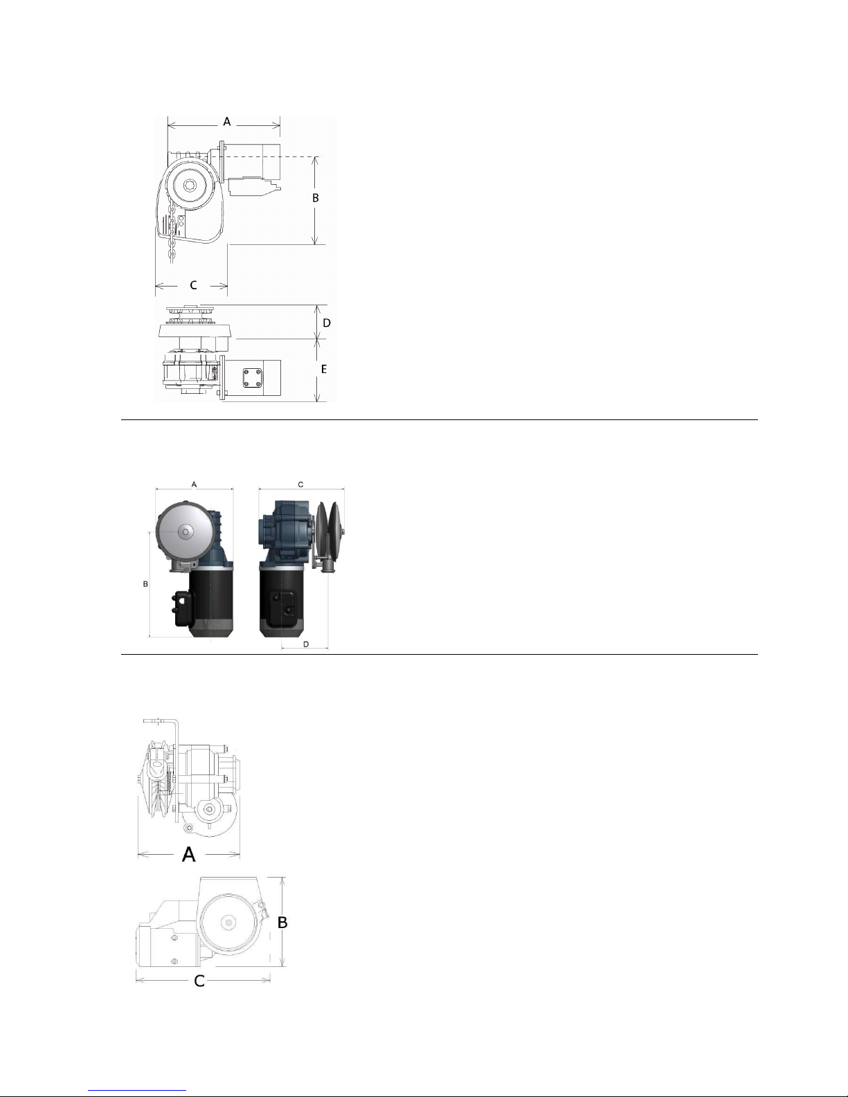
Dimensional sketches
Maxi 31/40 –series
A: Height
B: Length
C: Width incl. line wheel
D: Width excl. line wheel
200 mm
370 mm
230 mm
160 mm
Maxi 32 –series
A: Height above deck
B: Length above deck
C: Width above deck, incl. line wheel
D: Width excl. line wheel
E: Height below deck
200 mm
255 mm
230 mm
160 mm
150 mm
ENGBO AS –et selskap i Engbo-gruppen
BESØKSADRESSE: Wirgenesvei 7, 3157 Barkåker POSTADR: Postboks 2288 Postterminalen, 3103 Tønsberg
E-MAIL: suppo[email protected] WEB: www.engbo.no TLF: +47 33 00 31 50 FAKS: +47 33 00 31 60
15
Maxi 33 –series
A: Total width below deck
B: Total length above deck (cover)
C: Total width above deck (cover)
D: Height above deck
E: Height below deck
350 mm
220 mm
160 mm
90 mm
160 mm
Maxi 34-series
A:
B:
C:
D:
200 mm
271 mm
220 mm
120 mm
Maxi 38-series
A: Total width
B: Total height
D: Total length
220 mm
230 mm
370 mm

ENGBO AS –et selskap i Engbo-gruppen
BESØKSADRESSE: Wirgenesvei 7, 3157 Barkåker POSTADR: Postboks 2288 Postterminalen, 3103 Tønsberg
E-MAIL: suppo[email protected] WEB: www.engbo.no TLF: +47 33 00 31 50 FAKS: +47 33 00 31 60
16
Technical
specifications
ENGBO MAXI 31, 32, 33, 34, 38 and 40
Motor output, nom.
-12V DC / 1000 W
-24V DC / 1500 W
Rope
(for rope windlasses)
Woven lead rope: dia. 16 mm. Breaking strain: 4000 kg
Woven lead rope: dia. 14 mm. Breaking strain: 3300 kg
Length:
50 m, weight, 21.7 kg
75 m, weight, 32.0 kg
100 m, weight, 43.0 kg
Chain (for chain
windlasses)
6.5 mm, short link Norwegian std. Breaking strain: 2300 kg
8 mm DIN 766 std. Breaking strain: 4000 kg
Pulling power
(Electronically governed)
Rope windlasses:
1000 W, up to approx. 500 kg
1500 W, up to approx. 650 kg
Chain windlasses: up to approx. 850 kg
Pulling speed
20–25 m/min with a load of approx. 40 kg
Power consumption
80–200 A during normal operation
Recommended fuses
1000 W/12V and 1500 W/24V, 250 A
Recommended min.
battery capacity
12V/100Ah
24V/75 Ah
Weight: windlass with
motor and cables
Approx. 20 kg
Weight: electronic unit
2.3 kg
Auto stop function
Yes (NB Only for rope windlasses)
Recommended anchor/
weight
Engbo / Bruce / Spade /10–30 kg
Recommended boat size
Over 25-foot
Fitting
See the separate descriptions for the individual models
Standard equipment
Windlass incl. cables for electronic module, electronic
module, switch panel and main power switch
Supplementary
equipment
Anchor (Multiple types)
Anchor bracket (Multiple types)
Battery cable
Lead rope or chain
Fuse w/holder
Hull conduit for rope or chain
Wireless remote control

ENGBO AS –et selskap i Engbo-gruppen
BESØKSADRESSE: Wirgenesvei 7, 3157 Barkåker POSTADR: Postboks 2288 Postterminalen, 3103 Tønsberg
E-MAIL: suppo[email protected] WEB: www.engbo.no TLF: +47 33 00 31 50 FAKS: +47 33 00 31 60
17
Electrical wiring
The label on the cover of the electronic unit also shows a diagram for connecting the electrical
cables, - but always verify correct connections with wiring diagram.
IMPORTANT
Always switch off the power at the main switch and/or disconnect the battery
before working on the wiring connections.
Switch panel
Standard touch panel (Item no. 12-79000)
The windlasses are supplied as standard with 1 x
watertight touch panel for installing in a readily accessible
place in the cockpit.
If only this touch panel is to be fitted, it must, for safety
reasons, be positioned so as to allow the operator a clear
view of the anchor as it is raised and seated in the anchor
bracket.
The panel comes with a self-adhesive surface, but if you
prefer, you can use the corner holes to screw it firmly in
position.
Drill an hole (dia. 18 mm) in the place where the panel
is to be fitted.
Run the panel cable through the hole.
Remove the protection tape from the rear surface of
the panel and affix the panel firmly to the surface.
Run the cable to the electronic control box.
Cut off any surplus cable and strip the ends of the
three wires that are to be connected to the terminal
clips as described in the connection diagram. (Picture
of control box).
Connecting the switch panel
The windlasses are supplied as standard with one switch
panel and 10 m of cable. Cut the wires to the required
length and strip approx. 10 mm from their ends. Twist
the wires in the separate cables and attach the cables to
the green terminal box by pressing in the orange button
above the appropriate hole and keeping it depressed
while you insert the cable. Release the button once the
cable is in place. Check that the cable is seated firmly
and that the insulation is inside the terminal clip so that
no loose wires are sticking out.
Connect the cables as follows:
1: White
2: Brown
3: Green
If you wish to connect additional panels, connect the
cables in parallel to 1, 2 and 3. (2 is the common 0 V).
(Spring-lock terminal clips have been chosen rather than
screw clips to prevent problems linked to vibrations
and/or changes in temperature causing the clips to
loosen).

ENGBO AS –et selskap i Engbo-gruppen
BESØKSADRESSE: Wirgenesvei 7, 3157 Barkåker POSTADR: Postboks 2288 Postterminalen, 3103 Tønsberg
E-MAIL: suppo[email protected] WEB: www.engbo.no TLF: +47 33 00 31 50 FAKS: +47 33 00 31 60
18
Connecting the auto stop switch
NB Only applies to rope windlasses.
Auto stop switch
Connect the cables from the auto stop switch in the same
way as described above.
Connect the cables as follows:
4: Brown (BN) = +V
5: Black (BK) = Signal
6: Blue (BU) = Gnd
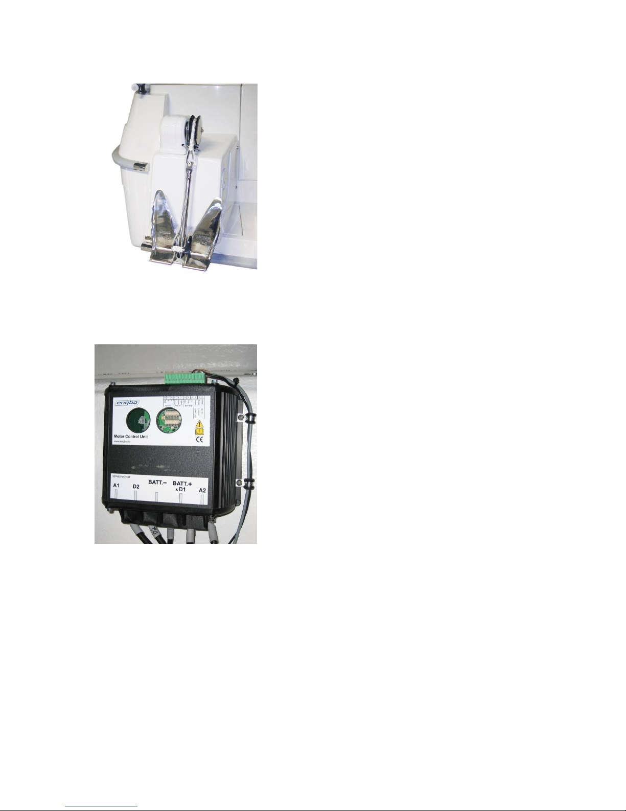
Connecting the motor and battery cables
It is best to connect the cables from the battery and
motor to the electronic unit first, before fastening the
unit upright against the bulkhead with the cables bent
down over it.
Start by connecting the motor cable marked (A1) to the
left. NB The lock nuts are on the left-hand side.
Then connect motor cable (D2) and then the black (-)
battery cable. Then connect the red (+) battery cable to
(D1) from the motor. Finally, connect (A2) from the
motor. (If necessary, remove in the reverse order). It is
best to use a pair of pliers, as shown in the picture.
The picture shows the correct connection and the
direction of the bolts and cables.
NB The cable shoes must be connected directly to the
copper bars without washers or anything else between.
Use flat washers between the bolt heads and the top
sides of the cable shoes, and between the plastic side of
the end panel and the locking nuts.
The M8 x 25 mm bolt is for the positive battery cable.
Please note that on this terminal, there are two cable
shoes that have to be connected.
NB Connect the cable shoes as shown in the picture to
ensure best possible contact.
NB When the cable length (one way) between the battery
and electronic unit is up to 5 m, use 35 mm2cable. For
longer distances, use 50 mm2cable.

ENGBO AS –et selskap i Engbo-gruppen
BESØKSADRESSE: Wirgenesvei 7, 3157 Barkåker POSTADR: Postboks 2288 Postterminalen, 3103 Tønsberg
E-MAIL: suppo[email protected] WEB: www.engbo.no TLF: +47 33 00 31 50 FAKS: +47 33 00 31 60
19
IMPORTANT
The anchor winch shall not be installed in areas which may contain
flammable or explosive gasses.
In cases where this is not possible, the winch can be built into closed
space, but with ventilation to open air.
The MCU must be installed in dry place in such in a way that no cables
with current may be short circuited.
Battery connection
WARNING!
Check that none of the cables is short-circuited or damaged before
connecting the battery.
Check that all power cables and connection points are tightly secured –
post-tighten if necessary.
NEVER use washers between cable shoes and connection points in places
where high voltage currents pass.
A fuse and main power switch must be fitted to the positive battery cable, as close to
the battery as possible. (See the connection diagram).
The windlass must always be connected to the start battery.
Remember to turn off the main power switch when the windlass is not in use.
Main power switch
The picture shows the battery cable correctly
connected to the main power switch, with
rubber caps insulating the connection points.
Fuse and fuse holder
The fuse holder and fuse are to be fitted to the
(+) cable between the battery and the
electronic control unit of the windlass. See the
electrical connection diagram.
This picture shows correct connection of the
battery cable to the fuse-holder terminal.
NB The fuse must be fitted directly above the
cable shoe. There must NOT be any washers or
nuts between them.
Fit washers on both sides. Recommended
torque: 13–15 NM. Fit plastic caps on the top of
the cover.
Washer
Fuse
Cable shoe
Washer

ENGBO AS –et selskap i Engbo-gruppen
BESØKSADRESSE: Wirgenesvei 7, 3157 Barkåker POSTADR: Postboks 2288 Postterminalen, 3103 Tønsberg
E-MAIL: suppo[email protected] WEB: www.engbo.no TLF: +47 33 00 31 50 FAKS: +47 33 00 31 60
20
Electrical wiring diagram
This manual suits for next models
4
Table of contents
Other Engbo Boating Equipment manuals


