Marpac 7-1545 Quick start guide

For Windlass Models
7-1550 & 7-1546
Boats to 20 Feet
Owner’s Installation &
Operation Manual
If unfamiliar with this product and
installation seek a professional installer.
Please read this user manual carefully before using the product

1
Page
Table of Contents
Section Description Page
I Features 2
II Package Contents 2
III Specifications 3
IV Installation 4
V Operation 9
VI Maintenance 12
VII Warranty 12
VIII Accessories 13
IX Spare Parts 14
For Anchor Windlasses 7-1545 & 7-1546
Version 013010
™

2
Page
Section I
Section II
Package Contents:
Part Description Qty
Windlass 1
Control Device 1
User Manual 1
Installation Video CD 1
Mounting Template 1
Part Description Qty
Threaded Rod
M8 x 100 mm
4
Nut M8 4
Washer M8 4
Spring Washer M8 4
Accessories
Features:
Gypsy can take both chain and rope.
Heavy duty DC motor with long life and high output torque
Selectable free fall or power out mode (for free fall model)
Aluminum alloy housing with powder coated finish
Compact one-piece housing to ensure water resistance
Simple deck mounting with no parts under deck
Strong structure ensures long performance life
Step by step installation video CD included

3
Page
7-1545 7-1546
Fits Boats Up to 20 ft Up to 20 ft
Input Voltage DC 12V DC 12V
Max Working Load 265lb (120kg) 265lb (120kg)
Typical Working Load 45lb (20kg) 45lb (20kg)
Retrieval Speed 57ft(17m)/min 57ft(17m)/min
Pay-Out Speed 73ft (22m)/min Free Fall or
57ft(17m)/min
Continuous Working Time 15 min. 15 min.
Current Draw (Typical) 12 amp 12 amp
Motor Type Permanent Magnet Permanent Magnet
Motor Wattage I/O 600W / 250W 600W / 250W
Motor Efficiency 74% 74%
Gear Type/Efficiency Worm / 50%~88% Worm / 50%~88%
Chain Size 1/4” (7mm) G4 HT 1/4” (7mm) G4
HT
Rope Size 1/2” (12mm)
3 Strand
Medium Lay
1/2” (12mm)
3 Strand
Medium Lay
Dimensions
(L x W x H)
9” x 4.75” x 5.3”
(230x120x135mm)
9” x 4.75” x 5.3”
(230x120x135mm
)
Weight 8.8lb (4.0kg) 10.6lb (4.8kg)
Section III
Specifications:

4
Page
It is very important to choose the correct type of rope and chain,
to ensure proper running of the windlass.
Rope- Must use three strand, medium-lay. We recommend Filament
Polyester, Premium Nylon Do not use soft rope. Soft rope (either
polyester or nylon ) will slip and cause a rope jam in the gypsy. It will
also lock the gypsy and cause circuit breaker to pop-up often.
Chain- Must ensure that the distance between every other link “d” is
suitable for the gypsy. Please refer to the chart below.
Section IV
Installation: (Reference to Video CD)
1. Required Tools:
Electric Drill
with 3/8” Bit
Jigsaw Phillips Head
Screwdriver
Adjust-
able
Wrench
Fil
e
Calking Gun
and Silicone

5
Page
2. Inspect the Bow:
a. First of all, a suitable Bow
Roller must be installed to sup-
port the anchor, chain and rope.
b. A cleat, bollard or snubbing
device should be installed
between the bow roller and the
windlass to tie the rope on while
laying anchor or securing the
anchor in the fully raised
position.
c. If you are using only chain, a
chain stopper should be installed
between the bow roller and the
windlass to take the drag force
away from the windlass while
being anchored.
d. Make sure the anchor well or
the chain locker is deep enough
to store chain and rope. The
minimum depth is 1 1/3 ft
(40cm) to store about 100ft (30
meter) of rope. If the anchor
well is not deep enough the rope
will build up very quickly and
block the entry.
gypsy
bollard
bow roller windlass
bow roller windlasschain stopper

6
Page
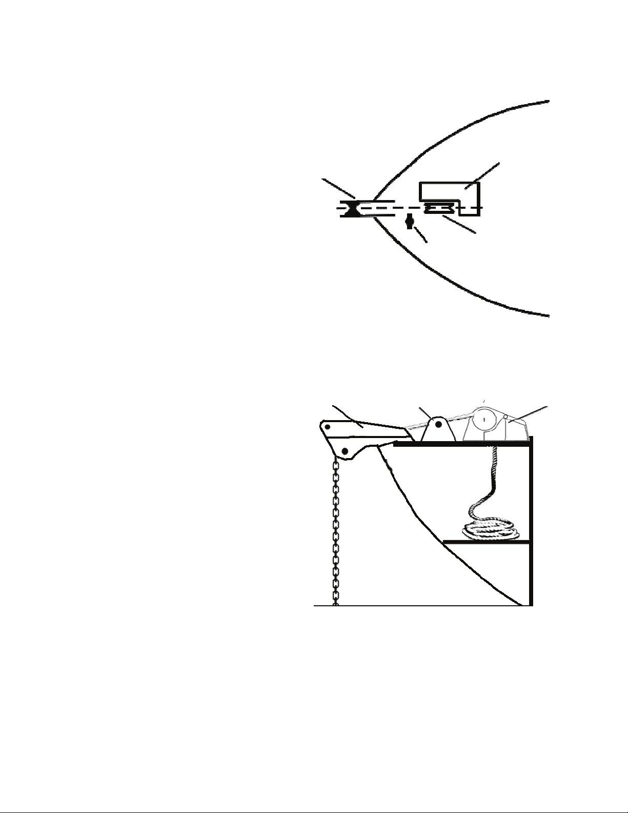
3. Placement of the Windlass:
a. Place the windlass on the deck and find a suitable position for it,
with reference to the vessel’s bow roller, rope and chain locker be-
low.
b. Place the mounting template on the deck in the desired position for
the windlass and hold it in place using adhesive tape.
c. Use a 3/8” (10mm) diameter drill to make four holes for the mount-
ing thread rods and make a fifth hole to pass power supply cables
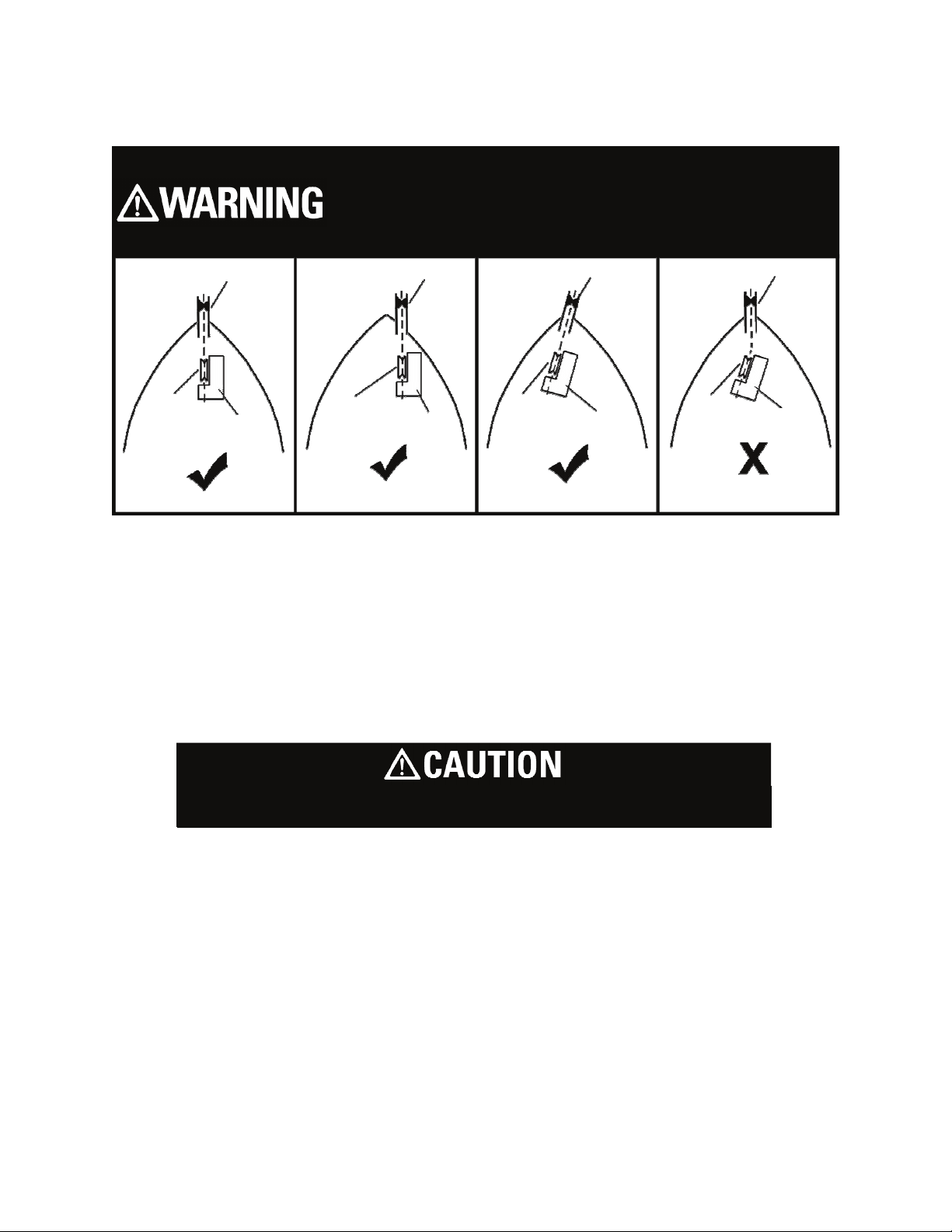
bow roller bow roller bow roller
bow roller
gypsy gypsy gypsy gypsy
windlass windlass windlass windlass
CORRECT CORRECT CORRECT INCOR-
Note: Placement of the windlass is important
to correct operation. If unfamiliar with this
product and installation, seek a professional
d. With a jigsaw, cut the hole for the rope and chain to pass through.
Use a file to smooth any rough edges. To avoid water absorption by
the deck, apply paint to the cut hole edges.
e. Secure thread rod to the base of the windlass, then apply a silicone
sealant around thread rod. Secure the windlass firmly to the deck
from below using the nuts and washers supplied.
f. Apply silicone sealant (Marpac 7-2505 or 7-2507 is recommended)
around the outside of the base.
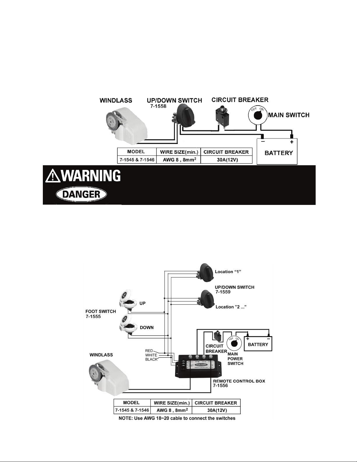
g. Mount control device at a suitable position either in the cabin or
close to the operating area.
Verify all markings for mounting location prior to

7
Page
h. Connect the windlass, control unit and power source using electric
cable indicated below. Keep the power supply cable as short as
possible. Too thin and/or too much length of electric cable will
reduce the performance of the windlass or cause the circuit breaker
to work incorrectly.
i. Using foot switches or multiple control switches, a “Remote Control
Box (reversing solenoid) 7-1556” is necessary.
For better performance, we recommend to use “Remote Control Box”
instead of “7-1558” for the 7-1553 & 7-1554 windlasses.
For safety reasons, DO NOT connect the power
source direct to the battery. Please connect the
power cable to the main power switch on your

8
Page
4. Install Anchor Rope and Chain:
It is highly recommend you use a factory-spliced
Anchor Rope and Chain. Do not use a hook or
Recommended Marpac™ Anchor Rodes are:
Specially treated 3-strand windlass grade nylon rope
that remains flexible even with constant exposure to sun
and salt water
High test, hot-dipped galvanized chain
Tapered back splice for a smooth transition from rope to
chain
Marpac
No.
G4 Chain Rope Total
Length
7-6455 10’ x 1/4” 150’ x 1/2” 160’
7-6456 15’ x 1/4” 200’ x 1/2” 215’
7-6457 15’ x 1/4” 300’ x 1/2” 315’
The Best Marpac™ Anchor Rodes are:
Special 8 plait rope that eliminates all hockling and kink-
ing, and reduces the risk of jamming the windlass gypsy
8 plait rope resists stiffening with age and enables 50%
more line in the anchor locker
High test, galvanized chain
Include a stainless steel swivel to make it difficult for the
chain to get twisted
Marpac
No.
G4 Chain Rope Total
Length
7-6450 10’ x 1/4” 125’ x 1/2” 135’
7-6451 10’ x 1/4” 200’ x 1/2” 210’
7-6453 15’ x 1/4” 300’ x 1/2” 315’

9
Page
Section V
Operating:
1. Rotate the 7-1558 to the “DOWN” position to pay out or free fall the
anchor. Rotate to the “UP” position to retrieve the anchor. Make
sure the switch is rotated to “OFF” when not in use.
Note:
You can set the rotating “Free Fall” switch (in the right hand side of
windlass) by a flat screw driver to be a “on” (free fall) mode or
“off” (Power Out) mode.
Note:
Please free fall the anchor to the bottom in one fall.
(Do not release the control switch during the anchor’s fall.)
Note: Running-In Gears:
It is normal in the initial period (under load) to observe a noise, a lack
of power or circuit breaker to pop often. This is caused due to the
worm gears Running-In. After about 10 uses, the gears will become
smooth, resulting in a regain in power and a reduction of noise.
2. For free fall model only: when releasing the anchor, rotate the
switch “DOWN” once to free fall the anchor to the sea bed (clutch
will stay at open), until the current has drifted the boat to a desired
location and the anchor has cast firmly in the sea bed, rotate the
switch “UP” once to engage the clutch.
The included circuit breaker is a push button
style. If the button bounces, it means the motor
is overloaded. Press the button once to reset.

10
Page
3. Pay out the rope and chain approximate 2~3 times the water’s depth
for a firm casting while being anchored.
2~3 times the water’s depth
water’s
Keep limbs, fingers clothing and hair
clear of the windlass and anchor to avoid
possible personal injury during opera-
4. Tie the anchor rope firmly to the bollard when the anchor is cast
and the boat is moored. Do not allow the windlass to take the force
of a boat’s drag. If using all chain, a chain stopper is necessary to be
installed between bow roller and windlass to take the force of boat’s
drag.
To prevent damage to the windlass
always pay out the line until the rope
(NOT the chain) is on the gypsy. This is
especially important for mooring in
shallow waters. The tension in the rope
will reduce the impact of the boat’s drag
when moored.
Do not use
free fall function
when using all chain

11
Page
Move the boat to just above the anchor by the boat’s engine power (not wind-
lass) and switch on the windlass to lift it back
Note: The windlass is designed to lift the anchor rather than to
drag the boat or for mooring.
6. If the anchor is stuck on the seabed or reef, detach it by the boat’s
engine power before operating the windlass or else it may cause
damage or the load may overstrain the windlass.
7. After use, secure the anchor firmly in place in the boat to avoid
damage causing by anchor falling during transport.
8. The anchor windlass is not designed for continuous operation for
long periods. Do not use for more than 20 minutes at a time under
loading. Allow an interval of 20 – 30 minutes after each operation.
OPERATING SAFETY IS THE FIRST
5. When retracting the anchor, untie the rope from bollard. Then move
the boat to the position just above the anchor by boat’s engine power
(not the windlass power) and switch on the windlass to drag it back.
When the anchor is close to the bow roller, slow down the roll in by
pausing the switch.

12
Page
Section VI
Maintenance:
1. The windlasses come with a grease lubricated gear box. There is no
need for extra lubrication.
2. In order to make the windlass perform at optimize capacity and ex-
tend its life, use fresh water to wash off salt water after each use.
3. Periodically check the electric joiner and the silicon sealant.
Section VII
Warranty:
1. The warranty is deemed as effective only under conditions of normal
operation, maintenance and without modification of the product.
2. CLAIMS
If the product needs servicing, please send it back (or bring it to us)
with the proof of purchase and we will investigate the product free of
charge before repairing. However, the cost of postage or removal
from the boat will be borne by the owner.
3. LIMITATIONS AND EXCLUSIONS
The warranty will be deemed effective only if the windlass is used
on a non-commercial basis and will be invalid and excludes the fol-
lowing conditions.
a. Operation exceeds the stated specifications
b. Use for purposes other than indicated
c. Disassembly or modification of the product
d. Installation of other parts on the product.
e. Third party products even if associated or used together with
this product.

13
Page
Section VIII
Accessories:
7-1485 Foot Controls Kit
Kit Includes:
(2) 7-1555Foot Switches
(1) 7-1556 Remote Control
Box
7-1486 Add-a-Station Kit
Kit Includes:
(2) 7-1559 Up/Down Switches*
(1) 7-1556 Remote Control Box
7-1487 Combination Kit
Kit Includes:
(2) 7-1555 Foot Switches
(2) 7-1559 Up/Down
Switches*
(1) 7-1556 Remote Control
Spare parts for kits are available separately.
*7-1559 Replacement for kit switches only

14
Page
Spare parts for Windlasses only:
7-1558 Up/Down Switch (Replacement for Windlass Switches Only)
7-9086 Release Arm for 7-1550, 7-1553, 7-1554 models only
7-9088 Tension Arm fits all Marpac™ horizontal windlasses
7-9091 Tension Spring fits all Marpac™ horizontal windlasses
™
Section IX
Spare Parts:

Made and Printed in Taiwan for
Marpac™, New Orleans, LA
©2007 Marpac™
This manual suits for next models
1
Table of contents