Watt & Sea PK-610-600-PV Quick guide

RACING HYDROGENERATOR
Installation and instruction manual
HYDROGENERATOR SERIAL NUMBER
CONVERTER SERIAL NUMBER
HYDRAULIC PUMP SERIAL NUMBER
Designed and manufactured in France by :
WATT&SEA SARL
40 R Chef de Baie
17000 La Rochelle
FRANCE
www.wattandsea.com
Version
V4.1
Date
May 2019
Contact
contact@wattandsea.com

!
2
TABLE OF CONTENTS
1.!SAFETY NOTICE 4
1.1.!Mechanical hazard 4!
1.2.!Electrical hazard 4!
1.3.!Installation 4!
1.4.!Operation 4!
2.!HYDROGENERATOR pack content 5!
3.!ADDITIONAL EQUIPMENT REQUIRED 6!
4.!MECHANICAL INSTALLATION 7!
4.1.!Installing the propeller blades 7!
4.2.!Placing the device on the transom 8!
4.3.!Installing the bracket on the transom 9!
4.4.!Rigging the immersion/lifting system 10!
4.5.!Mounting the electronic converter 12!
4.6.!Mounting the hydraulic pump 13!
5.!ELECTRICAL INSTALLATION. 14!
5.1.!Three-phases wiring of the hydrogenerator 15!
5.2.!Using a solar panel 15!
5.3.!Connecting the converter to the batteries 15!
5.4.!Connecting the hydraulic pump to the batteries 17!
5.5.!Interpretation of the converter’s Leds 17!
5.6.!Interpretation of the hydraulic pump Leds 18!
6.!HYDRAULIC INSTALLATION 19!
6.1.!Connecting the hydraulic circuit 20!
6.2.!Filling the oil tank and bleeding the circuit 20!
6.3.!Pump operation 21!
7.!CHARACTERISTICS 22!
7.1.!Technical characteristics 22!
7.2.!How it works 23!
8.!MAINTENANCE 24!
9.!SPARE PARTS 24!
10.!Frequently asked questions 25!
10.1.!Operation 25!
10.2.!Maintenance and repairs 26!
11.!WARRANTY 27!
12.!REGISTER YOUR PRODUCT ONLINE 28!
13.!FORM REQUESTING AN AFTER-SALES SERVICE RETURN 29!

!
3
TABLE OF FIGURES
Figure 1 : components contents................................................................................................................. 5
Figure 2: Exploded view of the prop shaft .................................................................................................. 7
Figure 3 : Cradle dimensions.................................................................................................................... 9
Figure 4 : View of the lowering and lifting line ......................................................................................... 10
Figure 5 : Assembly of the lowering line using a low friction ring ................................................................ 11
Figure 6: Dimensions of hydraulic pump .................................................................................................. 13
Figure 7: Wiring schematic .................................................................................................................... 14
Figure 8: Phase converter wiring plan...................................................................................................... 14
Figure 9: battery connectors manual........................................................................................................ 17
Figure 10: Pump running ....................................................................................................................... 18
Figure 11: Disconnecting the quick-release couplings (© LEGRIS) ................................................................ 19
Figure 12: Hydraulic circuit blueprint....................................................................................................... 19
Figure 13: Oil filler cap ......................................................................................................................... 20
Figure 14: Racing hydrogenerator dimensions.......................................................................................... 22

!
4
1. SAFETY NOTICE
While our primary concern in designing the hydrogenerator was your safety, certain precautions must
nevertheless be taken when operating any mechanical or electrical equipment.
Please keep the following safety factors in mind when installing and operating the hydrogenerator, and be
aware at all times of the electrical and mechanical hazards inherent in operating the propeller.
1.1. Mechanical hazard
The hydrogenerator’s blades are made of a composite material and can rotate at a speed of over 100 kph
(62mph). At this speed, the blades are practically invisible and can cause serious injuries.
WARNING :
-WHEN INSTALLING THE HYDROGENERATOR, MAKE SURE THAT THE PROPELLER IS SAFELY
POSITIONED OUT OF REACH.
-DO NOT ATTEMPT TO STOP THE PROPELLER WITH YOUR HAND WHILE THE GENERATOR IS
RUNNING.
1.2. Electrical hazard
Heat in wiring systems often results from undersized cables or faulty connections.
Batteries have a very high current carrying capacity. A short-circuit in their cables may result in an outbreak of
fire. To prevent this hazard, you must install a 50 amp fuse between the converter and each battery.
If the fuse is defective, you must determine the reason before resetting or replacing it.
WARNING :
-YOU MUST INSTALL AN EXTERNAL 50 AMP FUSE.
-ALWAYS PLACE THE HYDROGENERATOR IN THE LIFTED POSITION BEFORE STARTING WORK
ON IT.
1.3. Installation
Please observe the following precautions during installation :
• Remove the hydrogenerator from the water.
• Keep safety in mind at all times ! Have someone help you throughout the duration of the installation.
• Remember : the batteries should be connected last.
1.4. Operation
• Check the support structure, blades and electric circuits on a regular basis.
• Although the propeller blades are made of very strong materials, they may warp or break if they come into contact
with a submerged object.
WARNING :
-NEVER TOUCH THE PROPELLER WHEN IT IS SPINNING.
-NEVER USE THE HYDROGENERATOR TO STEP ONTO OR OFF THE BOAT AS THIS MAY WARP
THE DRIVE SHAFT.
-WHEN RUNNING, THE CONVERTER CAN REACH VERY HIGH TEMPERATURES.

!
5
2. HYDROGENERATOR PACK CONTENT
Check the package content against the list below:
-1 RACING HYDROGENERATOR (PK-610-600-PV)
-1 LIFTING BRACKET (KR-03)
-1 HYDRAULIC PUMP (HPU-03)
-1 CONVERTER (CV-03-PV) with its bag of connectors :
-1 hydrogenerator connector
-1 solar connector
-3 battery connectors
-1 LOW FRICTION RING with rope
-1 FASTENING KIT (F-03) with 2 stainless steel fork
mountings and bolts
-1 KIT OF BLADES
-1 MANUAL
Figure 1 : components contents

!
6
3. ADDITIONAL EQUIPMENT REQUIRED
§ Three-phase cable minimum 3x1.5mm2for connecting the hydrogenerator to the converter
§ Black and red 10mm2 cable to be connected to the batteries
§ Battery terminals for the 10mm2battery cable
§ 50 Amp fuse or thermal circuit breaker (for example : Series 187 from Blue Sea Systems)
§ Junction box or waterproof connectors for three-phase cables. WATT&SEA offers an optional connection kit
with cable and waterproof power socket (Ref. WS-PL-C-002)
§ Bolts & screws for the pump installation
§ Gland Ø 6mm
§ Polyamide hydraulic tube 6x4mm (for example LEGRIS 1025P0601)
§ High performance Mineral Oil extra fluid Viscosity Index 22 to 32 centistokes (type FUCHS Renolin Extra 22
S – minimum volume = 350 mL)
§ A soldering iron for the hydrogenerator and solar connectors
§ A heat gun to shrink the thermo-retractable boot
§ Lifting/lowering line (6:1 hoist) with a 6 mm diameter covered line
§ Install phonic insulation between the transom and the mounting bracket to minimize vibrations.
THE QUALITY OF THE POWER SOCKET IS PARAMOUNT: PREFERABLY CHOOSE A PLASTIC MODEL WITH
GOLD PLATED CONTACTS QUALIFIED FOR 50 VCC -12 AMP.
DO NOT USE METAL POWER SOCKETS WITH BRASS CONTACTS AS THESE CORRODE TOO QUICKLY.
!
7
4. MECHANICAL INSTALLATION
Your hydrogenerator is shipped partially disassembled. Please read the instruction manual carefully before
starting installation.
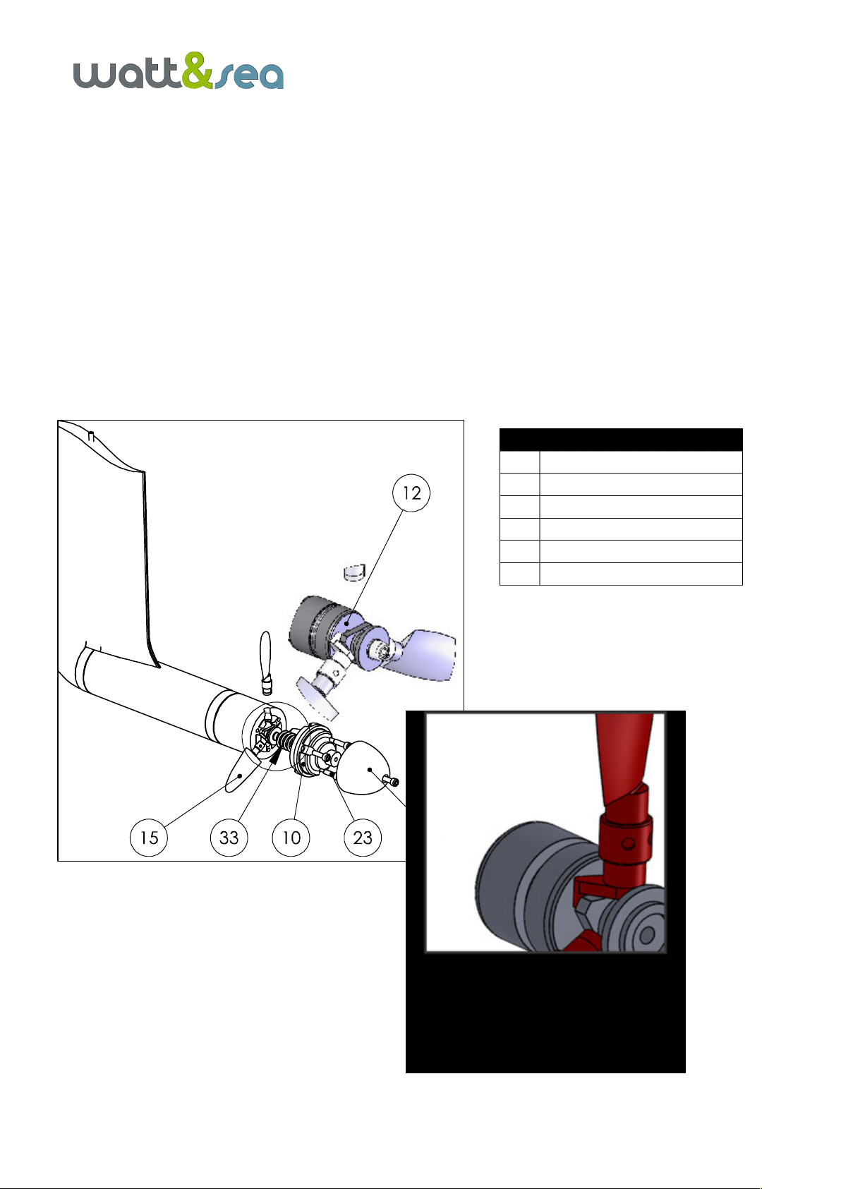
4.1. Installing the propeller blades
• Remove the propeller cone (11), then the propeller blades support (10); pay attention to the spacer
spring inside the shaft.
• Clip the blades into their respective slots in the hub. The mounting lug must be positioned behind the
piston triangle (12).
• Remount the propeller blades support, with a moderate torque on the 3 screws CHC M5. Then, remount
the cone with similar moderate torque on the CHC M5 screw. The blades must rotate freely inside their
slots.
Figure 2: Exploded view of the prop shaft
N
Description
10
Propeller blades support
11
Propeller cone
12
Piston
15
Propeller blades
23
Screw CHC M5x30 (4x)
33
Spacer spring

!
8
4.2. Placing the device on the transom
Correctly positioning the hydrogenerator is crucial for optimizing its performance.
The following criteria must be respected during the installation :
• Immersion depth:
The recommended depth between the surface and the propeller axis is 30cm (12 inches).
The machine comes with a 610mm (24 in) aluminium profile and with a lifting bracket schedule to be fitted on a
transom just upon the waterline.
The greater the depth, the farther the propeller will be from the wake of the hull, and the better the performance
of the hydrogenerator. However, the most important the lever arm is, the greater the force on the mountings and
during lifting will be.
For the boats of which the transom takes off while heeling, we recommend either a system to move the
hydrogenerator from portside to starboard, or to install 2 units.
• Flow quality:
The quality of water flow is a key element for obtaining satisfactory power output.
NOTE : Do not position the hydrogenerator directly in the wake of an appendage or too close
to a saildrive.
Wherever possible, position the hydrogenerator several inches to the side.
• • Linkage:
Provide a mechanical locking system of the device in a vertical position so that all the degrees of freedom are
blocked. In this way the device is less vulnerable in the event of flood water on the transom.

!
9
4.3. Installing the bracket on the transom
Depending on your boat's transom, its structure might need to be reinforced to take the stress on the mountings.
Phonic insulation also reduces vibrations.
WARNING : Due to the size of the lever arm, the maximum theoretical stress on the bracket's
fork mountings is estimated at around 300 kg. Your mounting system should be adapted
accordingly.
The bracket must be adapted to the 8 mm diameter fork mountings that are securely mounted onto the transom.
These fork mountings must be mounted in such a way as to compensate for any tilt of the transom. The diagram
below will help you to adapt the mountings to your boat.
N.B. : The leg must be vertical in the lowered position.
Figure 3 : Cradle dimensions
408,5
292,50
266,50
234,1
8,20
48
4 x
6,10
MM
MASSE:
A3
FEUILLE 1 SUR 1
ECHELLE:1:5
No. DE PLAN
TITRE:
REVISION
NE PAS CHANGER L'ECHELLE
MATERIAU:
DATE
SIGNATURE
NOM
CASSER LES
ANGLES VIFS
FINITION:
SAUF INDICATION CONTRAIRE:
LES COTES SONT EN MILLIMETRES
ETAT DE SURFACE:
TOLERANCES:
LINEAIRES:
ANGULAIRES:
QUAL.
FAB.
APPR.
VERIF.
AUTEUR
20131-002-001
ACIER C35
0.272 kg
B
!
10
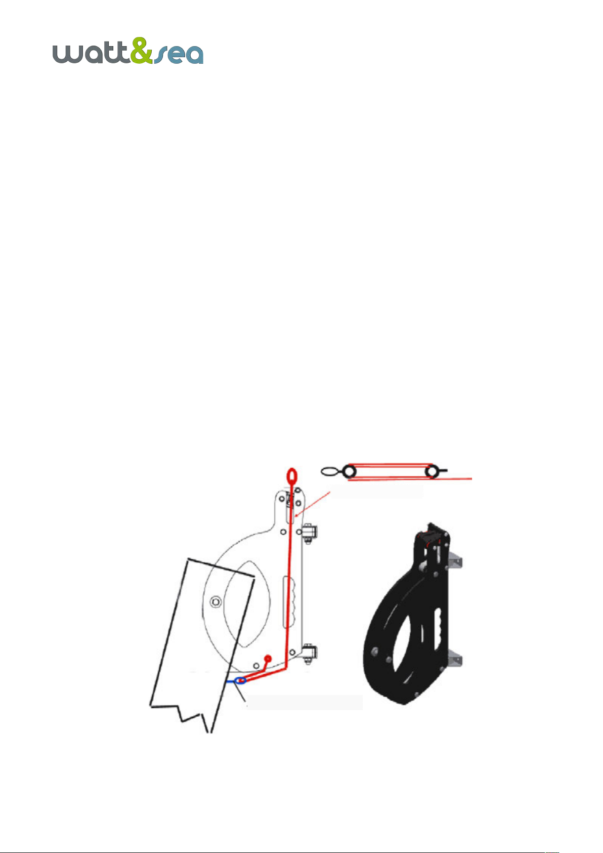
4.4. Rigging the immersion/lifting system
The hydrogenerator is supplied with a lifting bracket that functions in a similar way to the systems used on the
rudders. It facilitates access to the propeller when the device is lifted, for the removal of seaweed for example.
The lowering and lifting procedures are carried out using a hoist which is not included in the pack. The maximum
traction during lifting is around 40 kg. It is therefore recommended to rig a 6:1 hoist with a 6 mm diameter
sheathed line (hoist available in option at Watt&Sea).
To minimize the effort, it is advisable to install the low friction ring by tying a cow's hitch knot through the eyelet
located under the bracket.
• Assembly of the ring on the leg :
Pass the rope of the low friction ring through the hole of the leg located under the bracket and attach it with a
lark's head knot (see picture below)
• Assembly of the lowering rope :
Pass the rope successively :
-in the cam-cleat of the bracket
-in the two gudgeons of the bracket
-through the low friction ring
-in the hole of the lower gudgeon
-Finish the assembly by an eight-knot (see picture below)
The cleat integrated into the bracket is used to lock the lowering and lifting line. For permanent blocking, you can
use the locking pin.
Figure 4 : View of the lowering and lifting line
BOUT D’IMMERSION
LOWERING ROPE
ANNEAU FAIBLE FRICTION
LOW FRICTION RING

!
11
Figure 5 : Assembly of the lowering line using a low friction ring
N.B. : When the hydrogenerator is submerged, the leg should sit flush in the groove of the
gudgeon provided for this purpose. If this is not the case, the lateral support will be less
efficient, and this may result in mechanical damage.
It is also advisable to hold the lifting end in place using an elastic cord to prevent it from leaving the groove.
!
12
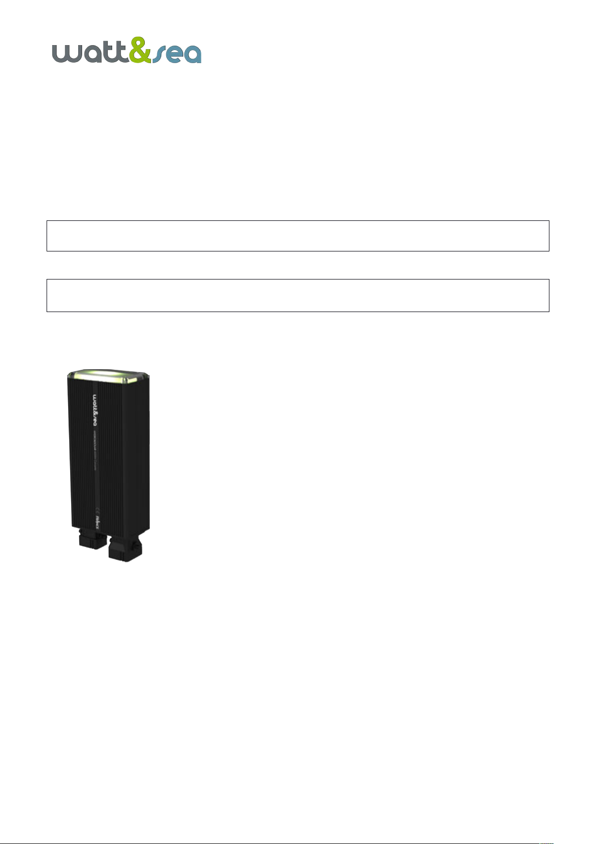
4.5. Mounting the electronic converter
The electronic converter is a box which is resistant to splashes and passive ventilation, guaranteeing long-term
protection even in humid environments.
The converter must nevertheless be installed inside the boat, preferably in the mechanical room in close proximity
to the batteries.
WARNING : WHEN RUNNING, THE CONVERTER CAN REACH VERY HIGH TEMPERATURES. AS
SUCH, ASSEMBLY SHOULD BE CARRIED OUT IN A VENTILATED SPACE.
NOTE : To ensure proper ventilation, the converter must be mounted on a vertical bulkhead,
with the ventilation grids in a vertical position.
As it is so light, the converter can be securely attached using the Velcro
provided.
• degrease the surface on which the converter will be installed
• remove the protective tabs of the strips of Velcro provided on the converter
• apply the quick-drying glue if the surface is very uneven (against plywood,
fibreglass ...)
• firmly attach the converter to the surface
!
13
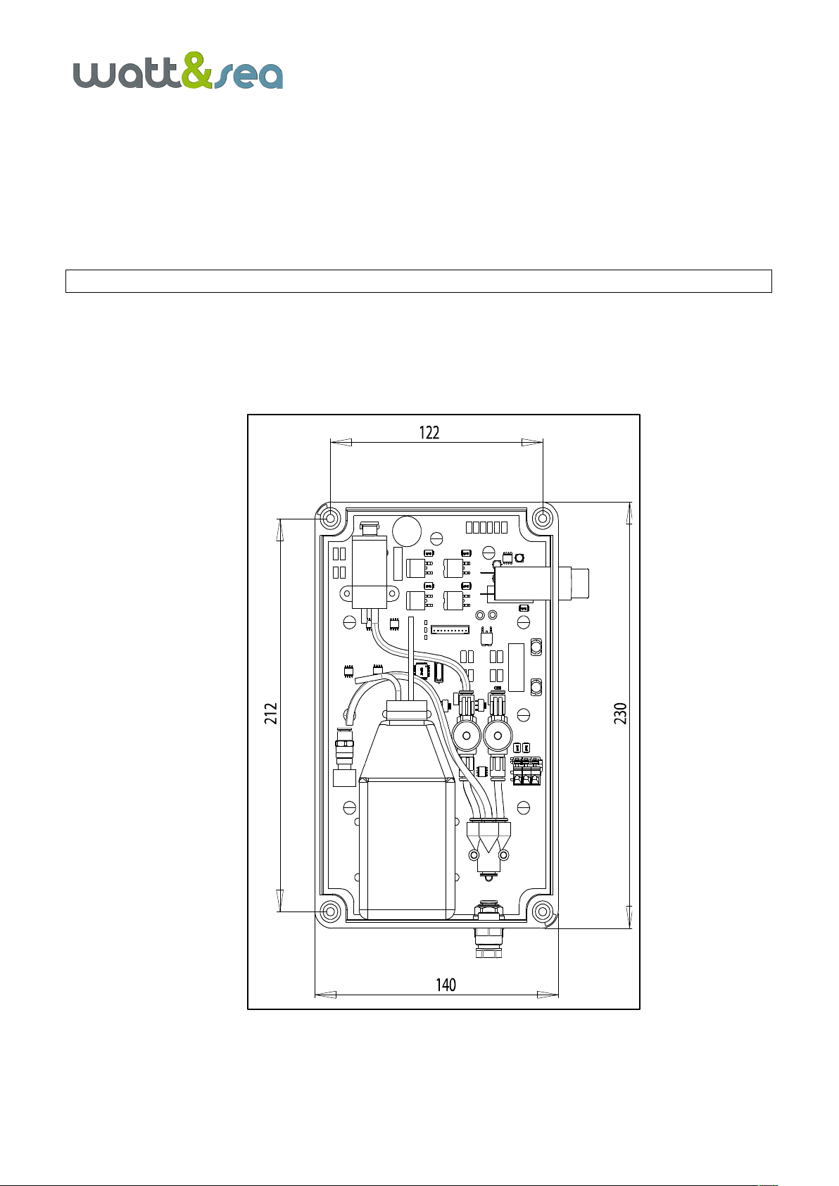
4.6. Mounting the hydraulic pump
The hydraulic pump is delivered in a waterproof casing that contains the electrical panel, the pump and it’s oil
tank. Two switches located on the side of the pump allow an easy manual control of the blade’s position.
The casing must be placed vertically, if possible near the converter and in an accessible location.
Note : The casing of the pump must be placed vertically.
Once the location is chosen, follow the procedure below:
• Pre-drill 4 holes using the template provided (212x122mm)
• Open the cover by removing the 4 screws
• Screw the waterproof casing into place, then re-place lid
Figure 6: Dimensions of hydraulic pump

!
14
5. ELECTRICAL INSTALLATION.
Recommendations regarding electric connections:
-Please consult local/national safety rules before installation.
-All electric cables must be carefully insulated. For maximum protection, cover the cables with electrical
cable sheaths.
WARNING: CONNECTIONS MUST BE INSPECTED REGULARLY TO DETECT ANY SIGNS OF
CORROSION AND CLEANED WHEN NECESSARY.
Figure 7: Wiring schematic
Figure 8: Phase converter wiring plan.
not used / non utilisé
(female contact / contact femelle)
(female contact / contact femelle)
(female contact / contact femelle)
(male contact / contact mâle)
not used / non utilisé
heat-shrinking tube
heat-shrinking tube
HYDROGENERATOR CONNECTOR
Phases : RED, ORANGE, BROWN (Rouge, Orange, Marron)
Not used : BLACK (Noir non utilisé)
SOLAR CONNECTOR
Positive : RED max 50V in open circuit (Rouge, max 50V)
Negative : BLACK common with battery negative (Noir)
Not used : ORANGE, BROWN (Orange, Marron non utilisés)
BATT #1 POSITIVE
POSITIF BATTERIE N°1
BATT #2 POSITIVE
POSITIF BATTERIE N°2
COMMON BATT NEGATIVE
NEGATIF COMMUN
40 rue Chef de Baie –17000 LA ROCHELLE –FRANCE
www.wattandsea.com
01-2019
CONVERTER CV-03
CONNECTIONS DIAGRAM
CONVERTISSEUR CV-03
SCHEMA DES CONNECTEURS
RS485 CONNECTOR
Positive Batt#1 : BROWN (! Unfused !)
Negative : BLACK
Data A : GREEN
Data B : GRAY
Hydraulic tube 6X4
3xphases cable
Negative
Positive
!
15
5.1. Three-phases wiring of the hydrogenerator
WARNING : ALWAYS PLACE THE HYDROGENERATOR IN THE LIFTED POSITION BEFORE
STARTING WORK ON IT.
The hydrogen generator has a short cable at the outlet, long enough to fit into the boat. This cable is
composed of three phases. If it is necessary to extend it, at least 3x1.5mm2 should be used.
Then connect the 3 phases to one of the supplied sockets without using the EARTH conductor (green/yellow).
There is no order to connect to the other conductors (brown, grey, black). For example, you
can use WAGO 222 connectors.
Connect this plug to the input labeled "HYDRO".
NOTE : The phase sequence is irrelevant. Therefore, there is no need to take into account
the color or numbering of the cables.
5.2. Using a solar panel
The converter has a second input for a solar panel. The maximum solar panel voltage must not exceed 50
VDC and current 12 Amperes. The minimum voltage at which the converter can start charging is 7.5 VDC.
When the hydrogen generator and solar panel produce at the same time, priority is given to the hydrogen
generator. As soon as it does not produce any more (stopped, anchorage...) the converter automatically
takes into account the load of the solar panel.
Connect the solar panel to the 2nd socket provided, respecting the following polarity:
SOLAR NEGATIVE : green/yellow
SOLAR POSITIVE (50 V max) : grey
Connect this plug to the input labeled "SOLAR".
CAUTION: OBSERVE THE POLARITY OF THE SOLAR PANEL
5.3 The converter to the batteries
The converter must be placed as close as possible to the batteries in order to minimize losses due to cable length.
The maximum recommended distance is 2 metres.
The batteries are connected to the converter via a solar connector.
The converter has an internal 2 output isolator that makes it possible to charge two battery units separately. The
2 battery banks must be at the same voltage.
The hydraulic pump is powered from output #2. If only one output from converter is used, you must use the #2 to
feed the pump. (see Fig. 8)
!
16
WARNING : RISK OF OVERLOADING AND FIRE. THE TWO BATTERY BANKS MUST BE THE SAME
TYPE AND HAVE THE SAME VOLTAGE.
WARNING : EACH BATTERY BANK MUST BE PROTECTED WITH A 50 AMP FUSE.
We recommend connecting the hydrogenerator's converter directly to the service battery bank. The converter will
monitor the batteries independently of the other on-board units, and will charge them when required.
N.B. : Proper operation on one external battery isolator is not guaranteed and may require
additional adjustment. Please contact your distributor.
WARNING : NEVER REVERSE THE POLARITY OF THE CONVERTER. THIS WILL LEAD TO THE
DESTRUCTION OF THE DEVICE.
©
PHOENIX CONTACT 2012-07-11 MNR 0125154 - 01 10488301
PV-CF-S6-16 (+)...
PV-CM-S6-16 (-)...
DE Einbauanweisung
EN Installation notes
FR Instructions d'installation
IT Istruzioni di installazione
ES Instrucciones de montaje
PT Instruções de instalação
RU
TR Montaj talimatı
ZH
PHOENIX CONTACT GmbH & Co. KG
32823 Blomberg, Germany
Phone +49-(0)5235-3-00
www.phoenixcontact.com
SUNCLIX-Photovoltaik-Steckverbinder
zum Einsatz in Photovoltaik-Anlagen
für
6...16mm
²-Solarkabel vom
Typ PV1-F
1 Sicherheitshinweise
WARNUNG: Die SUNCLIX-Steckverbin-
der dürfen ausschließlich durch elektro-
technisch unterwiesene Personen
angeschlossen werden.
WARNUNG: Stecken oder trennen Sie die
SUNCLIX-Steckverbinder niemals unter
Last.
ACHTUNG: Verwenden Sie die Steckver-
binder nur zusammen mit einem
6 ... 16 mm²-Solarkabel vom Typ PV1-F.
Nur mit diesem Kabel ist der sichere elekt-
rische Anschluss gewährleistet.
Beachten Sie beim Verlegen der Kabel die
Biegeradien, die der Hersteller vorgibt.
ACHTUNG: Verbinden Sie diese Steck-
verbinder nur mit anderen SUNCLIX-
Photovoltaik-Steckverbindern. Beachten
Sie bei dem Verbinden unbedingt die An-
gaben zu Nennspannung und Nennstrom.
Der kleinste gemeinsame Wert ist zuläs-
sig.
ACHTUNG: Schützen Sie die Steckver-
binder vor Feuchtigkeit und Schmutz.
–Tauchen Sie die Steckverbinder nicht un-
ter Wasser.
–Verlegen Sie den Stecker nicht direkt auf
der Dachhaut.
–Versehen Sie die Steckverbinder, die nicht
gesteckt sind, mit einer Schutzkappe (z. B.
PV-C PROTECTION CAP, Artikel-Nr.
1785430).
2Steckverbinder anschließen
Sie benötigen einen Schlitz-Schraubendreher mit
3-mm-breiter Klinge (z. B. SZF 1-0,6X3,5;
Artikel-Nr. 1204517).
2.1 Kabel anschließen (Bild
)
• Isolieren Sie das Kabel mit einem geeigneten
Werkzeug um 18 mm ab. Achten Sie darauf,
dabei keine Einzeldrähte abzuschneiden.
1Führen Sie die abisolierte Ader sorgfältig bis
zum Anschlag ein. Die Litzenenden müssen in
der Feder sichtbar sein.
2Schließen Sie die Feder. Stellen Sie sicher,
dass die Feder eingerastet ist.
3Schieben Sie den Einsatz in die Hülse.
4Ziehen Sie die Kabelverschraubung mit 3 Nm
an.
2.2 Steckverbinder zusammen fügen
•Führen Sie Stecker und Buchse zusammen.
Dabei rastet die Verbindung ein.
• Ziehen Sie an der Kupplung, um die korrekte
Verbindung zu prüfen.
3 Steckverbinder trennen (Bild
)
1Führen Sie den Schraubendreher ein, wie in
Bild gezeigt.
2Lassen Sie den Schraubendreher stecken und
trennen Sie Buchse und Stecker voneinander.
3.1 Kabel lösen (Bild
)
1Drehen Sie die Kabelverschraubung auf.
2Führen Sie den Schraubendreher an der in
Bild gezeigten Position ein.
3Hebeln Sie die Verbindung auf und ziehen Sie
Hülse und Einsatz auseinander.
4Öffnen Sie die Feder mit dem Schraubendre-
her.
5Entfernen Sie das Kabel.
4 Technische Daten
Umgebungstemperatur: -40 °C... +90 °C
Nennspannung: max. 1500 V DC
Nennstrom: 40 A (6 mm²), 50 A (10 mm²),
65 A (16 mm²)
Kabeldurchmesser: 5,5 ...10 mm
SUNCLIX photovoltaic I/O connector
for installation in photovoltaic systems
for
6...16
mm² solar cables, type PV1-F
1Safety notes
WARNING:The SUNCLIX plug-in connec-
tors may be connected only by trained
electricians.
WARNING:Never plug in or disconnect
the SUNCLIX plug-in connectors under
load.
NOTE: Use these plug-in connectors only
in combination with a 6 ... 16 mm² solar ca-
ble, type PV1-F. A safe, electrical connec-
tion is only possible with this cable.
When laying out the cable, observe the
bending radiuses that the manufacturer
specifies.
NOTE: Connect this plug-in connector
only with other SUNCLIX photovoltaic
plug-in connector. When making the con-
nections, be sure to observe the specifica-
tions on nominal voltage and nominal
current. The smallest common value is
permissible.
NOTE: Protect the plug-in connectors
from humidity and dirt.
– Do not immerse the plug-in connector in
water.
–Never lay out the plug directly on the roof-
ing.
–Attach a protective cap (e.g.
PV-C PROTECTION CAP, order number
1785430) to plug-in connectors that are
not plugged in.
2 Connecting connectors
You need a slot screwdriver with a 3-mm wide
blade (e.g. SZF 1-0.6X3.5; item no. 1204517).
2.1 Connecting the cable (Fig.
)
•Strip the cable by 18 mm with a suitable tool.
Make sure that no individual wires are cut off.
1Carefully insert the stripped wire all the way in.
The litz wire ends have to be visible in the
spring.
2Close the spring. Make sure that the spring is
snapped in.
3Push the insert into the sleeve.
4Tighten the cable gland to 3 Nm.
2.2 Assemble the connector
•Bring the plug and the socket together. The
connection snaps close thereby.
•Pull on the coupling to check the proper con-
nection.
3 Separating the connector (Fig
)
1Insert the screwdriver as shown in Fig. .
2Leave screwdriver inserted and disconnect the
plug and the socket from each other.
3.1 Loosen the cable (Fig. )
1Screw open the cable gland.
2Insert the screwdriver at the position shown in
Fig. .
3Pry the connection open and pull the sleeve
and the insert apart.
4Open the spring with the screwdriver.
5Remove the cable.
4 Technical data
Ambient temperature: -40 °C ... +90 °C
Nominal voltage: max. 1500 V DC
Nominal current: 40 A (6 mm²), 50 A (10 mm²),
65 A (16 mm²)
Cable diameter: 5,5 ...10 [mm]
Connecteur photovoltaïque SUNCLIX
destiné aux câbles pour système à
énergie solaire de 6 ... 16 mm²,
type PV1-F
1Consignes de sécurité
ATTENTION : Seules des personnes dû-
ment formées en électrotechnique sont
autorisées à installer les connecteurs
mâles SUNCLIX.
ATTENTION : Les connecteurs SUNCLIX
ne doivent jamais être connectés ni dé-
connectés en charge.
IMPORTANT : Utiliser ces connecteurs
uniquement avec des câbles pour sys-
tème à énergie solaire de 6 ... 16 mm² et
de type PV1-F. Seul ce câble garantit la
sécurité électrique du raccordement.
Lors de la pose du câble, respecter les
rayons de courbure prescrits par le fabri-
cant.
IMPORTANT : Raccorder ces connec-
teurs mâles uniquement avec d'autres
connecteurs photovoltaïques SUNCLIX.
Lors du raccordement, respecter impérati-
vement les valeurs données pour la ten-
sion nominale et pour l'intensité nominale.
Le plus petit dénominateur commun est
admis.
IMPORTANT : Protéger les connecteurs
mâles de l'humidité et de la saleté.
– Ne jamais plonger les connecteurs mâles
dans l'eau.
–Ne jamais poser directement le connec-
teur sur la peau du toit.
– Equiper les connecteurs mâles non enfi-
chés d'un capuchon de protection (par ex.
PV-C PROTECTION CAP, référence
1785430).
2 Raccordement du connecteur
Un tournevis à fente à lame large de 3 mm est re-
quis (par ex. SZF 1-0,6X3,5 ; référence1204517).
2.1 Raccordement du câble (Figure
)
•Dénuder le câble sur 18mm avec un outil ap-
proprié. Veiller à ne sectionner aucun fil du
câble.
1Introduire le fil dénudé avec prudence jusqu'en
butée. Les extrémités des torons doivent appa-
raître dans le « tiroir » à ressort.
2Refermer le « tiroir » à ressort. Vérifier qu'il est
bien encliqueté.
3Enfiler le raccord dans le manchon.
4Serrer le presse-étoupe à 3 Nm.
2.2 Assemblage du connecteur mâle
•Assembler le connecteur et le connecteur fe-
melle. Veiller à ce que la connexion s'encli-
quète.
•Exercer une traction des deux côtés du raccor-
dement pour en vérifier la solidité.
3 Déconnexion du connecteur mâle
(Figure
)
1Introduire un tournevis comme indiqué à la Fi-
gure .
2Laisser le tournevis en place et séparer le
connecteur mâle du connecteur femelle.
3.1 Séparation du câble (Figure
)
1Dévisser le raccord vissé du câble.
2Introduire le tournevis à l'emplacement indiqué
à la Figure .
3Soulever la connexion puis séparer le man-
chon du raccord.
4Ouvrir le « tiroir » à ressort avec le tournevis.
5Extraire le câble de la connexion.
4 Caractéristiques techniques
Température ambiante : -40 °C ... +90 °C
Tension nominale : 1500 V DC max.
Intensité nominale : 40 A (6 mm²), 50 A (10 mm²),
65 A (16 mm²)
Diamètre de câble : 5,5 ...10 mm
Connettore fotovoltaico SUNCLIX per
l'utilizzo in impianti fotovoltaici per cavi
solari da
6...16mm
² del tipo PV1-F
1 Avvertenze di sicurezza
AVVERTENZA: I connettori SUNCLIX de-
vono essere collegati solo da persone che
operano sotto la supervisione di elettricisti
specializzati.
AVVERTENZA: Collegare o scollegare i
connettori SUNCLIX soltanto in assenza di
carico.
IMPORTANTE: Utilizzare questi connetto-
ri soltanto insieme a un cavo solare da
6...16mm² del tipo PV1-F. Solo con que-
sto cavo si garantisce un collegamento
elettrico sicuro.
Per la posa del cavo rispettare i raggi di
curvatura prescritti dal produttore.
IMPORTANTE: Collegare questi connet-
tori soltanto con altri connettori fotovoltaici
SUNCLIX. Per il collegamento rispettare
assolutamente le indicazioni sulla tensio-
ne nominale e la corrente nominale. È per-
messo il più piccolo valore comune.
IMPORTANTE: Proteggere dalla polvere
e dall'umidità i connettori.
– Non immergere in acqua i connettori.
–Non posare il connettore direttamente sul
manto di copertura del tetto.
– Applicare un cappuccio di sicurezza
(ad es. PV-C PROTECTION CAP, codice
1785430) ai connettori non collegati.
2Connessione
È necessario un cacciavite per viti a taglio con una
punta larga 3 mm (ad es. SZF 1-0,6X3,5;
codice 1204517).
2.1 Collegamento del cavo (figura
)
•Spelare il cavo di 18 mm con un utensile adat-
to. Eseguendo questa operazione, fare atten-
zione a non tagliare i conduttori singoli.
1Inserire con cura il conduttore spelato fino a
battuta. Le estremità dei cavetti devono essere
visibili nell'elemento di bloccaggio a molla.
2Chiudere l'elemento di bloccaggio a molla. Ve-
rificare che scatti.
3Infilare l'inserto nel capocorda.
4Serrare la connessione a vite per cavo con una
coppia di 3 Nm.
2.2 Unione dei connettori
•Congiungere assieme connettore maschio e
connettore femmina. I connettori si innestano.
•Tirare il giunto per verificare che il collegamen-
to sia corretto.
3 Separazione dei connettori
(figura
)
1Inserire il cacciavite come indicato in figura .
2Lasciare inserito il cacciavite e scollegare il
connettore femmina dal connettore maschio.
3.1 Scollegamento del cavo (figura
)
1Svitare la connessione a vite per cavo.
2Inserire il cacciavite nella posizione indicata
nella figura .
3Fare leva sul collegamento e staccare il con-
nettore femmina dall'inserto.
4Aprire l'elemento di bloccaggio a molla con il
cacciavite.
5Rimuovere il cavo.
4Dati tecnici
Temperatura ambiente: -40 °C ... +90 °C
Tensione nominale: max. 1500 V DC.
Corrente nominale: 40 A (6 mm²), 50 A (10 mm²),
65 A (16 mm²)
Diametro cavo: 5,5 ...10 mm
1
2
3
3Nm
4
18
18
2
1
EnglishFrançaisItaliano Deutsch
©
PHOENIX CONTACT 2012-07-11 MNR 0125154 - 01 10488301
PV-CF-S6-16 (+)...
PV-CM-S6-16 (-)...
DE Einbauanweisung
EN Installation notes
FR Instructions d'installation
IT Istruzioni di installazione
ES Instrucciones de montaje
PT Instruções de instalação
RU
TR Montaj talimatı
ZH
PHOENIX CONTACT GmbH & Co. KG
32823 Blomberg, Germany
Phone +49-(0)5235-3-00
www.phoenixcontact.com
SUNCLIX-Photovoltaik-Steckverbinder
zum Einsatz in Photovoltaik-Anlagen
für
6...16mm
²-Solarkabel vom
Typ PV1-F
1 Sicherheitshinweise
WARNUNG: Die SUNCLIX-Steckverbin-
der dürfen ausschließlich durch elektro-
technisch unterwiesene Personen
angeschlossen werden.
WARNUNG: Stecken oder trennen Sie die
SUNCLIX-Steckverbinder niemals unter
Last.
ACHTUNG: Verwenden Sie die Steckver-
binder nur zusammen mit einem
6 ... 16 mm²-Solarkabel vom Typ PV1-F.
Nur mit diesem Kabel ist der sichere elekt-
rische Anschluss gewährleistet.
Beachten Sie beim Verlegen der Kabel die
Biegeradien, die der Hersteller vorgibt.
ACHTUNG: Verbinden Sie diese Steck-
verbinder nur mit anderen SUNCLIX-
Photovoltaik-Steckverbindern. Beachten
Sie bei dem Verbinden unbedingt die An-
gaben zu Nennspannung und Nennstrom.
Der kleinste gemeinsame Wert ist zuläs-
sig.
ACHTUNG: Schützen Sie die Steckver-
binder vor Feuchtigkeit und Schmutz.
–Tauchen Sie die Steckverbinder nicht un-
ter Wasser.
–Verlegen Sie den Stecker nicht direkt auf
der Dachhaut.
–Versehen Sie die Steckverbinder, die nicht
gesteckt sind, mit einer Schutzkappe (z. B.
PV-C PROTECTION CAP, Artikel-Nr.
1785430).
2Steckverbinder anschließen
Sie benötigen einen Schlitz-Schraubendreher mit
3-mm-breiter Klinge (z. B. SZF 1-0,6X3,5;
Artikel-Nr. 1204517).
2.1 Kabel anschließen (Bild )
• Isolieren Sie das Kabel mit einem geeigneten
Werkzeug um 18 mm ab. Achten Sie darauf,
dabei keine Einzeldrähte abzuschneiden.
1Führen Sie die abisolierte Ader sorgfältig bis
zum Anschlag ein. Die Litzenenden müssen in
der Feder sichtbar sein.
2Schließen Sie die Feder. Stellen Sie sicher,
dass die Feder eingerastet ist.
3Schieben Sie den Einsatz in die Hülse.
4Ziehen Sie die Kabelverschraubung mit 3 Nm
an.
2.2 Steckverbinder zusammen fügen
•Führen Sie Stecker und Buchse zusammen.
Dabei rastet die Verbindung ein.
• Ziehen Sie an der Kupplung, um die korrekte
Verbindung zu prüfen.
3 Steckverbinder trennen (Bild
)
1Führen Sie den Schraubendreher ein, wie in
Bild gezeigt.
2Lassen Sie den Schraubendreher stecken und
trennen Sie Buchse und Stecker voneinander.
3.1 Kabel lösen (Bild )
1Drehen Sie die Kabelverschraubung auf.
2Führen Sie den Schraubendreher an der in
Bild gezeigten Position ein.
3Hebeln Sie die Verbindung auf und ziehen Sie
Hülse und Einsatz auseinander.
4Öffnen Sie die Feder mit dem Schraubendre-
her.
5Entfernen Sie das Kabel.
4 Technische Daten
Umgebungstemperatur: -40 °C... +90 °C
Nennspannung: max. 1500 V DC
Nennstrom: 40 A (6 mm²), 50 A (10 mm²),
65 A (16 mm²)
Kabeldurchmesser: 5,5 ...10 mm
SUNCLIX photovoltaic I/O connector
for installation in photovoltaic systems
for
6...16
mm² solar cables, type PV1-F
1Safety notes
WARNING:The SUNCLIX plug-in connec-
tors may be connected only by trained
electricians.
WARNING:Never plug in or disconnect
the SUNCLIX plug-in connectors under
load.
NOTE: Use these plug-in connectors only
in combination with a 6 ... 16 mm² solar ca-
ble, type PV1-F. A safe, electrical connec-
tion is only possible with this cable.
When laying out the cable, observe the
bending radiuses that the manufacturer
specifies.
NOTE: Connect this plug-in connector
only with other SUNCLIX photovoltaic
plug-in connector. When making the con-
nections, be sure to observe the specifica-
tions on nominal voltage and nominal
current. The smallest common value is
permissible.
NOTE: Protect the plug-in connectors
from humidity and dirt.
– Do not immerse the plug-in connector in
water.
–Never lay out the plug directly on the roof-
ing.
–Attach a protective cap (e.g.
PV-C PROTECTION CAP, order number
1785430) to plug-in connectors that are
not plugged in.
2 Connecting connectors
You need a slot screwdriver with a 3-mm wide
blade (e.g. SZF 1-0.6X3.5; item no. 1204517).
2.1 Connecting the cable (Fig. )
•Strip the cable by 18 mm with a suitable tool.
Make sure that no individual wires are cut off.
1Carefully insert the stripped wire all the way in.
The litz wire ends have to be visible in the
spring.
2Close the spring. Make sure that the spring is
snapped in.
3Push the insert into the sleeve.
4Tighten the cable gland to 3 Nm.
2.2 Assemble the connector
•Bring the plug and the socket together. The
connection snaps close thereby.
•Pull on the coupling to check the proper con-
nection.
3 Separating the connector (Fig
)
1Insert the screwdriver as shown in Fig. .
2Leave screwdriver inserted and disconnect the
plug and the socket from each other.
3.1 Loosen the cable (Fig. )
1Screw open the cable gland.
2Insert the screwdriver at the position shown in
Fig. .
3Pry the connection open and pull the sleeve
and the insert apart.
4Open the spring with the screwdriver.
5Remove the cable.
4 Technical data
Ambient temperature: -40 °C ... +90 °C
Nominal voltage: max. 1500 V DC
Nominal current: 40 A (6 mm²), 50 A (10 mm²),
65 A (16 mm²)
Cable diameter: 5,5 ...10 [mm]
Connecteur photovoltaïque SUNCLIX
destiné aux câbles pour système à
énergie solaire de 6 ... 16 mm²,
type PV1-F
1Consignes de sécurité
ATTENTION : Seules des personnes dû-
ment formées en électrotechnique sont
autorisées à installer les connecteurs
mâles SUNCLIX.
ATTENTION : Les connecteurs SUNCLIX
ne doivent jamais être connectés ni dé-
connectés en charge.
IMPORTANT : Utiliser ces connecteurs
uniquement avec des câbles pour sys-
tème à énergie solaire de 6 ... 16 mm² et
de type PV1-F. Seul ce câble garantit la
sécurité électrique du raccordement.
Lors de la pose du câble, respecter les
rayons de courbure prescrits par le fabri-
cant.
IMPORTANT : Raccorder ces connec-
teurs mâles uniquement avec d'autres
connecteurs photovoltaïques SUNCLIX.
Lors du raccordement, respecter impérati-
vement les valeurs données pour la ten-
sion nominale et pour l'intensité nominale.
Le plus petit dénominateur commun est
admis.
IMPORTANT : Protéger les connecteurs
mâles de l'humidité et de la saleté.
– Ne jamais plonger les connecteurs mâles
dans l'eau.
–Ne jamais poser directement le connec-
teur sur la peau du toit.
– Equiper les connecteurs mâles non enfi-
chés d'un capuchon de protection (par ex.
PV-C PROTECTION CAP, référence
1785430).
2 Raccordement du connecteur
Un tournevis à fente à lame large de 3 mm est re-
quis (par ex. SZF 1-0,6X3,5 ; référence1204517).
2.1 Raccordement du câble (Figure )
•Dénuder le câble sur 18mm avec un outil ap-
proprié. Veiller à ne sectionner aucun fil du
câble.
1Introduire le fil dénudé avec prudence jusqu'en
butée. Les extrémités des torons doivent appa-
raître dans le « tiroir » à ressort.
2Refermer le « tiroir » à ressort. Vérifier qu'il est
bien encliqueté.
3Enfiler le raccord dans le manchon.
4Serrer le presse-étoupe à 3 Nm.
2.2 Assemblage du connecteur mâle
•Assembler le connecteur et le connecteur fe-
melle. Veiller à ce que la connexion s'encli-
quète.
•Exercer une traction des deux côtés du raccor-
dement pour en vérifier la solidité.
3 Déconnexion du connecteur mâle
(Figure
)
1Introduire un tournevis comme indiqué à la Fi-
gure .
2Laisser le tournevis en place et séparer le
connecteur mâle du connecteur femelle.
3.1 Séparation du câble (Figure )
1Dévisser le raccord vissé du câble.
2Introduire le tournevis à l'emplacement indiqué
à la Figure .
3Soulever la connexion puis séparer le man-
chon du raccord.
4Ouvrir le « tiroir » à ressort avec le tournevis.
5Extraire le câble de la connexion.
4 Caractéristiques techniques
Température ambiante : -40 °C ... +90 °C
Tension nominale : 1500 V DC max.
Intensité nominale : 40 A (6 mm²), 50 A (10 mm²),
65 A (16 mm²)
Diamètre de câble : 5,5 ...10 mm
Connettore fotovoltaico SUNCLIX per
l'utilizzo in impianti fotovoltaici per cavi
solari da
6...16mm
² del tipo PV1-F
1 Avvertenze di sicurezza
AVVERTENZA: I connettori SUNCLIX de-
vono essere collegati solo da persone che
operano sotto la supervisione di elettricisti
specializzati.
AVVERTENZA: Collegare o scollegare i
connettori SUNCLIX soltanto in assenza di
carico.
IMPORTANTE: Utilizzare questi connetto-
ri soltanto insieme a un cavo solare da
6...16mm² del tipo PV1-F. Solo con que-
sto cavo si garantisce un collegamento
elettrico sicuro.
Per la posa del cavo rispettare i raggi di
curvatura prescritti dal produttore.
IMPORTANTE: Collegare questi connet-
tori soltanto con altri connettori fotovoltaici
SUNCLIX. Per il collegamento rispettare
assolutamente le indicazioni sulla tensio-
ne nominale e la corrente nominale. È per-
messo il più piccolo valore comune.
IMPORTANTE: Proteggere dalla polvere
e dall'umidità i connettori.
– Non immergere in acqua i connettori.
–Non posare il connettore direttamente sul
manto di copertura del tetto.
– Applicare un cappuccio di sicurezza
(ad es. PV-C PROTECTION CAP, codice
1785430) ai connettori non collegati.
2Connessione
È necessario un cacciavite per viti a taglio con una
punta larga 3 mm (ad es. SZF 1-0,6X3,5;
codice 1204517).
2.1 Collegamento del cavo (figura )
•Spelare il cavo di 18 mm con un utensile adat-
to. Eseguendo questa operazione, fare atten-
zione a non tagliare i conduttori singoli.
1Inserire con cura il conduttore spelato fino a
battuta. Le estremità dei cavetti devono essere
visibili nell'elemento di bloccaggio a molla.
2Chiudere l'elemento di bloccaggio a molla. Ve-
rificare che scatti.
3Infilare l'inserto nel capocorda.
4Serrare la connessione a vite per cavo con una
coppia di 3 Nm.
2.2 Unione dei connettori
•Congiungere assieme connettore maschio e
connettore femmina. I connettori si innestano.
•Tirare il giunto per verificare che il collegamen-
to sia corretto.
3 Separazione dei connettori
(figura
)
1Inserire il cacciavite come indicato in figura .
2Lasciare inserito il cacciavite e scollegare il
connettore femmina dal connettore maschio.
3.1 Scollegamento del cavo (figura )
1Svitare la connessione a vite per cavo.
2Inserire il cacciavite nella posizione indicata
nella figura .
3Fare leva sul collegamento e staccare il con-
nettore femmina dall'inserto.
4Aprire l'elemento di bloccaggio a molla con il
cacciavite.
5Rimuovere il cavo.
4Dati tecnici
Temperatura ambiente: -40 °C ... +90 °C
Tensione nominale: max. 1500 V DC.
Corrente nominale: 40 A (6 mm²), 50 A (10 mm²),
65 A (16 mm²)
Diametro cavo: 5,5 ...10 mm
1
2
3
3Nm
4
18
18
2
1
EnglishFrançaisItaliano Deutsch

!
17
Figure 9: battery connectors manual
5.3. Connecting the hydraulic pump to the batteries
The hydraulic pump must be placed in an accessible position, with good access to all the switches and the oil
gauge.
The pump is powered directly through the provided connector, from the output#2. If only one of the two available
converter outputs is used, the #2 must be used.
Check the correct functioning of the device by putting it in “manual” mode, and activate “pump”. The pump must
turn under the manual impulse.
WARNING : DO NOT RUN THE PUMP DRY IN A PROLONGED WAY AS LONG AS THE PUMP IS
NOT FILL IN OF OIL.
5.4. Interpretation of the converter’s Leds
-When the converter is not charging, the battery voltage is indicated by a pulse of color which changes from
green (12.8 V) to red (11.5 V).
-When the converter is charging, the output power is indicated by a constant color which changes from violet to
blue (120W), to light blue (240W) and finally to white (480W).
© PHOENIX CONTACT 2012-07-11 MNR 0125154 - 01 10488301
PV-CF-S6-16 (+)...
PV-CM-S6-16 (-)...
DE Einbauanweisung
EN Installation notes
FR Instructions d'installation
IT Istruzioni di installazione
ES Instrucciones de montaje
PT Instruções de instalação
RU
TR Montaj talimatı
ZH
PHOENIX CONTACT GmbH & Co. KG
32823 Blomberg, Germany
Phone +49-(0)5235-3-00
www.phoenixcontact.com
SUNCLIX-Photovoltaik-Steckverbinder
zum Einsatz in Photovoltaik-Anlagen
für
6...16mm
²-Solarkabel vom
Typ PV1-F
1 Sicherheitshinweise
WARNUNG: Die SUNCLIX-Steckverbin-
der dürfen ausschließlich durch elektro-
technisch unterwiesene Personen
angeschlossen werden.
WARNUNG: Stecken oder trennen Sie die
SUNCLIX-Steckverbinder niemals unter
Last.
ACHTUNG: Verwenden Sie die Steckver-
binder nur zusammen mit einem
6 ... 16 mm²-Solarkabel vom Typ PV1-F.
Nur mit diesem Kabel ist der sichere elekt-
rische Anschluss gewährleistet.
Beachten Sie beim Verlegen der Kabel die
Biegeradien, die der Hersteller vorgibt.
ACHTUNG: Verbinden Sie diese Steck-
verbinder nur mit anderen SUNCLIX-
Photovoltaik-Steckverbindern. Beachten
Sie bei dem Verbinden unbedingt die An-
gaben zu Nennspannung und Nennstrom.
Der kleinste gemeinsame Wert ist zuläs-
sig.
ACHTUNG: Schützen Sie die Steckver-
binder vor Feuchtigkeit und Schmutz.
–Tauchen Sie die Steckverbinder nicht un-
ter Wasser.
–Verlegen Sie den Stecker nicht direkt auf
der Dachhaut.
–Versehen Sie die Steckverbinder, die nicht
gesteckt sind, mit einer Schutzkappe (z. B.
PV-C PROTECTION CAP, Artikel-Nr.
1785430).
2Steckverbinder anschließen
Sie benötigen einen Schlitz-Schraubendreher mit
3-mm-breiter Klinge (z. B. SZF 1-0,6X3,5;
Artikel-Nr. 1204517).
2.1 Kabel anschließen (Bild )
• Isolieren Sie das Kabel mit einem geeigneten
Werkzeug um 18 mm ab. Achten Sie darauf,
dabei keine Einzeldrähte abzuschneiden.
1Führen Sie die abisolierte Ader sorgfältig bis
zum Anschlag ein. Die Litzenenden müssen in
der Feder sichtbar sein.
2Schließen Sie die Feder. Stellen Sie sicher,
dass die Feder eingerastet ist.
3Schieben Sie den Einsatz in die Hülse.
4Ziehen Sie die Kabelverschraubung mit 3 Nm
an.
2.2 Steckverbinder zusammen fügen
•Führen Sie Stecker und Buchse zusammen.
Dabei rastet die Verbindung ein.
• Ziehen Sie an der Kupplung, um die korrekte
Verbindung zu prüfen.
3 Steckverbinder trennen (Bild )
1Führen Sie den Schraubendreher ein, wie in
Bild gezeigt.
2Lassen Sie den Schraubendreher stecken und
trennen Sie Buchse und Stecker voneinander.
3.1 Kabel lösen (Bild )
1Drehen Sie die Kabelverschraubung auf.
2Führen Sie den Schraubendreher an der in
Bild gezeigten Position ein.
3Hebeln Sie die Verbindung auf und ziehen Sie
Hülse und Einsatz auseinander.
4Öffnen Sie die Feder mit dem Schraubendre-
her.
5Entfernen Sie das Kabel.
4 Technische Daten
Umgebungstemperatur: -40 °C... +90 °C
Nennspannung: max. 1500 V DC
Nennstrom: 40 A (6 mm²), 50 A (10 mm²),
65 A (16 mm²)
Kabeldurchmesser: 5,5 ...10 mm
SUNCLIX photovoltaic I/O connector
for installation in photovoltaic systems
for
6...16
mm² solar cables, type PV1-F
1Safety notes
WARNING:The SUNCLIX plug-in connec-
tors may be connected only by trained
electricians.
WARNING:Never plug in or disconnect
the SUNCLIX plug-in connectors under
load.
NOTE: Use these plug-in connectors only
in combination with a 6 ... 16 mm² solar ca-
ble, type PV1-F. A safe, electrical connec-
tion is only possible with this cable.
When laying out the cable, observe the
bending radiuses that the manufacturer
specifies.
NOTE: Connect this plug-in connector
only with other SUNCLIX photovoltaic
plug-in connector. When making the con-
nections, be sure to observe the specifica-
tions on nominal voltage and nominal
current. The smallest common value is
permissible.
NOTE: Protect the plug-in connectors
from humidity and dirt.
– Do not immerse the plug-in connector in
water.
–Never lay out the plug directly on the roof-
ing.
–Attach a protective cap (e.g.
PV-C PROTECTION CAP, order number
1785430) to plug-in connectors that are
not plugged in.
2 Connecting connectors
You need a slot screwdriver with a 3-mm wide
blade (e.g. SZF 1-0.6X3.5; item no. 1204517).
2.1 Connecting the cable (Fig. )
•Strip the cable by 18 mm with a suitable tool.
Make sure that no individual wires are cut off.
1Carefully insert the stripped wire all the way in.
The litz wire ends have to be visible in the
spring.
2Close the spring. Make sure that the spring is
snapped in.
3Push the insert into the sleeve.
4Tighten the cable gland to 3 Nm.
2.2 Assemble the connector
•Bring the plug and the socket together. The
connection snaps close thereby.
•Pull on the coupling to check the proper con-
nection.
3 Separating the connector (Fig )
1Insert the screwdriver as shown in Fig. .
2Leave screwdriver inserted and disconnect the
plug and the socket from each other.
3.1 Loosen the cable (Fig. )
1Screw open the cable gland.
2Insert the screwdriver at the position shown in
Fig. .
3Pry the connection open and pull the sleeve
and the insert apart.
4Open the spring with the screwdriver.
5Remove the cable.
4 Technical data
Ambient temperature: -40 °C ... +90 °C
Nominal voltage: max. 1500 V DC
Nominal current: 40 A (6 mm²), 50 A (10 mm²),
65 A (16 mm²)
Cable diameter: 5,5 ...10 [mm]
Connecteur photovoltaïque SUNCLIX
destiné aux câbles pour système à
énergie solaire de 6 ... 16 mm²,
type PV1-F
1Consignes de sécurité
ATTENTION : Seules des personnes dû-
ment formées en électrotechnique sont
autorisées à installer les connecteurs
mâles SUNCLIX.
ATTENTION : Les connecteurs SUNCLIX
ne doivent jamais être connectés ni dé-
connectés en charge.
IMPORTANT : Utiliser ces connecteurs
uniquement avec des câbles pour sys-
tème à énergie solaire de 6 ... 16 mm² et
de type PV1-F. Seul ce câble garantit la
sécurité électrique du raccordement.
Lors de la pose du câble, respecter les
rayons de courbure prescrits par le fabri-
cant.
IMPORTANT : Raccorder ces connec-
teurs mâles uniquement avec d'autres
connecteurs photovoltaïques SUNCLIX.
Lors du raccordement, respecter impérati-
vement les valeurs données pour la ten-
sion nominale et pour l'intensité nominale.
Le plus petit dénominateur commun est
admis.
IMPORTANT : Protéger les connecteurs
mâles de l'humidité et de la saleté.
– Ne jamais plonger les connecteurs mâles
dans l'eau.
–Ne jamais poser directement le connec-
teur sur la peau du toit.
– Equiper les connecteurs mâles non enfi-
chés d'un capuchon de protection (par ex.
PV-C PROTECTION CAP, référence
1785430).
2 Raccordement du connecteur
Un tournevis à fente à lame large de 3 mm est re-
quis (par ex. SZF 1-0,6X3,5 ; référence1204517).
2.1 Raccordement du câble (Figure )
•Dénuder le câble sur 18mm avec un outil ap-
proprié. Veiller à ne sectionner aucun fil du
câble.
1Introduire le fil dénudé avec prudence jusqu'en
butée. Les extrémités des torons doivent appa-
raître dans le « tiroir » à ressort.
2Refermer le « tiroir » à ressort. Vérifier qu'il est
bien encliqueté.
3Enfiler le raccord dans le manchon.
4Serrer le presse-étoupe à 3 Nm.
2.2 Assemblage du connecteur mâle
•Assembler le connecteur et le connecteur fe-
melle. Veiller à ce que la connexion s'encli-
quète.
•Exercer une traction des deux côtés du raccor-
dement pour en vérifier la solidité.
3 Déconnexion du connecteur mâle
(Figure )
1Introduire un tournevis comme indiqué à la Fi-
gure .
2Laisser le tournevis en place et séparer le
connecteur mâle du connecteur femelle.
3.1 Séparation du câble (Figure )
1Dévisser le raccord vissé du câble.
2Introduire le tournevis à l'emplacement indiqué
à la Figure .
3Soulever la connexion puis séparer le man-
chon du raccord.
4Ouvrir le « tiroir » à ressort avec le tournevis.
5Extraire le câble de la connexion.
4 Caractéristiques techniques
Température ambiante : -40 °C ... +90 °C
Tension nominale : 1500 V DC max.
Intensité nominale : 40 A (6 mm²), 50 A (10 mm²),
65 A (16 mm²)
Diamètre de câble : 5,5 ...10 mm
Connettore fotovoltaico SUNCLIX per
l'utilizzo in impianti fotovoltaici per cavi
solari da
6...16mm
² del tipo PV1-F
1 Avvertenze di sicurezza
AVVERTENZA: I connettori SUNCLIX de-
vono essere collegati solo da persone che
operano sotto la supervisione di elettricisti
specializzati.
AVVERTENZA: Collegare o scollegare i
connettori SUNCLIX soltanto in assenza di
carico.
IMPORTANTE: Utilizzare questi connetto-
ri soltanto insieme a un cavo solare da
6...16mm² del tipo PV1-F. Solo con que-
sto cavo si garantisce un collegamento
elettrico sicuro.
Per la posa del cavo rispettare i raggi di
curvatura prescritti dal produttore.
IMPORTANTE: Collegare questi connet-
tori soltanto con altri connettori fotovoltaici
SUNCLIX. Per il collegamento rispettare
assolutamente le indicazioni sulla tensio-
ne nominale e la corrente nominale. È per-
messo il più piccolo valore comune.
IMPORTANTE: Proteggere dalla polvere
e dall'umidità i connettori.
– Non immergere in acqua i connettori.
–Non posare il connettore direttamente sul
manto di copertura del tetto.
– Applicare un cappuccio di sicurezza
(ad es. PV-C PROTECTION CAP, codice
1785430) ai connettori non collegati.
2Connessione
È necessario un cacciavite per viti a taglio con una
punta larga 3 mm (ad es. SZF 1-0,6X3,5;
codice 1204517).
2.1 Collegamento del cavo (figura )
•Spelare il cavo di 18 mm con un utensile adat-
to. Eseguendo questa operazione, fare atten-
zione a non tagliare i conduttori singoli.
1Inserire con cura il conduttore spelato fino a
battuta. Le estremità dei cavetti devono essere
visibili nell'elemento di bloccaggio a molla.
2Chiudere l'elemento di bloccaggio a molla. Ve-
rificare che scatti.
3Infilare l'inserto nel capocorda.
4Serrare la connessione a vite per cavo con una
coppia di 3 Nm.
2.2 Unione dei connettori
•Congiungere assieme connettore maschio e
connettore femmina. I connettori si innestano.
•Tirare il giunto per verificare che il collegamen-
to sia corretto.
3 Separazione dei connettori
(figura )
1Inserire il cacciavite come indicato in figura .
2Lasciare inserito il cacciavite e scollegare il
connettore femmina dal connettore maschio.
3.1 Scollegamento del cavo (figura )
1Svitare la connessione a vite per cavo.
2Inserire il cacciavite nella posizione indicata
nella figura .
3Fare leva sul collegamento e staccare il con-
nettore femmina dall'inserto.
4Aprire l'elemento di bloccaggio a molla con il
cacciavite.
5Rimuovere il cavo.
4Dati tecnici
Temperatura ambiente: -40 °C ... +90 °C
Tensione nominale: max. 1500 V DC.
Corrente nominale: 40 A (6 mm²), 50 A (10 mm²),
65 A (16 mm²)
Diametro cavo: 5,5 ...10 mm
1
2
3
3Nm
4
18
18
2
1
EnglishFrançaisItaliano Deutsch

!
18
-Green or red colored flashes may overlay the display of the constant color to indicate statuses or anomalies :
SITUATION
VISUAL
COMMENTS
Absorption voltage reached
1 brief green flash every 5 seconds
The battery is full (absorption voltage =14.3 V
/ 28.6 V)
Floating voltage maintained
1 long green flash every 5 seconds
The battery is kept at 100% (floating voltage =
13.8 V / 27.6 V)
Overheating
1 red flash every 5 seconds
The maximum box temperature has been
reached
Generator anomaly
2 red flashes every 5 seconds
The hydrogenerator's connection is defective
Overvoltage at input
3 red flashes every 5 seconds
The solar panel or the hydrogenerator are
applying a voltage that is too high
Another anomaly
4 red flashes every 5 seconds
Contact your distributor
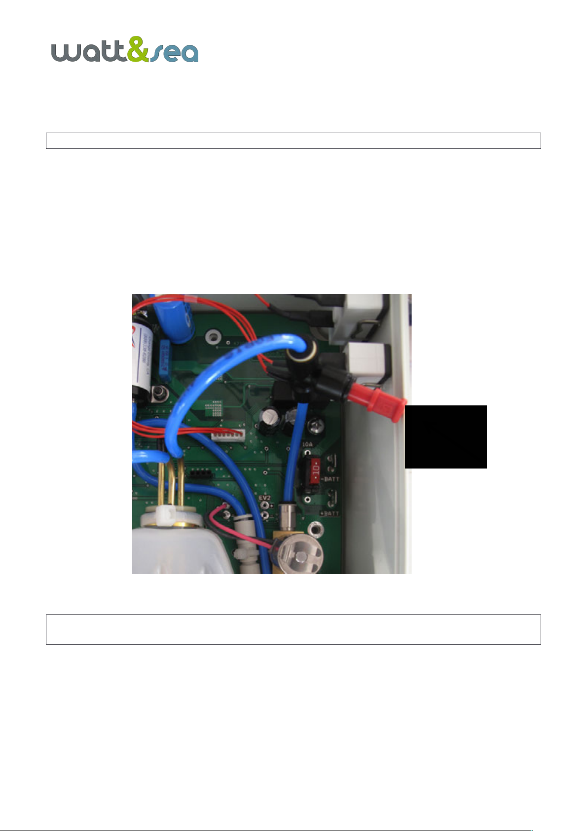
5.5. Interpretation of the hydraulic pump Leds
The hydraulic pump is equipped with several Led’s to indicate the system status :
-1 green Led as a power indicator (ON)
-1 red Led as an error communication indicator (ERR)
-1 green Led (RCV) to indicate data reception 3 times per second
-1 8-Leds Bargraph on the right to indicate the pressure inside the system, measured in Bars.
At high speed there should be 4-8 Bars. At low speed, there should be between 0 and 4 Bars.
Figure 10: Pump running
ON ERR RCV BARGRAPH (here : pressure is 3 Bars)
!
19
6. HYDRAULIC INSTALLATION
The hydraulic pump controls the pitch of the hydrogenerator blades.
The pump is designed to be matched to a polyamide tubing, exterior diameter of 6mm (~1/4“) (for example
LEGRIS 1025 P06 01).
In order to connect multiple hydrogenerators to the same pump, you must use a T-junction, diameter 6mm (for
example LEGRIS 3104 06 00)
The quick-release couplings can be used without tools. First, depressurize the circuit, then push the ring in and
slide the tube out. The tube must slide out easily.
Figure 11: Disconnecting the quick-release couplings (© LEGRIS)
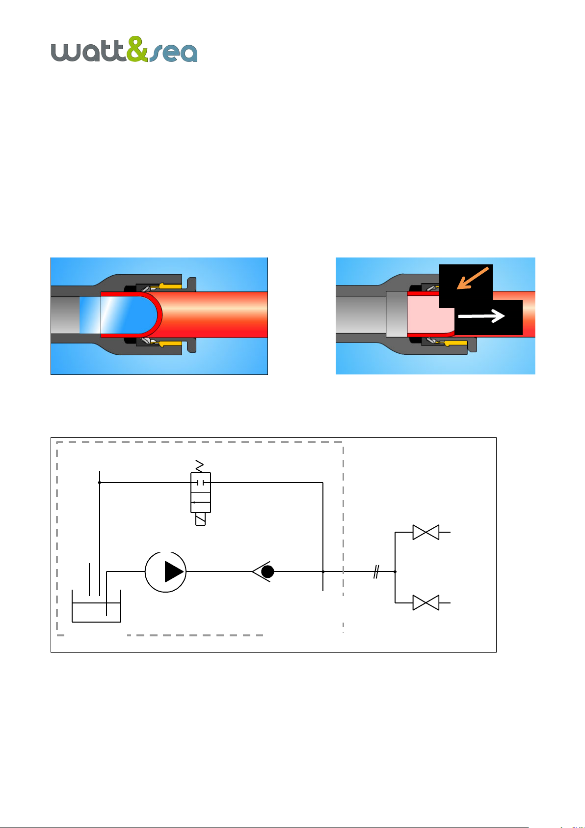
The pump housing contains a hydraulic micro-pump, a check-valve, a solenoid and a digital pressure gauge
Figure 12: Hydraulic circuit blueprint
HYDRO 1
HYDRO 2
capteur
pression
embout de
remplissage
réservoir
électrovanne
pompe clapet
COFFRET POMPE
solenoid
check valve
pump
pressure
sensor
filling valve
PUMP BOX
oil tank
!
20
6.1. Connecting the hydraulic circuit
Thread the hydraulic tubing from the transom to the pump.
Connect the pump to the circuit with the quick-release couplings located on the lower section of the housing.
Note : At this point, do not connect the hydrogenerators
6.2. Filling the oil tank and bleeding the circuit
Place a bucket to collect the oil that will be drained during the bleeding process.
Fill the oil tank with mineral oil (low viscosity type FUCHS Renolin Extra 22 S). This tank has a capacity maximum
of 300 mL.
To fill the tank, remove the filler cap and use a large caliber syringe.
When the tank is full, bleed the circuit using switch in manual and “pump” mode (maintain the “pump” switch
under pressure).
Figure 13: Oil filler cap
When you have finished bleeding the circuit, you can connect the hydrogenerators and top up the oil level.
Fill the oil tank to ¾capacity, in order to leave a margin for the good functioning of the
device during operation.
Verify in manual mode that the blades rotate and adjust correctly when following the preset commands.
If the blades are not moving, the hub screws might be too tighted or blades could be not correctly mounted.
Cap
Table of contents
Popular Boating Equipment manuals by other brands


Raymarine
Raymarine A series Installation and operation instructions

C. E. Smith
C. E. Smith 52100 installation instructions

Wichard
Wichard PROFURL MK 1R installation manual

Defender
Defender IsoBoost 60 SST Installation instructions & owner's manual

Power-Pole
Power-Pole Blade installation manual

Scanstrut
Scanstrut Scanpod SPR-1i-AM installation instructions

Ultraflex
Ultraflex T93ZT Installation and maintenance manual

ShoreStation
ShoreStation SSV30108EAS manual

Vetus
Vetus BTKIT Installation instructions and owner's manual

SLEIPNER MOTOR AS
SLEIPNER MOTOR AS Side-Power Series installation manual

Gumotex
Gumotex SEAWAVE user guide

monster tower
monster tower HS1 Installation instructions and owner's manual