Engel MT35F-U1D-P User manual

MODEL (Digital display type) :
MT35F-U1D-P 0642 032 0310
MT45F-U1D-P 0642 042 0R40
MT45F-U1CD-P 0642 042 1R00
2020.12
#3
SERVICE MANUAL
●FOR REFRIGERATOR USERS
・Failing to service properly may result in poor reliability of the refrigerator.
・Read this booklet carefully and perform servicing with great care.
・
●FOR SAFETY OF YOURSELF
・
●SAFETY SYMBOLS
・The following warning labels in this booklet indicate precautions for service work.
Comply with what each symbol indicates whenever it appears.
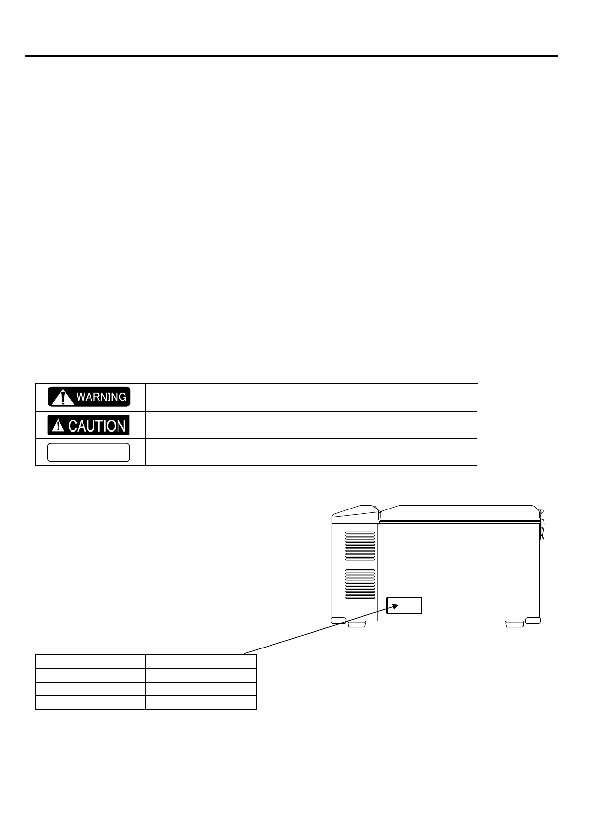
●REFRIGERATOR CODE NUMBERS
・This manual is compatible with described model in below.
Please check refrigerator model name and number in lable .
(Lable place as picture)
NUMBER MODEL NAME
0642 032 0310 MT35F-U1D-P
0642 042 0R40 MT45F-U1D-P
0642 042 1R00 MT45F-U1CD-P
To secure safe and correct servicing, read this manual thoroughly in advance and check
if there are protective equipment and appropriate tools and service parts ready as well
as technical skills necessary to perform servicing.
May lead to death or serious injury if failed to comply with this
precaution
May lead to injury if failed to comply with this precaution
Lead to failure of the refrigerator set or its components if failed
to comply with this precaution
This service manual describes maintenance procedures for ENGEL refrigerator.
This manual is intended for repair engineers who are familiar with basics service skills and
knowledge for ENGEL refrigerator.
This manual does not guarantee correct maintenance when service is done by a non-skilled
worker without technical knowledge.
Note that the content of this booklet including product specifications is subject to change for
improvement without notice.
Always comply with the procedures, directions, and work tips in this booklet when
servicing the refrigerator.
WORK TIPS

1.
SPECIFICATIONS ・・・・・・・・・・・・・・・・・・・・・・・・・・・・・・・・・・・・・・・・・・・・・・・・・・・・・・・・・・・・・・・・・・・・・・
1
■ Specifications Table ・・・・・・・・・・・・・・・・・・・・・・・・・・・・・・・・・・・・・・・・・・・・・・・・・・・・・・・・・・・・・・・・・・・・・・
1
■ Exterior / Interior Dimensions ・・・・・・・・・・・・・・・・・・・・・・・・・・・・・・・・・・・・・・・・・・・・・・・・・・・・・・・・・・・・・・・・・・・・・・
2
2.
INSTALLATION A REFRIGERATOR ・・・・・・・・・・・・・・・・・・・・・・・・・・・・・・・・・・・・・・・・・・・・・・・・・・・・・・・・・・・・・・・・・・・・・・
3
■ How to Install the Refrigerator ・・・・・・・・・・・・・・・・・・・・・・・・・・・・・・・・・・・・・・・・・・・・・・・・・・・・・・・・・・・・・・・・・・・・・・
3
■ About digital displays・・・・・・・・・・・・・・・・・・・・・・・・・・・・・・・・・・・・・・・・・・・・・・・・・・・・・・・・・・・・・・・・・・・・・・
4
3.
PART NAME ・・・・・・・・・・・・・・・・・・・・・・・・・・・・・・・・・・・・・・・・・・・・・・・・・・・・・・・・・・・・・・・・・・・・・・
5
■ MT35F / MT45F (Non Combi type)・・・・・・・・・・・・・・・・・・・・・・・・・・・・・・・・・・・・・・・・・・・・・・・・・・・・・・・・・・・・・・・・・・・・・・
5
■ MT45F (Combi type)・・・・・・・・・・・・・・・・・・・・・・・・・・・・・・・・・・・・・・・・・・・・・・・・・・・・・・・・・・・・・・・・・・・・・・
6
4.
CONNECTING DIAGRAM ・・・・・・・・・・・・・・・・・・・・・・・・・・・・・・・・・・・・・・・・・・・・・・・・・・・・・・・・・・・・・・・・・・・・・・
7
■ MT35F / MT45F (Non Combi type)・・・・・・・・・・・・・・・・・・・・・・・・・・・・・・・・・・・・・・・・・・・・・・・・・・・・・・・・・・・・・・・・・・・・・・
7
■ MT45F (Combi type)・・・・・・・・・・・・・・・・・・・・・・・・・・・・・・・・・・・・・・・・・・・・・・・・・・・・・・・・・・・・・・・・・・・・・・
8
5.
TROUBLE SHOOTING ・・・・・・・・・・・・・・・・・・・・・・・・・・・・・・・・・・・・・・・・・・・・・・・・・・・・・・・・・・・・・・・・・・・・・・
9
■ Error Message (Digital display of temperature controller)・・・・・・・・・・・・・・・・・・・・・・・・・・・・・・・・・・・・・・・・・・・・・・・・・・・・・・・・・・・・・・・・・・・・・・
9
■ Trouble flowchart ・・・・・・・・・・・・・・・・・・・・・・・・・・・・・・・・・・・・・・・・・・・・・・・・・・・・・・・・・・・・・・・・・・・・・・
10
・Does not get Cold ・・・・・・・・・・・・・・・・・・・・・・・・・・・・・・・・・・・・・・・・・・・・・・・・・・・・・・・・・・・・・・・・・・・・・・
10
・Cooling is Weak ・・・・・・・・・・・・・・・・・・・・・・・・・・・・・・・・・・・・・・・・・・・・・・・・・・・・・・・・・・・・・・・・・・・・・・
11
・Refrigerator is too Cold ・・・・・・・・・・・・・・・・・・・・・・・・・・・・・・・・・・・・・・・・・・・・・・・・・・・・・・・・・・・・・・・・・・・・・・
11
■ Technical Data ・・・・・・・・・・・・・・・・・・・・・・・・・・・・・・・・・・・・・・・・・・・・・・・・・・・・・・・・・・・・・・・・・・・・・・
12
6.
CHECK POINT & CHECK METHOD ・・・・・・・・・・・・・・・・・・・・・・・・・・・・・・・・・・・・・・・・・・・・・・・・・・・・・・・・・・・・・・・・・・・・・・
13
【Check 1】 Special Fuse & Blade Fuse ・・・・・・・・・・・・・・・・・・・・・・・・・・・・・・・・・・・・・・・・・・・・・・・・・・・・・・・・・・・・・・・・・・・・・・
13
【Check 2】 AC output voltage from power supply to compressor ・・・・・・・・・・・・・・・・・・・・・・・・・・・・・・・・・・・・・・・・・・・・・・・・・・・・・・・・・・・・・・・・・・・・・・
13
【Check 3】 Check the Resistance at the Coil if Compressor ・・・・・・・・・・・・・・・・・・・・・・・・・・・・・・・・・・・・・・・・・・・・・・・・・・・・・・・・・・・・・・・・・・・・・・
13
【Check 4】 Resistance of Thermistor ・・・・・・・・・・・・・・・・・・・・・・・・・・・・・・・・・・・・・・・・・・・・・・・・・・・・・・・・・・・・・・・・・・・・・・
14
【Check 5】 Output DC voltage measurement from control assembly to power supply ・・・・・・・・・・・・・・・・・・・・・・・
14
【Check 6】 Output DC voltage measurement from power supply to control assembly ・・・・・・・・・・・・・・・・・・・・・・・
14
【Check 7】 Compressor Rated Current ・・・・・・・・・・・・・・・・・・・・・・・・・・・・・・・・・・・・・・・・・・・・・・・・・・・・・・・・・・・・・・・・・・・・・・
15
【Check 8】 Resistance of Fan motor ・・・・・・・・・・・・・・・・・・・・・・・・・・・・・・・・・・・・・・・・・・・・・・・・・・・・・・・・・・・・・・・・・・・・・・
15
7.
REPLACING PARTS ・・・・・・・・・・・・・・・・・・・・・・・・・・・・・・・・・・・・・・・・・・・・・・・・・・・・・・・・・・・・・・・・・・・・・
16
【How to Replace Cooling Unit 】 ・・・・・・・・・・・・・・・・・・・・・・・・・・・・・・・・・・・・・・・・・・・・・・・・・・・・・・・・・・・・・・・・・・・・・・
16
【How to Replace Fan Motor】 ・・・・・・・・・・・・・・・・・・・・・・・・・・・・・・・・・・・・・・・・・・・・・・・・・・・・・・・・・・・・・・・・・・・・・・
19
【How to Replace Power Supply】 ・・・・・・・・・・・・・・・・・・・・・・・・・・・・・・・・・・・・・・・・・・・・・・・・・・・・・・・・・・・・・・・・・・・・・・
20
【How to Replacement of Temperature controller】・・・・・・・・・・・・・・・・・・・・・・・・・・・・・・・・・・・・・・・・・・・・・・・・・・・・・・・・・・・・・・・・・・・・・・
20
CONTENTS

■ Specifications Table
STORAGE VOLUME ℓ (liter)
in
mm
in
mm
CABINET
DOOR
CABINET
DOOR
DOOR
CABINET
AC
DC
DC12V
DC24V
AC
Fridge side 5℃
Freezer side −15 ℃ or lower
LBS.
Kg
※1 We took the largest mesurement ( including latch and handles)
※2 At an ambient temperature of 30℃ with the refrigerator door closed
1. SPECIFICATIONS
MODEL
MODEL CODE
EXTERIOR
DIMENSIONS
W×D×H ※1
MT45F-U1D-P
0642 042 0R04
40
32
0642 032 0310
MT35F-U1D-P
INTERIOR
DIMENSIONS
W×D×H ※1
OUTER
ENCLOSURE
INNER ENCLOSURE
390×275×398
Painted steel plate
A.B.S.Resin
HEAT INSULATOR
INPUT VOLTAGE
RATED AMPERAGE
2.6A
1.4A
0.71A
Foamed Polyurethane (Cyclopentane)
REFRIGERANT
AVERAGE INNER
TEMPERATURE ※2
8℃±3℃
by Thermostat control NOTCH 1
TEMPERATURE CONTROL
NOTCH 5 OR FREEZE ※2
−18 ℃ or lower
TEMPERATURE CONTROL
HFC-134a
-
1
25.5×14.3×16.1
648×364×408
15.4×10.8×11.7
390×275×298
46.3
WEIGHT
COMPRESSOR MODEL
COMPRESSOR RATING
SK511P (K3)
MT45F-U1CD-P
0642 042 1R00
40
25.5×14.3×20
648×364×508
15.4×10.8×15.7
24
Automatic temperature control by dial setting (Electronic thermostat control type)
120V
12/24V
2.7A
1.5A
0.76A
AC 15V, 1.8A, 27W
21
52.9
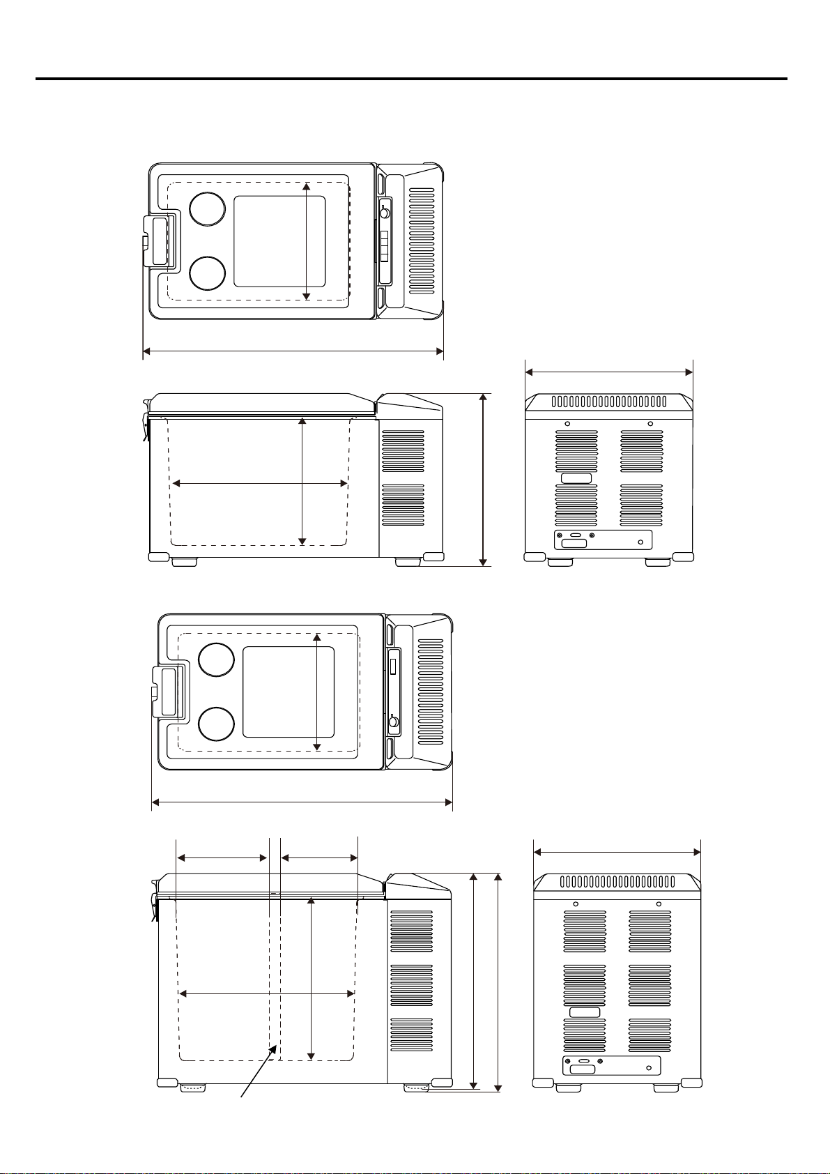
■ Exterior / Interior Dimensions
※ Tolerance is omitted
Unit (mm)
・MT35F
・MT45F
1. SPECIFICATIONS
2
298
408
648
364
390
275
648
364
508
398
390
275
DIVIDER (Combi type only)
215 160
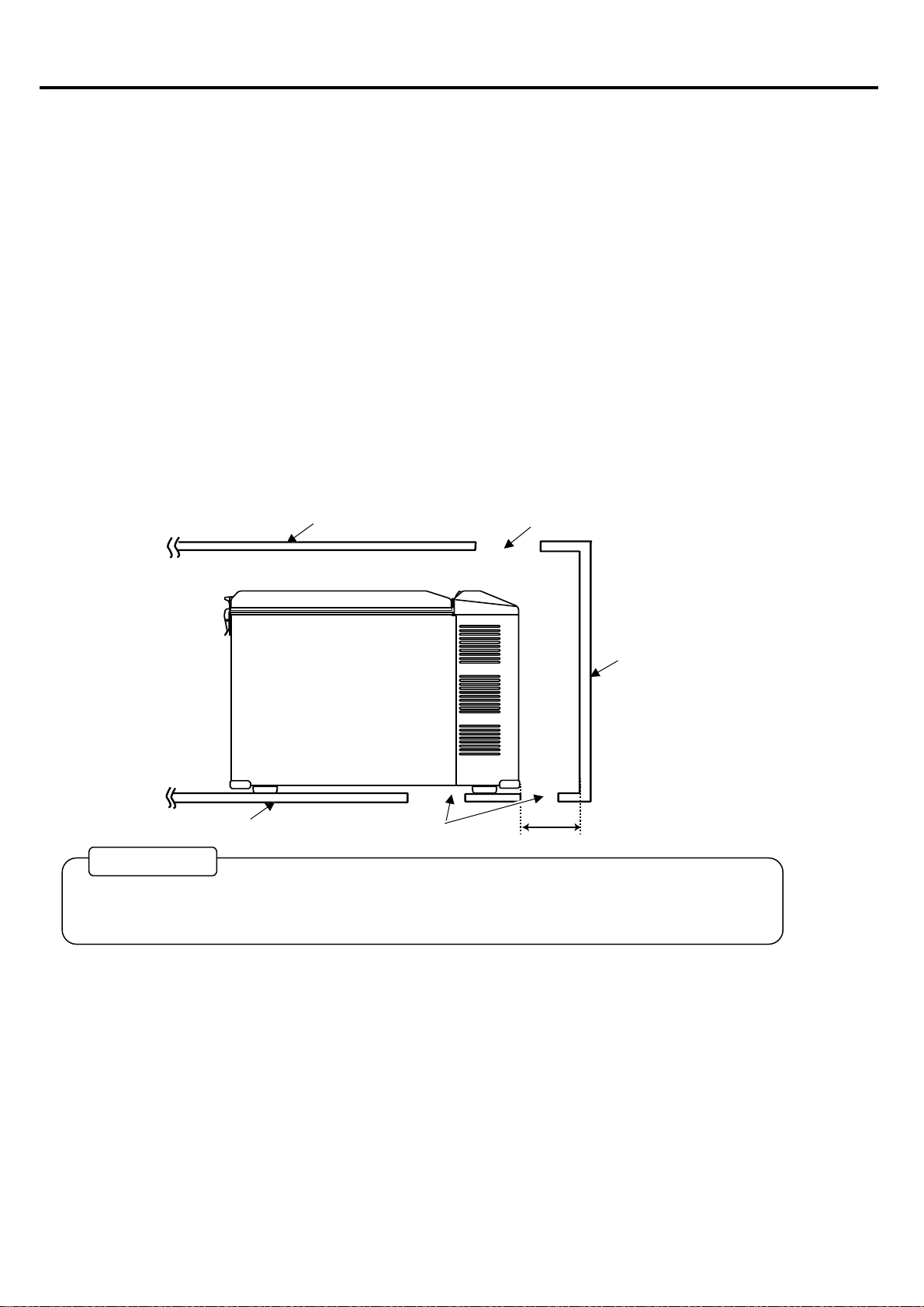
■ How to Install the Refrigerator.
(1) Your shockproof fridge is best installed on a solid surface.
(2) Be sure your fridge is not placed near a gas stove, heater or other
heat-generating appliances.
(3) Adequate ventilation and suitable distance from each wall (at least 150mm or more)
is necessary for the maximum cooling efficiency and minimum electric current consumption for
"free standing use"( see Fig.1 shown below).
(4) Avoid installing your fridge close to kitchen sink or faucet.
(5) If you use the fridge under the counter or in the fixing box, please note the
following air ventilation conditions.
① Make vent opening both under fridge or bottom and above fridge top cover.
2. INSTALLATION A REFRIGERATOR
3
② Vent opening size must be larger than 160㎠ for each opening ( the more air circulation over the
condenser, the more efficiently fridge will operate).
Failure to provide the necessary venting will result in poor refrigeration, continuous compressor
operation, accelerated battery discharge and sometimes shorten the life of fridge.
Top Cover Minimum Opening
Wall or Box Case
At least 150mm
From Each Wall
Floor or Box Bottom Minimum Opening
WORK TIPS
(Fig 1)
INDICATING
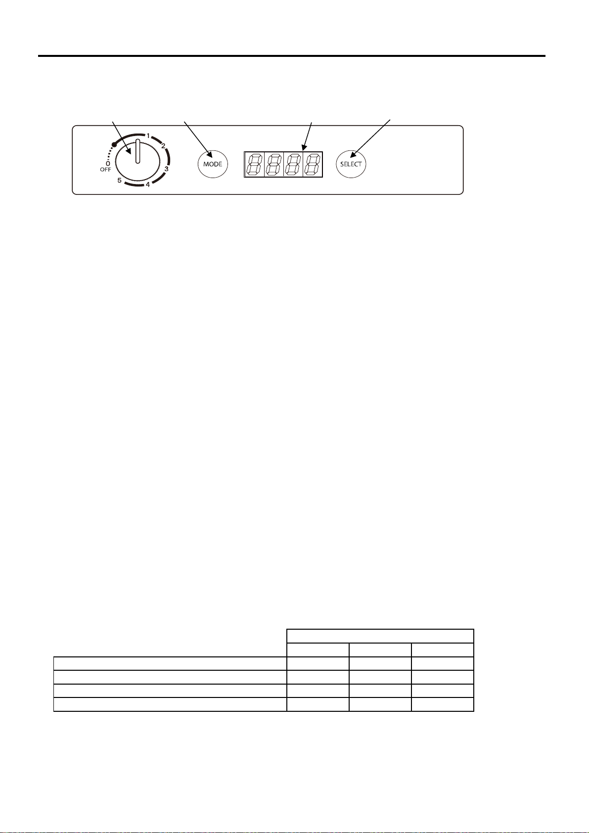
■ About digital displays
Displays the temperature inside the refrigerator, temperature setting display, error code, etc.
【How to set the temperature in the refrigerator】
Refrigerator temperature setting range is -18 ℃ to + 10 ℃
① Turn the dial to set the temperature inside the refrigerator. (-18 ° C to + 10 ° C)
② After a few seconds after you stop the dial, the temperature display changes from blinking to lit,
and the setting is confirmed.
③ After that, the LED display will show the temperature inside the refrigerator.
【How to switch between Celsius (℃) and Fahrenheit (℉)】
① Press the "MODE" button. (LED display blinks)
② Press the select button while the LED display is blinking to switch between Celsius and Fahrenheit.
③ After the setting is completed, after a few seconds, the LED will change from flashing to lit and
display Celsius or Fahrenheit.
【How to set the battery protection function】
This refrigerator has protection function for battery protection.
Set the operation stop and return of the refrigerator by the input voltage. (See table below)
① Press the mode button twice. (The current setting of the protection function is lit.)
② Every time you press the select button, the LED blinks and switches from “OFF” →“LO” → “HI”.
③ After a few seconds, the LED changes from blinking to lit and the setting is finalized.
④After that, the LED display will show the temperature inside the refrigerator.
【Error message display】
When an error message is displayed, the refrigerator goes into "standby mode" and stops operating.
To reset the error, reset the power.
At DC12V input Operation automatic return voltage
9.6V or less
23.1V
25.0V
An error message will be displayed on the LED display when the battery voltage is low or the refrigerator is
abnormal. (See page 8 for details)
4
10.5V
11.5V
9.6V or less
11.5V
12.5V
7.9V or less
21.0V
23.1V
* Operates when the voltage value continues for 10
seconds
At DC12V input Operation stop voltage
At DC24V input Operation stop voltage
At DC24V input Operation automatic return voltage
2. INSTALLATION A REFRIGERATOR
Battery protection settings
OFF
LO
HI
7.9V or less
LED display
"MODE"button "SELECT"button
DIAL
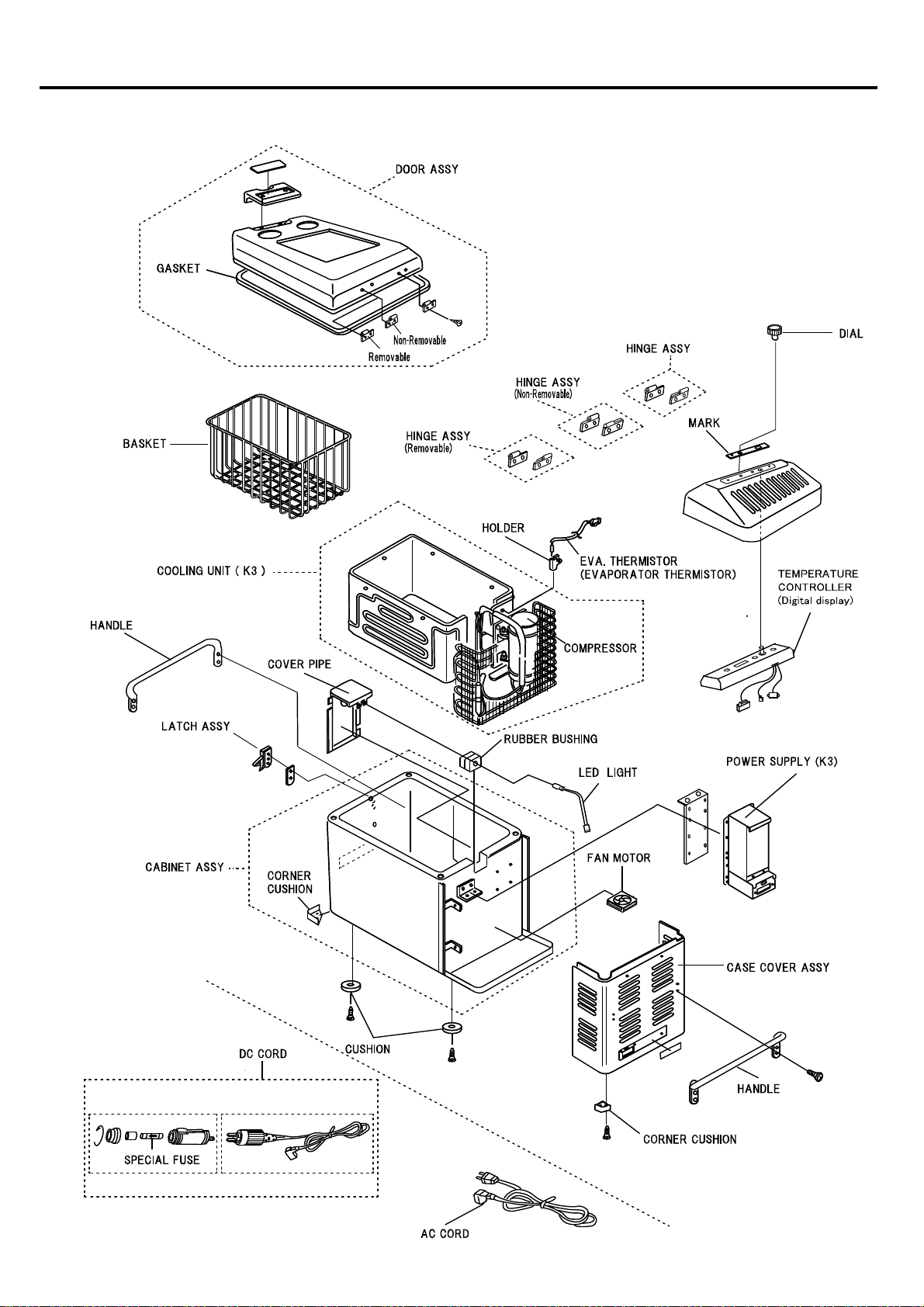
■ MT35F / MT45F (Non Combi type)
3. PART NAME
5
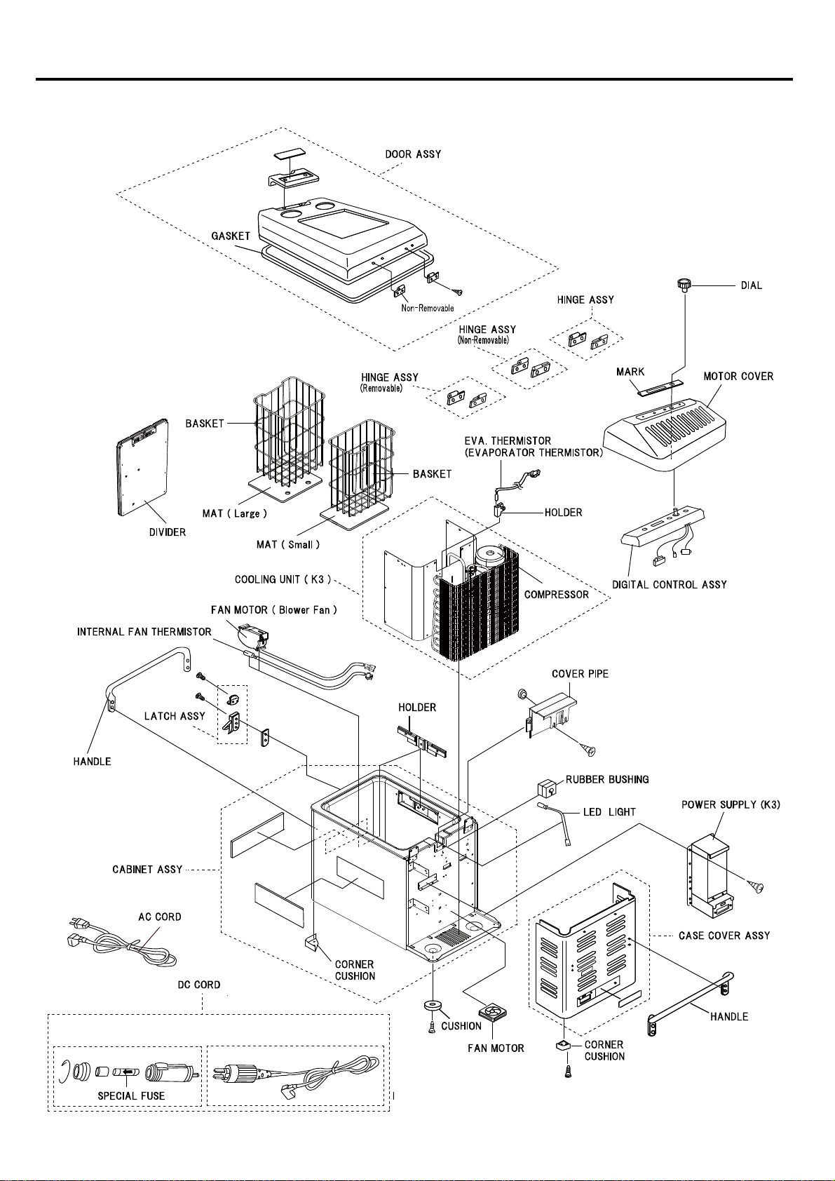
■ MT45F (Combi type)
3. PART NAME
6

■ MT35F / MT45F (Non Combi type)
● Block Diagrams
● Wiring Diagrams
7
4. CONNECTING DIAGRAM

■ MT45F (Combi type)
● Block Diagrams
● Wiring Diagrams
4. CONNECTING DIAGRAM
8
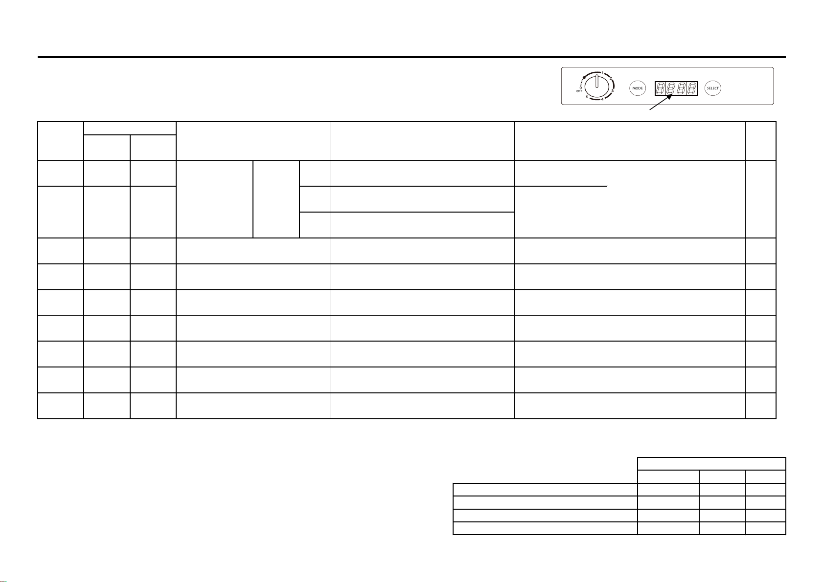
■ Error Message (Digital display of temperature controller)
Error message will be displayed if the voltage of the battery is low or in the event of any troubles - (see table below).
To reset the error, reset the power
Error message
※1 The voltage detection position is the terminal block of the refrigerator. (The voltages at the battery and terminal block are different to include the wiring drop.)
※2 No error is displayed if the fan is disconnected during operation. An error will occur at startup when the refrigerator is disconnected while the refrigerator is off.
■ About the battery protection function
This refrigerator has a battery protection function for battery protection.
(The above error code <.>)
If the battery voltage is low, the refrigerator stops as shown in the table on the right.
The refrigerator automatically returns when the battery voltage returns to normal voltage.
(Refer to page 8 for setting method)
At DC12V input Operation automatic return voltage
At DC24V input Operation stop voltage
At DC24V input Operation automatic return voltage
5. TROUBLE SHOOTING
9
9.6V or less
23.1V
25.0V
Battery protection settings
At DC12V input Operation stop voltage
HI
7.9V or less
10.5V
11.5V
9.6V or less
11.5V
12.5V
7.9V or less
21.0V
23.1V
E-5
Internal thermistor inspection
-
○
-
32.0V≦voltage(※1)≦35.0V (10s continuous)
Voltage(※1)≧45.0V (10s continuous)
E-4
○
○
E-8
14
Voltage(※1)≦ 9.6V (10s continuous)
17.0V ≦ voltage(※ 1)≦ 20.4V (10s continuous)
Voltage(※1)≦ 10.6V (10s continuous)
17.0V ≦ voltage(※ 1)≦ 22.5V (10s continuous)
14
SEE
PAGE
no display
The dot <.>
Flashes
○
○
○
Return condition
Battery
Protection
9.6V or more
-
E-9
E-10
ERROR
CODE
Other than
combi type
Combi type
Error code existence
CAUSE
Judgment criteria
SOLUTIONS
E-6
Power reset
Power reset
Power reset
Power reset
Increase ambient temperature or
move to a warmer place.
EVA.Thermistor inspection
EVA.Thermistor inspection
Check battery
E-7
○
○
○
○
○
○
○
-
○
Ambient temperature is too low
(Substrate ambient temperature)
Thermistor short or Internal temperature
overheating abnormality
Thermistor disconnection or internal
temperature drop abnormal
Abnormal input DC voltage (too
high)
Internal thermistor short or internal
temperature overheating
Internal thermistor disconnection or
internal temperature drop abnormal
Internal fan motor disconnection
※2, FAN voltage ≦ 1V or less (5s continuous)
LO
Power reset
Power reset
Power reset
Internal thermistor inspection
OFF
Temperature ≦ -40 ℃ (5s continuous)
○
Abnormal input
DC voltage
Voltage(※1)≦ 7.9V (10s continuous)
Temperature ≧ 75 ℃ (5s continuous)
Temperature ≦ -40 ℃ (5s continuous)
Temperature ≧ 75 ℃ (5s continuous)
OFF
LO
HI
14
14
Inspection of internal fan motor
15
* Operates when the voltage value
continues for 10 seconds
Check battery
-
-
See the table below
(battery protection
settings)
Temperature ≦ -20 ℃ (5s continuous)
※1 Ambient temp 25℃
※2 Ambient temp 25℃~-16℃
5. TROUBLE SHOOTING
10
Is the output voltage from the power
supply to the compressor normal?
Approx. AC13V - 18V ※1
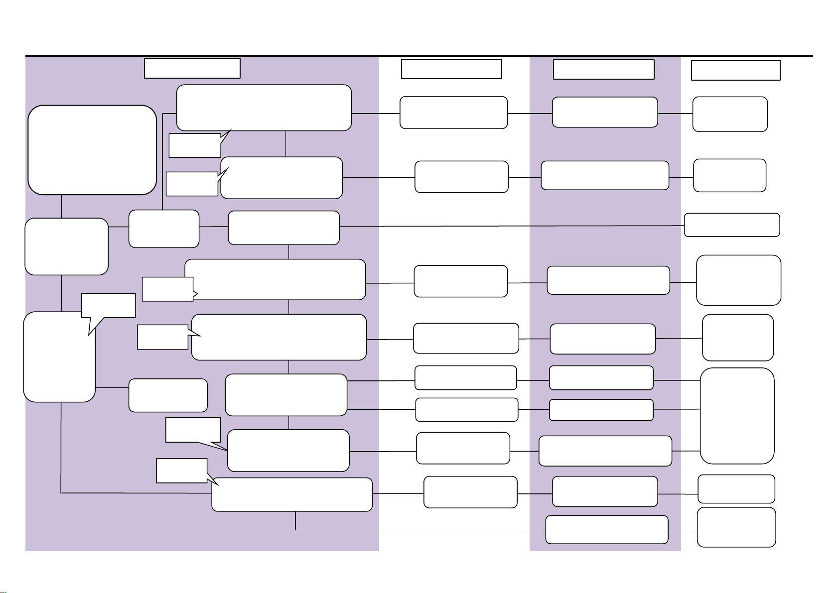
■Does not get Cold
(Temperature setting -18℃
)
Is compressor
running?
Lower than AC13V
Checking
Is the special
fuse of the DC
cord or the
blade fuse of
the power
supply blown?
Are wirings and couplers
connected?
Replace the
power supply.
Replace the fuse
See page 13
【Check 1】
See page 13
【Check 2】
Test result
Judge
Fixing
Connected repair.
Replace the
power supply.
See page15
【Check 7】
Power supply is
broken
Normal
Yes
Yes No
Normal
Normal
No
Yes
No
Out of standard Gas leak, clogging, etc.
Measurement of rated
current of refrigerator or
compressor
Replace the
cooling unit.
See page 15
【Check 7】
Is temperature
controller (digital
display) lit
?
Is the output voltage from the control
assembly to the power supply normal?
Normal
Abnormal
See page 14
【Check 5】
teperature controller
is broken.
Replace the
teperature
controller.
Replace the
power supply.
Lower than AC13V Power supply is
broken
Is the output voltage from the power
supply to the compressor normal?
Approx. AC13V - 18V ※1
See page 13
【Check 2】
Abnormal
Out of standard
Abnormal
Abnormal
Replace the
cooling unit.
Compressor lock etc.
Measurement of rated
current of refrigerator or
compressor
Compressor resistance
About 1.7Ω (at 25 ℃)
※Using analog tester
0Ω
∞Ω
Out of standard
Normal
Coil disconnection
Coil short circuit
Is the output voltage from the power
supply to the control assembly normal?
Out of standard Power supply is
broken
teperature controller
is broken.
Normal Replace the
teperature
controller.
See page 14
【Check 6】
Abnormal
Abnormal
Abnormal

※1 Ambient temp 25℃
※2 Ambient temp 25℃~-16℃
5. TROUBLE SHOOTING
11
■Cooling is Weak
Checking
Test result
Judge
Fixing
Battery voltage is lower than 11V
Voltage is too low.Voltage of battery 12V?
Charge the bettery
Is the machine part ventilated enough?
Make at least 150mm
room between unit and
wall.
YES
NO
Normal
Please keep the ambient
temperature below 30℃.
Ambient temperature is
too high.
Ambient temparature is higher than 30℃
NO
YES
There are too many things in the refrigerator.
Make some room for
cool air.
YES
Lower than AC13V
Replace the power supply.
Power supply is broken
Is the fan motor running?
NO
Fan motor is broken.
Replace the fan motor.
YES
The compressor is locked, or
contaminated.
Below reference value
Gas is leaking.
Replace the
cooling system.
NO
Normal
Insufficient ventilation.
Cool air does not spread.
See page 15
【Check 8】
Power supply &
Temperature
controller is
broken.
Replace the
power
supply &
Temperature
controller .
Resistance of the thermistor.
(Power supply, temperature controller side)
Approx. 2kΩ-10kΩ ※2
0Ω
Replace the
thermistor.
Normal
■Refrigerator is too cold.
(Can not be temperature adjustment)
See page 14
【Check 4】
Thermistor is
shorted.
NO
Power supply is broken
Replace the power supply.
Power is not coming to the
fan motor
Power is coming but fan
motor does not work
Above reference value
Measurement of rated
current of refrigerator or
compressor
See page 15
【Check 7】
Is the output voltage from the power
supply to the compressor normal?
Approx. AC13V - 18V ※1
See page 13
【Check 2】
Abnormal
■ Technical Data ※1 Ambient temp 25℃
※2 Ambient temp 25 to -16℃
Checking Points Normal data See page
Use DC12V → DC12V
Use DC24V → DC24V
Use AC100V → DC40V
Use DC12V → DC12V
Use DC24V → DC24V
Use AC100V → DC40V
See page 15 【Check 7】
See page 13 【Check 1】
Resistance of thermistor
Between two pin of the coupler
Approx. 2KΩ - 10KΩ ※2
Rated current of compressor
Measure the motor input code with a clamp meter.
See page 15 【Check 8】
See page 14 【Check 6】
See page 14 【Check 5】
Approx. 1.7Ω(K3) ※1
See page 13 【Check 3】
See page 14 【Check 4】
Approx. AC 13V - 18V ※1
Special fuse
Special fuse of DC cord
0Ω
Resistance of the compressor
Between incoming cords to compressor
(by detaching from terminal of compressor)
Output voltage from power supply to fan motor
Red (+) terminal and black (-) terminal of 2P fan power
coupler
DC18V
2.1A-2.3A ※1
5. TROUBLE SHOOTING
See page 13 【Check 2】
Checking items
12
Output voltage from power supply to
temperature controller
Output voltage from temperature controller to
power supply
Red (+) terminal and black (-) terminal of 6P coupler
terminal
6P coupler terminal orange (+) terminal and black (-)
terminal
Output voltage from power supply to
compressor
Between outgoing cords from power supply
(by ditaching from terminal of compressor)

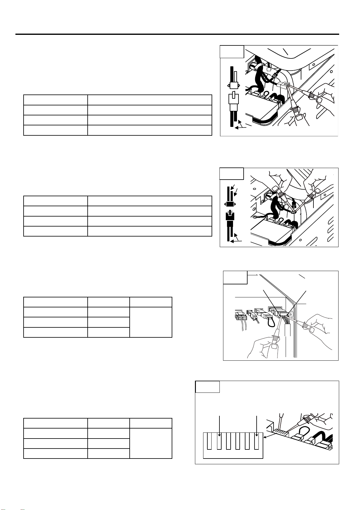
【Check 1】 Special Fuse & Blade Fuse. (Fig.1)
◇ Check the resistance of special fuse by tester.
Test result Judge
0Ω Normal
∞Ω Broken
◇ Check the blade fuse.
The blade fuse is in the power supply.
To remove the blade fuse, please remove the power supply.
【Check 2】 AC output voltage from power supply to compressor. (Fig.2)
◇ Checking point
Check at two pin coupler of power supply. (Fig.2)
Test result Judge
Approx. AC14 - 18V Normal
AC 0 V
Approx. AC14V or lower
【Check 3】 Check the Resistance at the Coil if Compressor.(Fig.3)
◇ Checking points
Remove two pin coupler at motor cord, and check.
(at25℃)
Test result Judge
Approx. 1.7 Ω Normal
∞Ω Disconnection of compressor coil
0Ω Coil of compressor is short circuit
Power Supply is broken
6. CHECK POINT &CHECK METHOD
13
・Please attach attention to the special fuse of
orientation.
・It can not detect the temperature is in the wrong
special fuse orientation. (※)
Fig.2
POWER SUPPLY
Fig.3
POWER SUPPLY
WORK TIPS
Fig.1
DC CORD
SPECIAL FUSE
BLADE FUSE (10A)
6. CHECK POINT &CHECK METHOD
【Check 4】 Resistance of Thermistor. (Fig.4)
<EVA.Thermistor resistance measurement>
(at25℃ ~ -16℃)
Test result
2 kΩ - 10 kΩ ※1
0Ω
∞Ω
※1 The resistance increases when the thermistor body is cold.
<Internal thermistor resistance measurement> (Combi type only)
(at25℃ ~ -16℃)
Test result
2 kΩ - 10 kΩ ※1
0Ω
∞Ω
※1 The resistance increases when the thermistor body is cold.
【Check 5】 Output DC voltage measurement from control assembly to power supply
Power supply used Test result Judge
DC12V DC11-14V
DC24V DC23-26V
AC100V
DC39-41V
【Check 6】 Output DC voltage measurement from power supply to control assembly
Power supply used Test result Judge
DC12V DC11-14V
DC24V DC23-26V
AC100V
DC39-41V
Thermistor disconnection (error display E-09)
14
Normal
Remove the power supply 6P coupler and
measure the DC voltage between the black (-)
wiring section and the red (+) wiring section on
the power supply side 6P coupler section (Fig.
7)
Normal
Remove the EVA / thermistor coupler (white) and measure the
resistance between the terminals. (Fig4)
Thermistor short (Error display E-05)
Normal
Judge
Thermistor disconnection (error display E-06)
DC voltage is measured between the black (-) terminal and
the orange (+) terminal of the power supply 6P coupler (Fig.
6)
Remove the coupler (black) of the internal fan thermistor
and measure the resistance between the terminals. (Fig5)
Judge
Normal
Thermistor short (Error display E-08)
Fig.5
Fig.4
Fig.6
Orange(+)Black(-)
Black
(-)
Red
(+)
Fig.7
Black
Black
Black
Black
Blue

【Check 7】 Compressor Rated Current. (Fig.8)
◇Checking point
Test result Judge
2.1 - 2.3A Normal
Lower than 2.1A Gas is leaking. ※
【Check 8】 Resistance of Fan motor.
<Compressor-side fan motor>
Check DC voltage from power supply to fan motor
Test result Judge
DC18V Normal
0V Power supply failure
When directly checking the operation of the fan motor
<Inside fan motor> (combi type only)
DC voltage confirmation from the control ASSY to the internal fan motor
Test result Judge
DC12V Normal
0V Control ASSY failure
When directly checking the operation of the fan motor
6. CHECK POINT &CHECK METHOD
15
Current value measurement with clamp meter between
input cord terminals.
Higher than 2.3A
Compressor is locked, or
contaminated. ※
※If the refrigerator does not cool down, or if the coldness is weak
◇Remove the fan motor coupler (white) on the compressor
side and measure the DC voltage between the coupler
terminals on the power supply side (Fig. 9)
◇You can check by directly connecting 18V to 24V DC, but
follow the precautions (Fig. 10)
◇Remove the internal fan motor coupler (black) and measure the DC
voltage between the control ASSY side coupler terminals (Fig. 11)
◇You can check by directly connecting 12V DC, but follow
the precautions (Fig. 12)
・Prepare a support coupler and perform measurement.
・Be careful not to mistake the polarity.
To measure the rated current of the compressor, please measure after 15 minutes or more after starting the
WORK TIPS
Fig.8
Fig.10
Fig.9
Support coupler
Fig.12
Black(-)
Red(+)
Black(-)
Red(+)
Red(+)
Black(-)
Red(+)
Black(-)
Fig.11
Support
coupler
Support
coupler
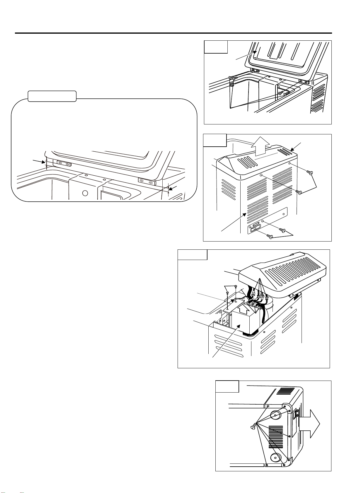
【How to Replace Cooling Unit】
1. Remove the door.
・Open the door and take out the basket.
・Remove the Divider. (Combi type only)
・Remove four screws which hold hinges. (Fig.1-①)
2. Remove the motor cover.
・Remove two screws of motor cover. (Fig.2-①)
・Remove two screws of case cover assy. (Fig.2-②)
・Remove the motor cover from the main unit. (Fig. 2-③)
3. Take out the power supply.
・Cut the fastener. (Fig.3-①)
・Remove two screws of power supply. (Fig.3-②)
・Take out the power supply. (Fig.3-④)
4. Remove the case cover assy.
Remove seven screws of case cover assy. (Fig.4-①)
Remove case cover assy. (Fig.4-②)
7. REPLACING PARTS
16
・Lift the power supply and remove the three
couplers. (Fig. 3-③)
・Remove all couplers of temperature control
assembly. (Fig. 3-⑤) (4 couplers for combi type,
3 couplers for non-combi type)
・Remove the temperature control assembly from
the main unit.
Fig.2
②
①
①
③
DOOR
Fig.1
14mm
14mm
WORK TIPS
When re-installing for door and hinges, please be care with placing position
of hinge height. Position must be 14mm from the cabinet.
(Please see reference picture in below)
After installation of door, please make sure for interior light not leak from
side of door.
If it's possible to see the light, please adjust height of hinges. MOTOR COVER
CASE COVER ASSY
Fig.3
④
⑤
①
POWER SUPPLY
GROUND CORD
②
③
Fig.4
①②

5. Remove screws of evaporator.
<For non combi type>
・Remove the 3 screws (Fig. 5-①)
<For combi type>
・Remove the 4 screws (Fig. 6-①)
6. Remove the cover pipe.
<For non combi type>
・Remove two screws of cover pipe. (Fig.7-①)
・Remove two fasteners of cover pipe. (Fig.7-②)
・Remove the cover pipe. (Fig.7-③)
・Remove the rubber bushing. (Fig.7-④)
・Remove LED light. (Fig.7-⑤)
<For combi type>
・Remove two screws of cover pipe. (Fig.8-①)
・Remove the cover pipe. (Fig.8-②)
・Remove the rubber bushing. (Fig.8-③)
・Remove LED light. (Fig.8-④)
7. REPLACING PARTS
17
Fig.5
①
EVAPORATOR
③
Fig.7
②
④
①
COVER PIPE
FASTENER
RUBBER
BUSHING
⑤
LED LIGHT
Fig.6
①
EVAPORATOR
①
①
Fig.8
①
④③
②COVER PIPE
LED LIGHT RUBBER
BUSHING
Other manuals for MT35F-U1D-P
1
This manual suits for next models
5
Table of contents
Other Engel Refrigerator manuals


Engel
Engel MT17F-G3 User manual

Engel
Engel MT15E User manual

Engel
Engel Eclipse MR40F-G4 User manual

Engel
Engel F Series User manual

Engel
Engel MT35F-G4ND-V User manual

Engel
Engel MT35F-U1D-P User manual

Engel
Engel MHD13F-DM User manual

Engel
Engel MR040F-U1 User manual

Engel
Engel MRBD030 User manual

Engel
Engel SB47F-E-T User manual


