Engel MD14F User manual

2020.12
#1
MODEL :
MD14F 0642 013 3000
SERVICE MANUAL

●FOR REFRIGERATOR USERS
・
Failing to service properly may result in poor reliability of the refrigerator.
・
Read this booklet carefully and perform servicing with great care.
・
●FOR SAFETY OF YOURSELF
・
●SAFETY SYMBOLS
・
The following warning labels in this booklet indicate precautions for service work.
Comply with what each symbol indicates whenever it appears.
●REFRIGERATOR MODEL
・
This manual is compatible with described model in below.
Please check refrigerator model.
(Lable place as picture)
MODEL
MD14F
To secure safe and correct servicing, read this manual thoroughly in advance and check if there
are protective equipment and appropriate tools and service parts ready as well as technical skills
necessary to perform servicing.
May lead to death or serious injury if failed to comply with this precaution
May lead to injury if failed to comply with this precaution
Lead to failure of the refrigerator set or its components if failed to comply
with this precaution
This service manual describes maintenance procedures for ENGEL refrigerator.
This manual is intended for repair engineers who are familiar with basics service skills and
knowledge for ENGEL refrigerator.
This manual does not guarantee correct maintenance when service is done by a non-skilled
worker without technical knowledge.
Note that the content of this booklet including product specifications is subject to change for
improvement without notice.
Always comply with the procedures, directions, and work tips in this booklet when servicing the
refrigerator.
WORK TIPS

CONTENTS
1. SPECIFICATIONS ・・・・・・・・・・・・・・・・・・・・・・・・・・・・・・・・・・・・・・・・・・・・・・・・・・・・・・・・・・・・・・・・・・・・・・
1
■ Specifications Table ・・・・・・・・・・・・・・・・・・・・・・・・・・・・・・・・・・・・・・・・・・・・・・・・・・・・・・
1
■ Dimensions ・・・・・・・・・・・・・・・・・・・・・・・・・・・・・・・・・・・・・・・・・・・・・・・・・・・・・
2
2. INSTALLING A REFRIGERATOR ・・・・・・・・・・・・・・・・・・・・・・・・・・・・・・・・・・・・・・・・・・・・・・・・・・・・・・・・・・・・・・・・・・・・・・・・・・・
3
■ Installation ・・・・・・・・・・・・・・・・・・・・・・・・・・・・・・・・・・・・・・・・・・・・・・・・・・ 3
■ Temperature Setting ・・・・・・・・・・・・・・・・・・・・・・・・・・・・・・・・・・・・・・・・・・・・・・・・・・
3
3. PARTS NAME ・・・・・・・・・・・・・・・・・・・・・・・・・・・・・・・・・・・・・・・・・・・・・・・
4
4. CONNECTING DIAGRAM ・・・・・・・・・・・・・・・・・・・・・・・・・・・・・・・・・・・・・・・・・・・・・・・
5
■ Block Diagrams ・・・・・・・・・・・・・・・・・・・・・・・・・・・・・・・・・・・・・・・・・・・・・・・・・・・・・・・・・・・・・・・・・・・・・
5
■ Wiring Diagrams ・・・・・・・・・・・・・・・・・・・・・・・・・・・・・・・・・・・・・・・・・・・・・・・・・・・・・・・・・・・・
5
5. TROUBLE SHOOTING ・・・・・・・・・・・・・・・・・・・・・・・・・・・・・・・・・・・・・・・・・・・・・・・・・・・・・・・・・・・・・・・・・・・・・・・・・・・
6
■ Does not get Cold ・・・・・・・・・・・・・・・・・・・・・・・・・・・・・・・・・・・・・・・・・・・・・・・・・・・・・・・・・・・・
6
■ Cooling is Weak ・・・・・・・・・・・・・・・・・・・・・・・・・・・・・・・・・・・・・・・・・・・・・・・・・・・・・・・・・・・・
7
■ Refrigerator is too Cold. (Can not be temperature adjustment) ・・・・・・・・・・・・・・・・・・・・・・・・・・・・・・・・・・・・・・・・・・・・・・・・・・・・・・・・・・・・
8
■ Typical Problem ・・・・・・・・・・・・・・・・・・・・・・・・・・・・・・・・・・・・・・・・・・・・・・・・・・・・・・・・・・・
9
■ Technical Data ・・・・・・・・・・・・・・・・・・・・・・・・・・・・・・・・・・・・・・・・・・・・・・・・・・・
9
6. CHECK POINT&CHECK METHOD ・・・・・・・・・・・・・・・・・・・・・・・・・・・・・・・・・・・・・・・・・・・・・・・・・・・・・・・・・・・・・・・・・・
10
【Check 1】 Special Fuse. ・・・・・・・・・・・・・・・・・・・・・・・・・・・・・・・・・・・・・・・・・・・・・・・・・・
10
【Check 2】 Output Voltage of the Power Supply. ・・・・・・・・・・・・・・・・・・・・・・・・・・・・・・・・・・・・・・・・・・・・・・・・・
10
【Check 3】 Input Voltage of the Compressor. ・・・・・・・・・・・・・・・・・・・・・・・・・・・・・・・・・・・・・・・・・・・・・・・・・
10
【Check 4】 Resistance of the Compressor. ・・・・・・・・・・・・・・・・・・・・・・・・・・・・・・・・
11
【Check 5】 Resistance of the EVA. Thermistor. ・・・・・・・・・・・・・・・・・・・・・・・・・・・・・・・・・・・
11
【Check 6】 Resistance of the Registor Variable. ・・・・・・・・・・・・・・・・・・・・・・・・・・・・・・・・・・・・・・・・・・・・・・・・・・・・・・・・・・
11
【Check 7】 Fan Motor Assy. ・・・・・・・・・・・・・・・・・・・・・・・・・・・・・・・・・・・・・・・・・・・・・・・・・・・・・・・・・・
12
【Check 8】 Compressor Rated Current. ・・・・・・・・・・・・・・・・・・・・・・・・・・・・・・・・・・・・・・・・・・・・・・・・・・・・・・・・・・
12
7. REPLACING PARTS ・・・・・・・・・・・・・・・・・・・・・・・・・・・・・・・・・・・・・・・・・・・・・・・・・・・・・・・・・・・・・・・・・・・・・・
13
【How to Replace Cooling System】 ・・・・・・・・・・・・・・・・・・・・・・・・・・・・・・・・・・・・・・・・・・・・・・・
13
【How to Replace Power Supply】 ・・・・・・・・・・・・・・・・・・・・・・・・・・・・・・・・・・・・・・・・・・・・・・・・・・・・・・・・・・・
14
【How to Replace Fan Motor】 ・・・・・・・・・・・・・・・・・・・・・・・・・・・・・・・・・・・・・・・・・・・・・・・・・・・・・・・・・・・
14
【How to Replace Registor Variable】 ・・・・・・・・・・・・・・・・・・・・・・・・・・・・・・・・・・・・・・・・・・・・・・・・・・・・・・・・・・・
15
■ Specifications Table
STORAGE VOLUME L
in
mm
in
mm
Material
Heat
insulator
Material
Heat
insulator
INPUT VOLTAGE V
RATED AMPERAGE A
LBS.
Kg
※ Tolerance is omitted
1. SPECIFICATIONS
MODEL
14
442×284×398 ※
348×190×213 ※
DOOR
WEIGHT
25.3
11.5
CABINET
Polypropylene resin
17.4×11.2×15.7 ※
INTERIOR
DIMENSIONS
W×D×H
13.7×7.5×8.4 ※
DC 12V
TEMPERATURE CONTROL
Automatic temperature control by dial setting
(Electronic thermostat control type)
Polypropylene resin
MODEL CODE
Foamed polyurethane
EXTERIOR
DIMENSIONS
W×D×H
AC 15V, 27W
MD14F
0642 013 3000
Foamed polyurethane
DC 2.8A
(Input voltage DC 12.8 V, Ambient temperature 30℃)
COMPRESSOR RATING
1
REFRIGERANT
Dichlorodifluoromethane (HFC-134a)
TEMPERATURE CONTROL
NOTCH 5 OR FREEZE
Less than −18 ℃
(Ambient temperature 30℃)

■ Dimensions
※ Tolerance is omitted
(mm)
1. SPECIFICATIONS
2
284
190
442
213
348
398
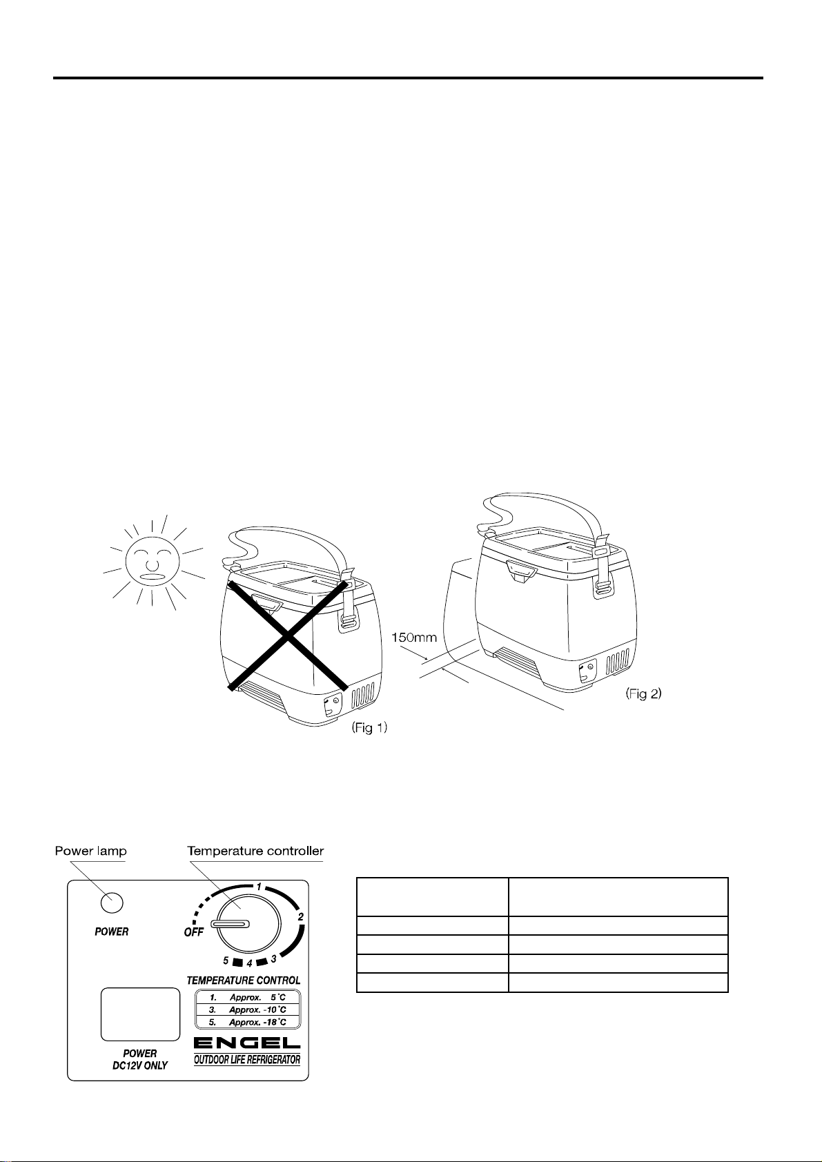
■ Installation
①
②
③
④Install refrigerator away from each wall at least 150mm or more. (Fig 2)
⑤Avoid installing your fridge close to a kitchen sink or faucet. (water)
⑥Clean the interior with a cloth moistened in warm water and wipe with a dry cloth.
⑦Never use the ENGEL refrigerator inside a freezer container car or refrigerator container car.
■ Temperature Setting
Set the cabinet inside air temperature range by means of the Temperature controller.
2. INSTALLING A REFRIGERATOR
3
Your shockproof fridge should be installed on a level and solid surface although it will operate
satisfactory for long period on angles of up to 30°.
Be sure your fridge is not in direct sunlight, (Fig 1) near a gas stove, heater, or other heat-
generating appliances.
In order to get good cooling performance and less current consumption, adequate ventilation
for refrigerator is needed.
Condensation can easily occur in the interior of the refrigerator container car and freezer
container car, causing water drops to fall in the refrigerator and damage the equipment.
Temperature controller
position
Cabinet inside air
Temperature range
OFF
Stop and defrosting
※At ambient temperature 30℃ under the refrigerator door
in closed condition.
1
Approx.5℃(41°F)
3
Approx.-10℃(14°F)
5
Approx.-18℃(5°F)
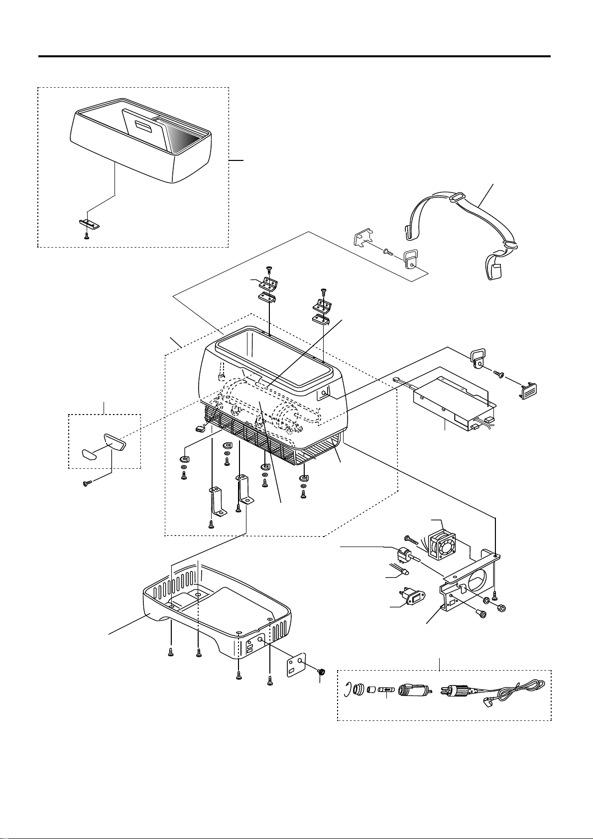
3. PARTS NAME
4
SHOULDER STRAP
REGISTOR VARIABLE
(TEMPERATURE CONTROLLER)
FAN MOTOR
POWER SUPPLY
COOLING SYSTEM
LATCH ASSY
DIAL
DOOR ASSY
CASE BOTTOM
POWER LAMP
TERMINAL BLOCK
DC CORD
HINGE
SPECIAL FUSE
HOLDER ASSY
COMPRESSOR
EVAPOLATOR
THERMISTOR (EVA. THERMISTOR)
(It is inside the insulation)
WIRE
CONDENSER

■ Block Diagrams
■ Wiring Diagrams
4. CONNECTING DIAGRAM
5

Normal
Yes
No
No
Yes
Yes
No No
Yes
No
※1 Ambient temp 25℃
※2 Ambient temp 25℃ to -16℃ ※4 Replacement of only the thermistor can not.
※3 Use tester: Digital multimeter It will be the exchange of the cooling system.
5. TROUBLE SHOOTING
6
Yes
■Does not get cold.
Checking
Is fuse blown?
Are wirings and couplers
connected?
Power check on the
vehicle side
Replace the fuse
See page 10
【Check 1】
Test result
Judge
Fixing
Connected repair.
Resistance of the compressor.
Approx. 1.6Ω ※1, ※3
Compressor coil is
disconnection.
Replace the
cooling system.
0Ω
Compressor coil is
shorted.
∞Ω
Resistance of the thermistor.
Approx. 2kΩ -10kΩ※2
Thermistor is broken.
∞Ω
Power supply output voltage.
Approx. AC11V - 18V ※1
AC 0V
Power supply is
broken.
Replace the
power supply.
Lower than AC11VOutput
maladjustment.
See page 11
【Check 5】
Normal
Normal
Normal
Power supply output voltage.
Approx. AC11V - 18V ※1
Lower than AC11V
Replace the
power supply.
Output
maladjustment
See page 11
【Check 4】
See page 10
【Check 2】
DC
cord
lamp
lit?
Power lamp lit?
Is compressor
running?
Check the fridge, Go to C
(Next page)
Replace the
cooling system.
※4
The compressor is locked, or
contaminated.
Replace the
cooling system.
A
See page 10
【Check 2】
Higher than 2.0A
The compressor is locked, or
contaminated.
Lower than 1.7A Gas is leaking.
Compressor rated current.
Approx. 1.7A - 2.0A
Replace the
cooling system.
See page 12
【Check 8】

※1 Ambient temp 25℃
7
5. TROUBLE SHOOTING
■Cooling is weak
Checking
Test result
Judge
Fixing
Battery voltage is lower than 10V
Voltage is too low.Voltage of battery 10V - 13V?
Charge the bettery
Is the machine part ventilated enough?
Make at least 150mm
room between unit and
wall.
YES
NO
Normal
Please keep the ambient
temperature below 30℃.
Ambient temperature is
too high.
Ambient temparature is higher than 30℃
NO
YES
There are too many things in the refrigerator.
Make some room
for cool air.
YES
Power supply output voltage.
Approx. AC11V - 18V ※1
Lower than AC11V
Replace the power supply.
Output maladjustment
Is the fan motor running?
NO
Fan motor is broken.
Replace the fan motor.
YES
Higher than 2.0A
The compressor is locked, or
contaminated.
Lower than 1.7A Gas is leaking.
Compressor rated current.
Approx. 1.7A - 2.0A
Replace the
cooling system.
Replace the
registor
variable.
0Ω
Registor variable is
shorted.
∞Ω
Resistance at the registor variable.
Approx. 5kΩ-15kΩ
Dial position 5 - OFF
(Resistance value changes in the dial position.)
Registor variable is
broken.
NO
Normal
Normal
See page 11
【Check 5】
See page 11
【Check 6】
See page 12
【Check 8】
Insufficient ventilation.
Cool air does not spread.
See page 12
【Check 7】

Normal
Normal
Normal
※2 Ambient temp 25℃ to -16℃
※4 Replacement of only the thermistor can not.
It will be the exchange of the cooling system.
5. TROUBLE SHOOTING
8
■
Refrigerator is too cold.
(Can not be temperature adjustment)
Checking
Test result
Judge
Fixing
Resistance of the thermistor.
Approx. 2kΩ -10kΩ ※2
Thermistor is short.
0Ω
Replace the
registor
variable.
0Ω
Registor variable is
shorted.
∞Ω
Resistance at the registor variable
.
Approx. 5kΩ-15kΩ
Dial position 5 - OFF
(Resistance value changes in the dial position.)
Power supply is
broken.
Replace the
power supply.
Registor variable is
broken.
C
See page 11
【Check 5】
Replace the
cooling system.
※4
See page 11
【Check 6】

※1 Ambient temp 25℃
■ Typical Problem ※2 Ambient temp 25℃ to -16℃ ※4 Replacement of only the thermistor can not.
※3 Use tester: Digital multimeter It will be the exchange of the cooling system.
Symptoms Cause Test Result Treatment
Resistance of compressor is ∞Ω
・Normal: Approx. 1.6Ω ※1, ※3
Output voltage of power supply is AC 0V
・Normal: Approx. AC11-18V ※1
Resistance of EVA. thermistor ∞Ω
・Normal: Approx. 2kΩ-10kΩ ※2
Replace of cooling system
Replace fan motor
Charge the bettery
-
Make some room for cool air
Replace the fuse
Replace the fuse
Check the vehicle
■ Technical Data ※1 Ambient temp 25℃ ※3 Use tester: Digital multimeter
※2 Ambient temp 25℃ to -16℃
Checking Points Normal data
Approx. 15kΩ - 5kΩ
Dial position OFF - 5
0Ω
Resistance of EVA. thermistor
Between two pin of the coupler
Approx. 1.6Ω ※1, ※3
Fuse in the vehicle is open
Ventilation at mechanical part is not enough
Checking items
Output voltage of power supply
Input voltage at compressor
Too many things are put inside
Replace the cooling system
Replace the cooling system
※4
EVA. thermisitor is open
Coil of the compressor is open
Compressor does not
work
Power supply is broken
Inside of the fridge does
not get cold
9
Approx. AC 11V - 18V ※1
Between outgoing cords from power supply
Approx. AC 11V - 18V ※1
Socket or other DC power line in the vehicle is bad
Resistance of the compressor
Special Fuse
Fuse at power supply
Approx. 2KΩ - 10KΩ ※2
Between incoming cords to compressor
Power lamp is lit.
Gas is leaking from Cooling Unit
Fan motor is broken
Input voltage is lower than 10V
The special fuse inside DC cord is open
Ambient temparature is higher than 30℃
Cooling is weak
5. TROUBLE SHOOTING
Resistance of the registor variable
Between terminals brown and black.
Current value measurement with clamp meter
between input cord terminals.
Compressor rated current
Approx. 1.7A - 2.0A
Replace power supply
Make at least 150mm room
between unit and wall
Between terminals of compressor
Power lamp is not lit.
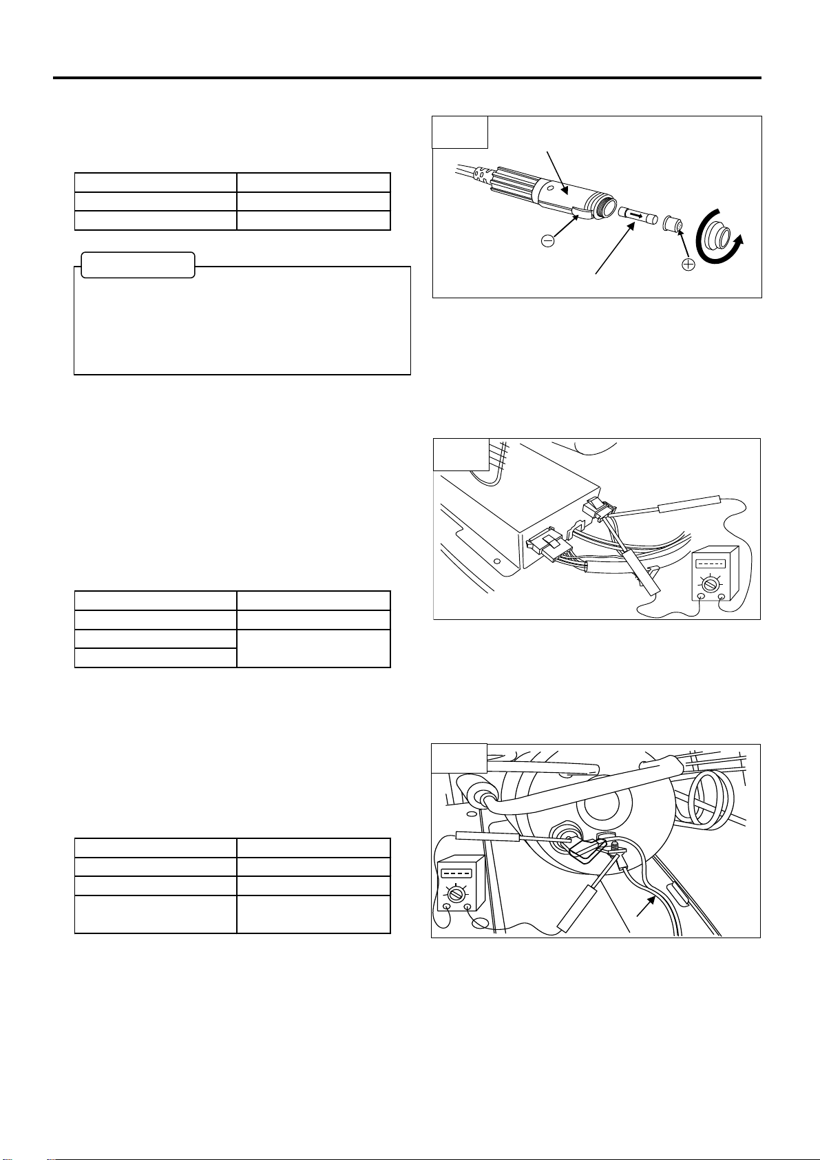
【Check 1】 Special Fuse. (Fig.1)
◇ Check the resistance of special fuse by tester.
Test result Judge
0Ω Normal
∞Ω Broken
【Check 2】 Output Voltage of the Power Supply. (Fig.2)
◇Checking point
・Check at two pin coupler of power supply
or at input terminals of the compressor.
(See 【Check 3】)
(Ambient temp 25℃)
Test result Judge
Approx. AC11V - 18V Normal
Lower than AC11V
AC 0 V
【Check 3】 Input Voltage of the Compressor. (Fig.3)
◇Checking point
Voltage measurement between terminals of input cord.
Test result Judge
Approx. AC11V - 18V Normal
Lower than AC11V Power Supply is broken
10
6. CHECK POINT&CHECK METHOD
AC 0 V
Power Supply is broken or
input cord disconnection
Power Supply is broken
Fig.1
SPECIAL FUSE
DC CORD
Fig.2
Fig.3
INPUT CORD
・Please attach attention to the special fuse of
orientation.
・It can not detect the temperature is in the wrong
special fuse orientation. (※)
WORK TIPS
※

【Check 4】 Resistance of the Compressor. (Fig.4)
◇Checking points
Remove two pin couplers at input cord, and check.
(Ambient temp 25℃)
Test result Judge
Approx. 1.6 Ω Normal
∞Ω Broken
※3 Use tester: Digital multimeter (HIOKI (DT4251))
【Check 5】 Resistance of the EVA. Thermistor. (Fig.4)
◇Checking points
Remove the two pin couplers from power supply, and
test.
(Ambient temp 25℃ to -16℃)
Test result Judge
Approx. 2 kΩ - 10 kΩ Normal
∞Ω Broken
0Ω Short Circuit
※ When short circuit, compressor runs continuously.
【Check 6】 Resistance of the Registor Variable. (Fig.6)
◇Checking point
Remove six pin coupler.
Check the resistance at between terminals
brown and black.
※Resistance value changes in the dial position.
0Ω
Judge
Normal
Broken
Short Circuit
11
∞Ω
0Ω
Coil of compressor is short
circuit
6. CHECK POINT&CHECK METHOD
Test result
Dial position OFF - 5
Approx. 15kΩ - 5kΩ
Fig.5
BROWN
BLACK
OFF
MAX 5
Fig.6
Replacement of only the EVA. thermistor can not.
It will be the exchange of the cooling system.
WORK TIPS
Fig.4
※3
INPUT CORD
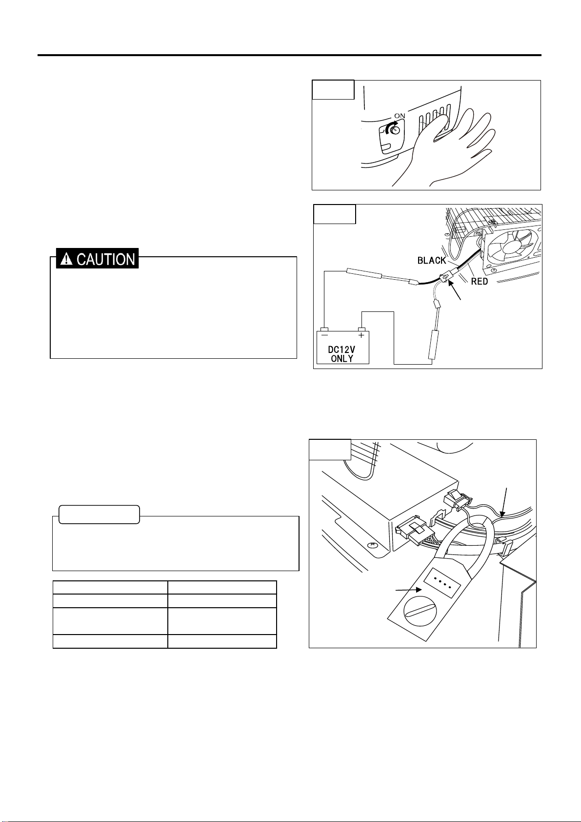
【Check 7】 Fan motor Assy. (Fig.7)
◇Checking point
If the refrigerator of the switch is ON, the fan motor will start.
Please make sure that the wind has come out by hand.(Fig.7)
If the wind does not come out (fan is not moving),
the failure of the fan motor or, will be the code breaking.
◇Checking point
If want to check the start-up of the fan motor directly,
can check by connecting the DC12V directly. (Fig.8)
【Check 8】 Compressor rated current (Fig.7)
◇Checking point
Test result Judge
Approx. 1.7 - 2.0A Normal
Lower than 1.7A Gas is leaking.
12
Compressor is locked, or
contaminated.
Higher than 2.0A
Current value measurement with clamp meter
between input cord terminals.
6. CHECK POINT&CHECK METHOD
・Please be careful not to mistake the polarity of the
power supply.
・When connect with DC24V or wrong polarity,
fan motor will fail.
・Please use such as support coupler so as not to
short-circuit power.
Fig.7
Fig.8
CLAMP METER
To measure the rated current of the compressor,
please measure after 10 minutes or more after
starting the refrigerator.
Fig.9
WORK TIPS
INPUT CORD
SUPPORT COUPLER
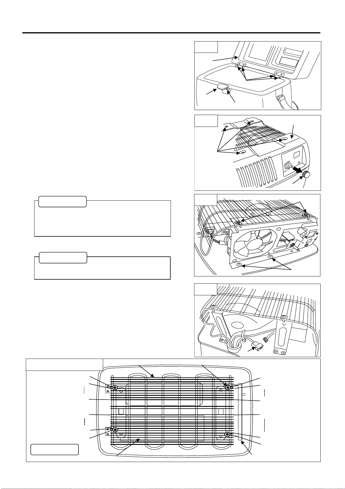
【How to Replace Cooling System】
1. Remove four screw (Fig.1-①), remove the door assy.
2. Remove screw (Fig.1-②), remove the latch
3. Pull out thermostat dial. (Fig2-①)
4. Remove four screw, remove the bottom case.(Fig.2-②)
5. Remove two screws that stop the wire condensor. (Fig3‐①)
6. Remove two screws, remove the holderassy. (Fig3-②)
7. Remove two pin coupler of EVA. thermistor. (Fig4-①)
7. REPLACING PARTS
13
LATCH
Fig.1
②
①
DOOR
ASSY
①
②
Fig.2
CASE BOTTOM
Fig.4
①
In the case of power supply only exchange,
WORK TIPS
Fig.3
①
②
During assembly, please tighten the screws in
the same position as the removed screw
position. (See below; "Screws position")
WORK TIPS
1st
9th
10th
7th
6th
1st
7th
6th
1st
1st
7th
8th
Screws position
POWER SUPPLY
HOLDER ASSY
WIRE CONDENSER
SCREW
WORK TIPS
8.
9.
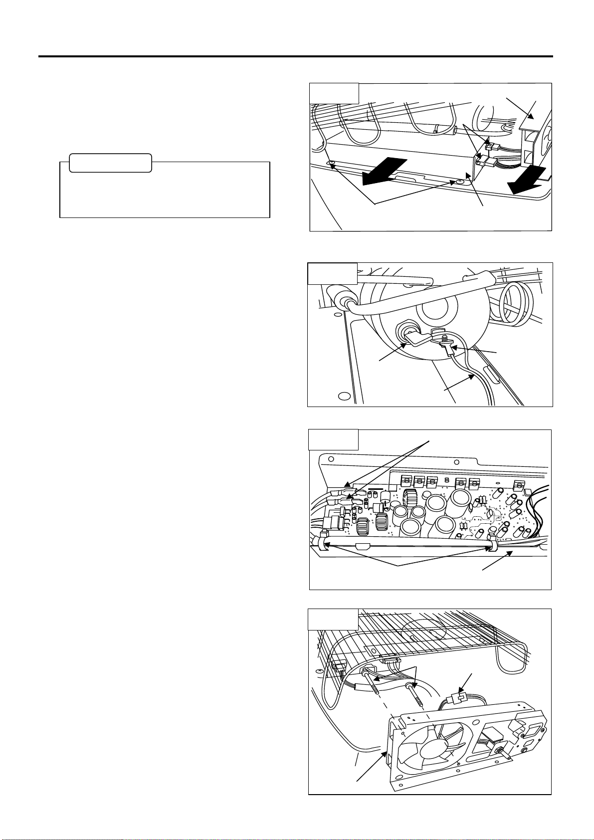
【How to Replace Power Supply】
1.
2. The fastener is cut by two places.(Fig.7-①)
3. Remove two flag terminals. (Fig.7-②)
【How to Replace Fan Motor】
1.
2. Remove two screws. (Fig.8‐①)
3. Remove the coupler. (Fig.8‐②)
7. REPLACING PARTS
14
Remove two screws (Fig.5-①) and remove the
two couplers.(Fig.5-②)
Pull out the power supply and holder assy from
the main body. (Fig.5-③)
Remove the input cord from the compressor.
(Fig.6-①、②)
Perform the procedure of how to replace the
cooling system. (Page 15 Step 3~9)
Perform the procedure of how to replace the
cooling system. (Page 15 Step 3~6)
Fig.5
②
Fig.6
①
②
②
Fig.7
②
POWER SUPPLY
Fig.8
①
③
①
POWER SUPPLY
③
HOLDER ASSY
INPUT CORD
In the case of power supply only exchange,
the holder assembly is not removed.
WORK TIPS
①
②
FAN MOTOR
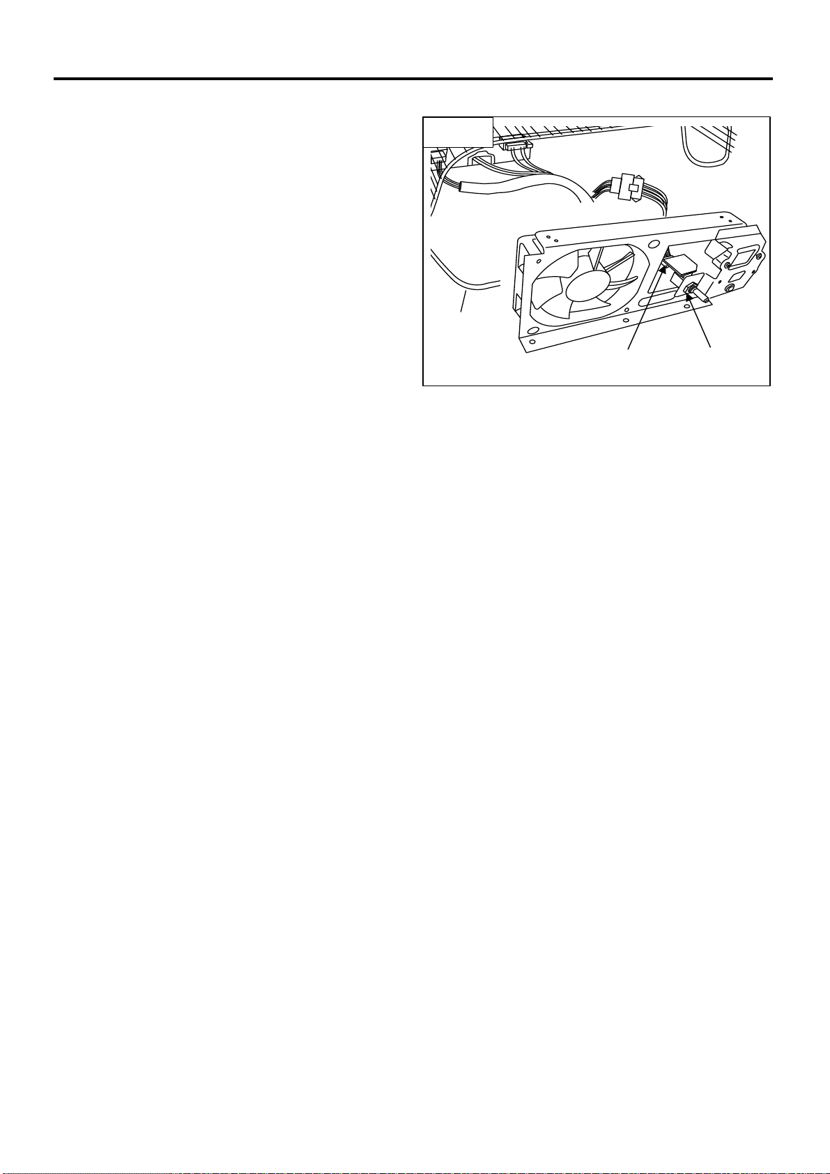
【How to Replace Registor Variable】
1. Perform the procedure of how to replace the
cooling system. (Page 15 Step 3~6)
2. Remove nut & washer. (Fig.9‐①)
3. Remove the coupler. (Fig.9‐②)
15
7. REPLACING PARTS
Fig.9
②
①

Other manuals for MD14F
2
This manual suits for next models
1
Table of contents
Other Engel Refrigerator manuals

Engel
Engel MT45F-S User manual

Engel
Engel SR48F User manual

Engel
Engel MHD13F-DM User manual

Engel
Engel SB47F-E-T User manual

Engel
Engel MT17F User manual

Engel
Engel MT35F-U1D-P User manual

Engel
Engel ST68E User manual

Engel
Engel MR040F-G3 User manual

Engel
Engel MT35F-G3ND-V User manual

Engel
Engel MT60F-U1 User manual

Engel
Engel MT35F-U1D-P User manual

Engel
Engel MR040F-U1 User manual

Engel
Engel SB30G User manual

Engel
Engel Eclipse MR40F-G4 User manual

Engel
Engel MD14E Manual

Engel
Engel MD14F User manual

Engel
Engel MRBD030 User manual

Engel
Engel SR48F User manual

Engel
Engel MT80F-G4-S User manual

Engel
Engel MHD13F-DM User manual


