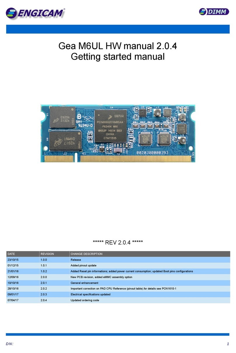
ENGICAM MicroGEA MX6ULL 512MB LCD Parts list manual

MicroGEA MX6 ULL HW manual 1.0.6
Getting started manual
***** REV 1.0.6 *****
ATE REVISION CHANGE ESCRIPTION
29/11/2017 1.0.0 Release
21/02/2018 1.0.1 Proofread & correct grammar & added connector code for the Carrier board's interface
05/04/2018 1.0.2 Added connector information, moved chapter 7 to the adapter application notes
17/07/2018 1.0.3 Added Resistive Touch information. Updated sleep mode current consumption
18/07/2018 1.0.4 Updated ordering Information table
17/09/2018 1.0.5 Added in-rush current requirements during start-up
24/10/2018 1.0.6 Updated ordering code, update mechanical information, updated LC and touch connections chapter
D N : 1

Table of Contents
1. Introduction.................................................................................................................................................. 3
1.1 Introduction............................................................................................................................................................... 4
1.2 Acronyms and Abbreviations used...........................................................................................................................4
1.3 ocument and Standard References.......................................................................................................................5
1.3.1 External Industry Standard ocuments...................................................................................................................................5
1.3.2 NXP ocuments.......................................................................................................................................................................5
2. Mechanical data........................................................................................................................................... 6
2.1 Mechanical data....................................................................................................................................................... 7
2.2 Assembly Top View................................................................................................................................................... 7
2.3 Assembly Bottom View.............................................................................................................................................7
2.4 Interface Connectors................................................................................................................................................ 8
3. Ordering Information and Features.............................................................................................................. 9
3.1 Ordering Information............................................................................................................................................... 10
4. Pinout......................................................................................................................................................... 12
4.1 Module Pinout......................................................................................................................................................... 13
4.2 Electrical specifications..........................................................................................................................................18
5. Carrier Board esign................................................................................................................................. 19
5.1 Carrier board recommended specifications............................................................................................................20
5.1.1 Planarity in finish process.......................................................................................................................................................20
5.1.2 Planarity of PCB......................................................................................................................................................................20
5.1.3 Power Supply..........................................................................................................................................................................20
5.1.4 Module Positioning and fixing................................................................................................................................................20
5.2 How to power the module.......................................................................................................................................21
5.2.1 How to connect a backup battery...........................................................................................................................................22
5.3 How to connect two 3-wire RS232 serial port.........................................................................................................23
5.4 How to connect a RS485 serial port....................................................................................................................... 24
5.5 How to connect CAN BUS interfaces.....................................................................................................................25
5.6 How to design the Ethernet interface.....................................................................................................................26
5.6.1 Component Placement considerations..................................................................................................................................28
5.6.2 Cable Transient Event and PHY Protection...........................................................................................................................29
5.6.3 Phy Ethernet...........................................................................................................................................................................30
5.7 USB interface......................................................................................................................................................... 31
5.7.1 How to connect the USB OTG interface................................................................................................................................31
5.7.2 How to connect the USB host interface.................................................................................................................................33
5.8 How to connect the S CAR interface.................................................................................................................34
5.9 How to connect an LC display.............................................................................................................................35
5.9.1 Connection map for 18 bit display..........................................................................................................................................35
5.9.2 Connection map for 24 bit display..........................................................................................................................................36
5.10 EP Interface....................................................................................................................................................... 37
5.11 Resistive touch screen.......................................................................................................................................... 38
5.12 Boot Mode Pin......................................................................................................................................................39
5.12.1 Boot Signals Management...................................................................................................................................................41
5.13 How to connect the Audio Interface...................................................................................................................... 42
6. Peripheral multiplexing............................................................................................................................... 43
6.1 Peripheral multiplexing description.........................................................................................................................44
6.1.1 SPI Interfaces.........................................................................................................................................................................44
6.1.2 IIS Configuration....................................................................................................................................................................45
6.1.3 Alternative PWM pins table....................................................................................................................................................46
6.1.4 IIC Configuration....................................................................................................................................................................47
6.1.5 Alternative UART PINs tables................................................................................................................................................48
6.1.6 S Interfaces.........................................................................................................................................................................50
6.1.7 Alternatives CAN bus interfaces............................................................................................................................................51
On-line Support............................................................................................................................................................. 52
Product Compliance...................................................................................................................................................... 52
isclaimer...................................................................................................................................................................... 52
D N : 2

1. Introduction
This Chapter gives background information on
this document.
Section includes:
✔General Overview
✔Acronyms and Abbreviations Used
✔Document and Standard eferences
D N : 3
Chapter
1
1

1.1 Introduction
This document is created to guide users to design MicroGEA compliant carrier board. It will focus only on the interfaces in MicroGEA
pinouts and related peripherals.
This document helps walk hardware designers through the various stages of designing a carrier board on this platform. Using this
document, hardware designers can efficiently locate the resources they need at every step in the board design flow.
All examples of this document are based on MicroGEA carrier and test board. This document also provides a collection of useful
documentation, application reports, and design recommendations.
1.2 Acronyms and Abbreviations used
ABB EVIATION EXPLANATION
A C Analogue to igital Converter
CAN Controller Area Network, a bus that is manly used in automotive and industrial environment
CPU Central Processor Unit
AC igital to Analogue Converter
EMI Electromagnetic Interference, high frequency disturbances
ES Electrostatic ischarge, high voltage spike or spark that can damage electrostatic- sensitive
devices
GN Ground
GPIO General Purpose Input/Output, pin that can be configured being an input or output
H MI High- efinition Multimedia Interface, combines audio and video signal
OTG USB On-The-Go, a USB host interface that can also act as USB client when connected to
another host interface
PCB Printed Circuit Board
P Pull own Resistor
PHY Physical Layer of the OSI model
PMIC Power Management IC, integrated circuit that manages amongst others the power sequence
of a system
PU Pull Up Resistor
PWM Pulse-Width Modulation
RGB Red Green Blue, colour channels in common display interfaces
S Secure igital, flash memory card
S IO Secure igital Input Output, an external bus for peripherals that uses the S interface
SPI Serial Peripheral Interface Bus, synchronous four wire full duplex bus for peripherals
USB Universal Serial Bus, serial interface for internal and external peripherals
D N : 4

1.3 Document and Standard References
1.3.1 External Industry Standard Documents
• The I2C Specification, Version 2.1, January 2000, Philips Semiconductor (now NXP) (www.nxp.com).
• I2S Bus Specification, Feb. 1986 and Revised June 5, 1996, Philips Semiconductor (now NXP) (www.nxp.com).
• USB Specifications (www.usb.org).
1.3.2 NXP Documents
• IMX6ULLRM
• IMX6ULLIEC
• IMX6ULLCEC
• IMX6ULLEVKHUG
• IMX6ULLH G
• L4.1.15_2.0.0-LINUX- OCS
D N : 5

2. Mechanical data
This Chapter gives information about PCB and
module's dimensions.
Section includes:
✔Mechanical data
✔Assembly Top view
✔Assembly Bottom view
✔Interface Connectors
D N : 6
Chapter
2
2

2.1 Mechanical data
2.2 Assembly Top iew
In the Figure below is shown top view assembly plan.
Figure 1
2.3 Assembly Bottom iew
The Figure below shows the bottom view assembly plan.
Figure 2
Note: the connectors interface on module are HRS code DF40C-90DP that mates with HRS code DF40C-90DS (for further details refer to Chapter 2.4)
D N : 7

3. Ordering Information and Features
This Chapter gives the ordering information and technical
specifications of the modules.
Section includes:
✔MicroGEAMX6ULL Ordering code
✔CPU & memory specifications
✔Operating temperature range
D N : 9
Chapter
3
3

3.1 Ordering Information
Following we provide the ordering information and the description for the Basic technical specifications modules:
Part name Ordering Code MPQ Description CPU & Memory specifications CPU junction
temperature range °C
Operating temperature
range °C (excepted CPU)
Module available at
least until 1)
MicroGEA MX6ULL
512MB LC 0026800082I130 1E IMM i.MX6ULL, 512MB
R3, 512MB NAN ,
Single Ethernet, Industrial
i.MX6ULL Industrial Temperature
MCIMX6Y2, 800MHz, 512MB NAN
16 bit Memory temperature range industrial
-40 to +105 -40 to +85 4th Q -2026
MicroGEA MX6ULL
512MB LC 0026700082I130 58 -40 to +105 -40 to +85 4th Q -2026
MicroGEA MX6ULL
256MB LC 0026800082I120 1E IMM i.MX6ULL,256MB
R3, 512MB NAN ,
Single Ethernet, Industrial
i.MX6ULL Industrial Temperature
MCIMX6Y2, 800MHz, 512MB NAN
16 bit Memory temperature range industrial
-40 to +105 -40 to +85 4th Q -2026
MicroGEA MX6ULL
256MB LC 0026700082I120 58 -40 to +105 -40 to +85 4th Q -2026
MicroGEA MX6ULL
128MB LC 0026800082I010 1E IMM i.MX6ULL,128MB
R3, 256MB NAN ,
Single Ethernet, Industrial
i.MX6ULL Industrial Temperature
MCIMX6Y2, 800MHz, 256MB NAN
16 bit Memory temperature range industrial
-40 to +105 -40 to +85 4th Q -2026
MicroGEA MX6ULL
128MB LC 0026700082I010 58 -40 to +105 -40 to +85 4th Q -2026
MicroGEA
MX6ULL EP 0026800087C010 -E IMM i.MX6ULL,128MB
R3, 256MB NAN ,
Single Ethernet, Consumer
i.MX6ULL Consumer Temperature
MCIMX6Y7, 900MHz, 256MB NAN
16 bit Memory temperature range industrial
0 to +95 -40 to +85 4th Q -2026
MicroGEA
MX6ULL EP 0026700087C010 - 0 to +95 -40 to +85 4th Q -2026
Table 1
1) Long Term Availability based on NXP longevity program
D N : 1 0

0026 -
-A
A-
-B
B-
-CCC
CCC -
-
-
-E
E-
-F
F-
-G
G-
-H
H
H
Heserved
eserved
MPQ
MPQ A
AG
GAM SIZE
AM SIZE
58 7 0 -
1 8 1 128MB
- -
OPTION AVAILABLE
OPTION AVAILABLE B
B3 512MB
No option 0 - -
- - - -
- -
F
F SPECIFICATIONNON VOLATILE MEMO Y
SPECIFICATIONNON VOLATILE MEMO Y
SOM TYPE
SOM TYPE CCC
CCC 0 256MB SLC NAND
MicroGEA 008 1 512MB SLC NAND
- - - -
- - - -
- - - -
- -
E
ETEMPE ATU E QUALIFIE
TEMPE ATU E QUALIFIE
CPU TYPE ELATED TO SOM
CPU TYPE ELATED TO SOM D
DC Consumer
MCIMX6Y2 2 - -
MCIMX6Y7 7 I Industrial-
- - - -
- -
Ordering Code nomenclature
D N : 11

4. Pinout
This Chapter gives the pinout information.
Section includes:
✔Pinout overview
✔i.MX Pad spacifications
✔Electrical specification
D N : 1 2
Chapter
4
4

4.1 Module Pinout
The module's interface is achieved by 2 connector HRS code F40C-90 P that mates with HRS code F40C-90 S on the carrier board, or compatible (for further details refer to Chapter 2.4)
A -CONNECTOR J1
ODD NAME PAD on i.MX DESC IPTION EVEN NAME PAD on i.MX DESC IPTION
1GN - Ground 2 USB_OTG_I UART3_TX_ ATA USB on the go interface
3 OSC_32KHZ_OUT GPIO1_IO03 4 USB_OTG_ N USB_OTG1_ N USB on the go interface
5NC - Not Connect 6 USB_OTG_ P USB_OTG1_ P USB on the go interface
7 UART4_TX UART4_TX_ ATA UART TX OUT 8 USB_H1_ N USB_OTG2_ N USB on the go interface
9 UART4_RX UART4_RX_ ATA UART RX IN 10 USB_H1_ P USB_OTG2_ P USB on the go interface
11 GN - Ground 12 USB_OTG_VBUS USB_OTG1_VBUS +5V power supply for USB OTG engine
13 NC - Not Connect 14 USB_H1_VBUS USB_OTG2_VBUS +5V power supply for USB HOST engine
15 NC - Not Connect 16 GN - Ground
17 NC - Not Connect 18 +Vcoin -CPU RTC backup voltage
19 +3V3 - Main power supply 20 +3V3 -Main power supply
21 +3V3 - Main power supply 22 +3V3 - Main power supply
23 NC - Not Connect 24 NC - Not Connect
25 GPIO1_IO09 GPIO1_IO09 General GPIO 26 UART1_RX UART1_RX_ ATA UART RX IN
27 GPIO1_IO04 GPIO1_IO04 General GPIO 28 UART1_TX UART1_TX_ ATA UART TX OUT
29 GPIO5_2 SNVS_TAMPER2 General GPIO 30 I2C2_SCL GPIO1_IO00 I2C signal (pull-up needed on carrier)
31 GPIO1_IO10 JATG_MO General GPIO 32 GN - Ground
33 GPIO1_IO05 GPIO1_IO05 General GPIO 34 GPIO1_IO02 GPIO1_IO02 General GPIO
35 GPIO1_IO08 GPIO1_IO08 General GPIO 36 GPIO1_25 UART3_RX_ ATA General GPIO
37 GPIO5_0 SNVS_TAMPER0 General GPIO 38 GPIO5_5 SNVS_TAMPER5 General GPIO
D N : 1 3

ODD NAME PAD on i.MX DESC IPTION EVEN NAME PAD on i.MX DESC IPTION
39 GPIO5_3 SNVS_TAMPER3 General GPIO 40 GPIO5_4 SNVS_TAMPER4 General GPIO
41 GPIO5_6 SNVS_TAMPER6 General GPIO 42 GPIO5_1 SNVS_TAMPER1 General GPIO
43 GPIO5_7 SNVS_TAMPER7 General GPIO 44 GN - Ground
45 GN - Ground 46 NC - Not Connect
47 BOOT_MO E0 BOOT_MO E0 Boot mode selection 48 I2C2_S A GPIO1_IO01 I2C signal (pull-up needed on carrier)
49 BOOT_MO E1 BOOT_MO E1 Boot mode selection 50 NC - Not Connect
51 NC - Not Connect 52 LC _BKL_PWM ENET1_RX_ER LC backlight control
53 I2S_ IN JTAG_TCK I2S ata In 54 NC - Not Connect
55 I2S_ OUT JTAG_TRST I2S ata Out 56 NC - Not Connect
57 I2S_LRCLK JTAG_T O I2S RCLK 58 NC - Not Connect
59 I2S_SCLK JTAG_T I I2S SCLK 60 NC - Not Connect
61 GN - Ground 62 NC - Not Connect
63 GN - Ground 64 NC - Not Connect
65 UART2_RX UART2_RX_ ATA UART RX IN 66 NC - Not Connect
67 UART2_TX UART2_TX_ ATA UART TX OUT 68 GN - Ground
69 UART2_RTS UART2_RTS UART RTS signal IN 70 NC - Not Connect
71 UART2_CTS UART2_CTS UART CTS signal OUT 72 GN - Ground
73 UART5_RX UART5_RX_ ATA UART RX IN 74 NC - Not Connect
75 UART5_TX UART5_TX_ ATA UART TX OUT 76 NC - Not Connect
77 NC - Not Connect 78 NC - Not Connect
79 GN - Ground 80 NC - Not Connect
81 NC - Not Connect 82 NC - Not Connect
83 AU _MCLK JTAG_TMS 84 NC - Not Connect
85 nRESET POR Reset signal 86 NC - Not Connect
D N : 1 4

ODD NAME PAD on i.MX DESC IPTION EVEN NAME PAD on i.MX DESC IPTION
87 GN - Ground 88 CAN1_TX UART3_CTS CAN TX
89 nS _BOOT 90 CAN1_RX UART3_RTS CAN RX
Table 2
B -CONNECTOR J2
ODD NAME PAD on i.MX DESC IPTION EVEN NAME PAD on i.MX DESC IPTION
1 UART8_TX 1) LC _ AT20 UART TX OUT 2 ISP0_ 10 1) LC _ AT10 LC parallel signal
3 UART8_RX 1) LC _ AT21 UART RX IN 4 ISP0_ 15 1) LC _ AT15 LC parallel signal
5GN - Ground 6 ISP0_ 11 1) LC _ AT11 LC parallel signal
7GN - Ground 8 ISP0_ 12 1) LC _ AT12 LC parallel signal
9 ENET_M C GPIO1_IO07 10 ISP0_ 13 1) LC _ AT13 LC parallel signal
11 ENET_M IO GPIO1_IO06 12 ISP0_ 14 1) LC _ AT14 LC parallel signal
13 nETH_LINK - Link led driver 14 ISP0_ 9 1) LC _ AT09 LC parallel signal
15 +3V3_ETH - Power in 16 ISP0_ 2 1) LC _ AT02 LC parallel signal
17 +3V3_ETH - Power in 18 ISP0_ 3 1) LC _ AT03 LC parallel signal
19 +3V3_ETH - Power in 20 ISP0_ 8 1) LC _ AT08 LC parallel signal
21 ETH0_RXP - Fast Ethernet RXP signal 22 ISP0_ 4 1) LC _ AT04 LC parallel signal
23 ETH0_RXN - Fast Ethernet RXN signal 24 ISP0_ 1 1) LC _ AT01 LC parallel signal
25 ETH0_TXP - Fast Ethernet TXP signal 26 ISP0_ 0 1) LC _ AT00 LC parallel signal
27 ETH0_TXN - Fast Ethernet TXN signal 28 ISP0_ 6 1) LC _ AT06 LC parallel signal
29 nETH_ACT - Activity led driver 30 ISP0_ 5 1) LC _ AT05 LC parallel signal
31 GN - Ground 32 ISP0_ 16 1) LC _ AT16 LC parallel signal
33 NC - Not Connect 34 ISP0_ 17 1) LC _ AT17 LC parallel signal
35 GPIO2_IO10 ENET2_RX_EN General GPIO 36 ISP0_ 7 1) LC _ AT07 LC parallel signal
D N : 1 5

ODD NAME PAD on i.MX DESC IPTION EVEN NAME PAD on i.MX DESC IPTION
37 GPIO2_IO09 ENET2_RX_ ATA1 General GPIO 38 ISP0_HSYNC LC _HSYNC LC parallel signal
39 GPIO3_23 1) LC _ AT18 General GPIO 40 ISP0_VSYNC LC _VSYNC LC parallel signal
41 GPIO2_IO15 ENET2_RX_ER General GPIO 42 ISP0_ R Y LC _ENABLE LC parallel signal
43 GPIO2_IO11 ENET2_TX_ ATA0 General GPIO 44 ISP0_CLK LC _CLK LC parallel signal
45 GPIO2_IO13 ENET2_TX_EN General GPIO 46 GN - Ground
47 GPIO3_27 1) LC _ AT22 General GPIO 48 GN - Ground
49 GPIO3_24 1) LC _ AT19 General GPIO 50 NC - Not Connect
51 GPIO3_28 1) LC _ AT23 General GPIO 52 NC - Not Connect
53 GPIO2_IO14 ENET2_TX_CLK General GPIO 54 GN - Ground
55 GPIO2_IO08 ENET2_RX_ ATA0 General GPIO 56 NC - Not Connect
57 GPIO2_IO12 ENET2_TX_ ATA1 General GPIO 58 GN - Ground
59 GPIO4_14 NAN _CE1 General GPIO 60 GN - Ground
61 GPIO3_4 LC _RESET General GPIO 62 I2C1_SCL CSI_PIXCLK I2C signal (pull-up needed on carrier)
63 GN - Ground 64 I2C1_S A CSI_MCLK I2C signal (pull-up needed on carrier)
65 GN - Ground 66 GN - Ground
67 PWM5_OUT NAN _ QS 68 eCSPI1_SCLK CSI_ ATA04 SPI clock
69 GN - Ground 70 eCSPI1_SS0 CSI_ ATA05 SPI Slave select
71 GN - Ground 72 eCSPI1_MOSI CSI_ ATA06 SPI MOSI
73 S IO_ ET UART1_RTS US HC1 C 74 eCSPI1_MISO CSI_ ATA07 SPI MISO
75 S 2_ ET UART1_CTS US HC2 C 76 GN - Ground
77 S 2_ 1 CSI_ ATA01 uS HC2 AT 1 signal 78 S 1_ 3 S 1_ ATA3 uS HC1 AT 3 signal
79 S 2_ 0 CSI_ ATA00 uS HC2 AT 0 signal 80 S 1_ 1 S 1_ ATA1 uS HC1 AT 1 signal
81 S 2_ 3 CSI_ ATA03 uS HC2 AT 3 signal 82 S 1_ 2 S 1_ ATA2 uS HC1 AT 2 signal
83 S 2_ 2 CSI_ ATA02 uS HC2 AT 2 signal 84 S 1_ 0 S 1_ ATA0 uS HC1 AT 0 signal
D N : 1 6

ODD NAME PAD on i.MX DESC IPTION EVEN NAME PAD on i.MX DESC IPTION
85 S 2_CLK CSI_VSYNC US HC2 Clock signal 86 S 1_CLK S 1_CLK uS HC1 Clock signal
87 S 2_CM CSI_HSYNC uS HC2 cmd signal 88 S 1_CM S 1_CM uS HC1 cmd signal
89 GN - Ground 90 GN - Ground
Table 3
The yellow rows highlight the required minimum electrical connections in order to make the module working correctly.
1) Note for the use of this pin refer to boot option in “Boot Mode Pin” chapter
2) Connect to Coin-Cell or Super-Cap; left floating if not used
D N : 1 7

4.2 Electrical specifications
V Min (Volts) V Typ (Volts) V Max (Volts)
Vin 1) tbd + 3,3 tbd
VBUS_OTG_USB, VBUS_USB 4,70 +5 5,35
GPIO V(oh) + 3,15 - -
GPIO V(ol) - - + 0,15
GPIO V(ih) + 2,35 + 3,3
GPIO V(il) 0 - + 1
Table 4
1) This measure has done testing the module's start at the limit temperatures of -40°C and +85°C
Module Test condition Current @Vin Min Current @Vin Typ Current @Vin Max
MicroGEA
Linux Sleep mode (+3V3_ETH= 0V) - 4 mA 4.5 mA
Linux (only standard services running) - 130 mA 155 mA
QT, 2 dynamic graphic application running 240 mA 250 mA 290 mA
Table 5
D N : 1 8

5. Carrier Board Design
This Chapter gives the technical specifications for carrier board design.
Section includes:
✔Carrier Board recommendations
✔Power signals and backup battery
✔Serials
✔CAN Bus
✔Ethernet
✔USB
✔SDIO
✔LCD
✔EPD
✔esistive Touch screen
✔Boot mode
✔Audio
✔eset pin management
D N : 1 9
Chapter
5
5

5.1 Carrier board recommended specifications
5.1.1 Planarity in finish process
ue to the technical and mechanical specifications of the connector we suggest the maximum planarity of the footprint on PCB, so we
suggest a type of finish obtained by horizontal process (we suggest and use for our carrier boards a type Chemical Gold finish).
5.1.2 Planarity of PCB
Also the planarity of the entire Printed Circuit Board must be kept in check especially when the carrier board grows in size. In this case
we suggest you contact the manufacturer of PCB to understand how improve the planarity of ended board and optimize the process
maintaining the electrical characteristics unchanged
5.1.3 Power Supply
It's strongly recommended that the power supply of the carrier board, which feeds the driver and control devices connected with the
i.MX processor, begins to work after the initialization of the processor itself
5.1.4 Module Positioning and fixing
Following, the mechanical positioning of the connectors on the carrier board used to insert the MicroGEA module
During the insertion pay attention to respect the direction given by the outline of the module and the silkscreen on the carrier
board (see the red circle in the figure)
Figure 3
Note For information about carrier’s connector code and specifications, refer to Chapter 2.4.
D N : 2 0
This manual suits for next models
11
Table of contents
Other ENGICAM Carrier Board manuals

