Evaluation kit - REV. 0.2
©2019 EXOR Embedded S.r.l. - Subject to change without notice
exorint.com 3
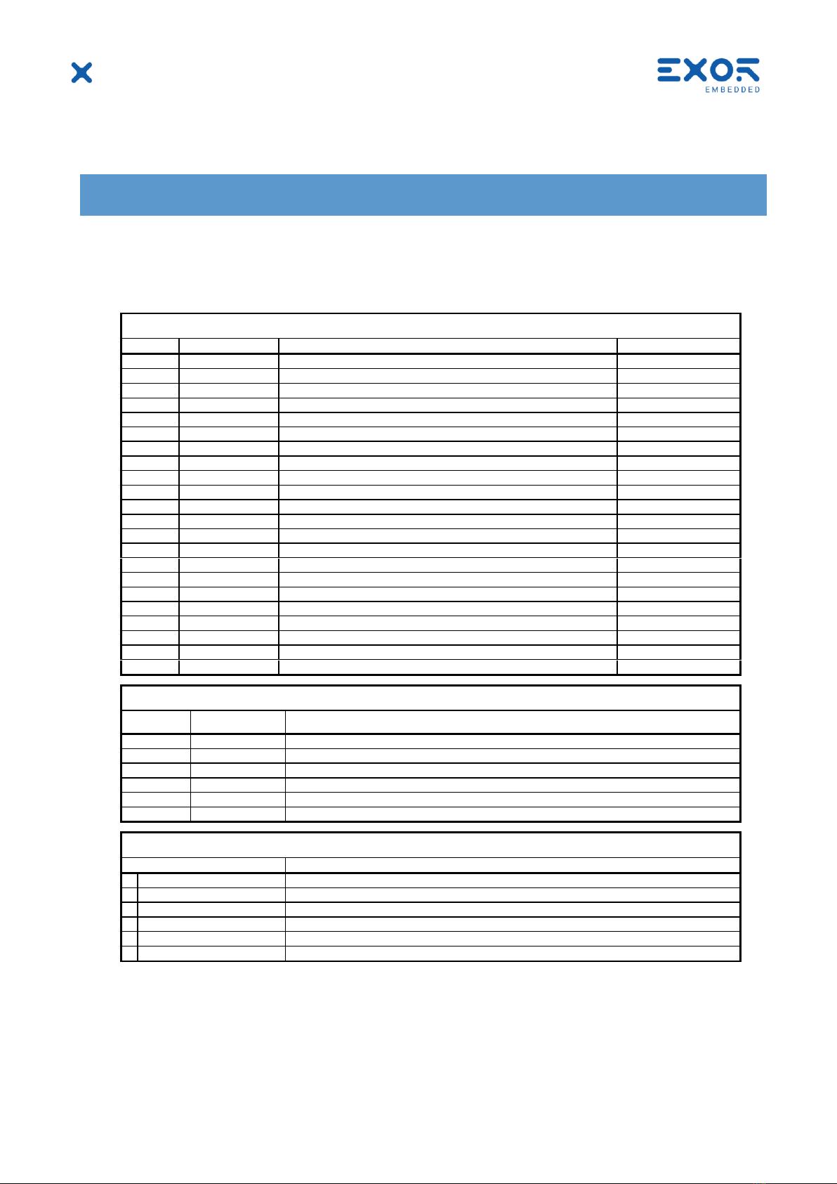
TABLE OF CONTENTS
1Introduction.................................................................................................................................4
2Description ..................................................................................................................................4
2.1 Key Features ......................................................................................................................4
3Kit Contents.................................................................................................................................4
4This is GigaSOM.........................................................................................................................5
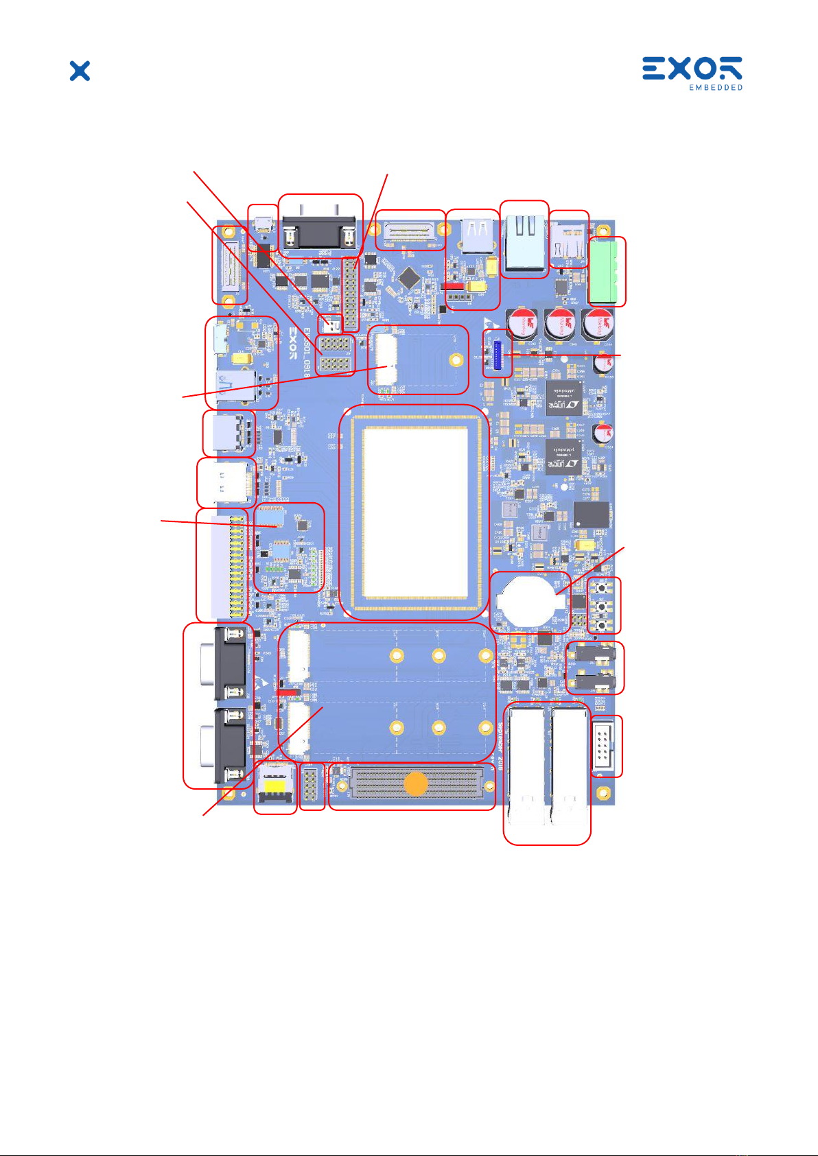
5Carrier connectors and interfaces ..........................................................................................6
6Getting started............................................................................................................................7
6.1 Onboard Memory (LPDDR4) ...........................................................................................7
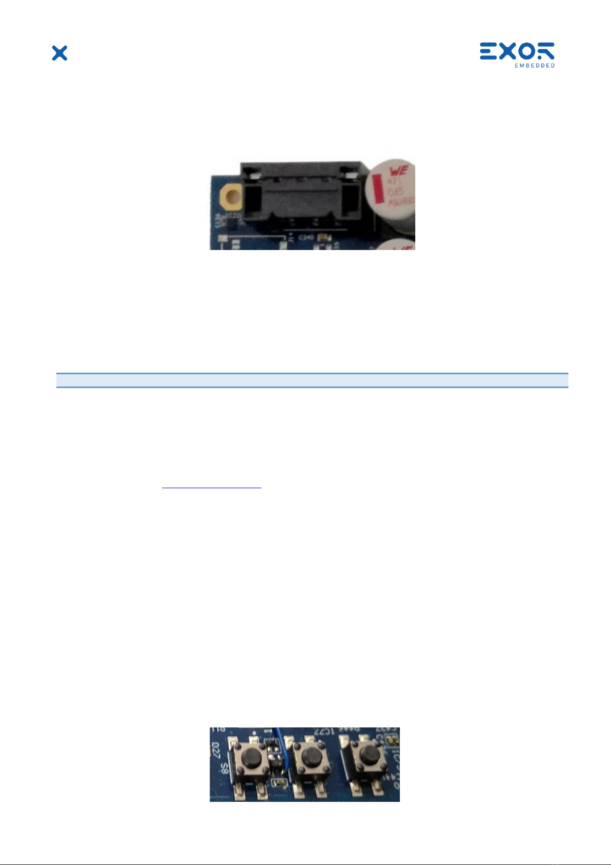
6.2 Buttons................................................................................................................................7
6.3 USB ......................................................................................................................................8
6.4 Display.................................................................................................................................8
6.4.1 Display port (DP)..................................................................................................8
6.4.2 HDMI out ...............................................................................................................8
6.4.3 Dual channel LVDS port......................................................................................8
6.5 Ethernet...............................................................................................................................9
6.6 Micro SD card ....................................................................................................................9
6.7 SIM card..............................................................................................................................9
6.8 Audio interface ..................................................................................................................9
6.9 SPI interface.................................................................................................................... 10
6.10LPC interface .................................................................................................................. 10
6.11Camera CSI interface .................................................................................................... 10
6.12Serial interface................................................................................................................ 11
6.13Fan connector................................................................................................................. 11
6.14M.2 key B slots ............................................................................................................... 11
6.15M.2 key E slot.................................................................................................................. 12
6.16CAN interface.................................................................................................................. 12
6.17FMC connector............................................................................................................... 12
6.17.1 FMC JTAG.......................................................................................................... 13
6.18JTAG 13
6.19SFP+ 14
6.20SSW connector............................................................................................................... 14