Amfeltec Squid SKU-086-32e User manual

Contents
Squid PCIe Gen 3 Carrier Board™ for two M.2/NGSFF(NF1) SSD modules.
Hardware Manual, Revision 1.0
Page ii
Contents
1About this Document........................................................................................................................1
1.1 Purpose.................................................................................................................................1
1.2 Feedback..............................................................................................................................1
1.3 Revision History....................................................................................................................1
2General Description..........................................................................................................................2
2.1 Introduction...........................................................................................................................2
2.2 Package Contents.................................................................................................................2
3Features...........................................................................................................................................6
3.1 Features................................................................................................................................6
3.2 PCI Express Carrier board for 2 M.2 SSD modules interfaces connection..........................7
4Installation........................................................................................................................................8
4.1 Carrier board installation.......................................................................................................8
4.2 Carrier board Power ON.......................................................................................................8
5Hardware Description.......................................................................................................................9
5.1 Board Layout.........................................................................................................................9
5.2 LEDs...................................................................................................................................10
5.3 Connectors..........................................................................................................................10
6Appendix A:....................................................................................................................................11
6.1 Cables.................................................................................................................................11
7Appendix B: Limited warranty.........................................................................................................12
Figures
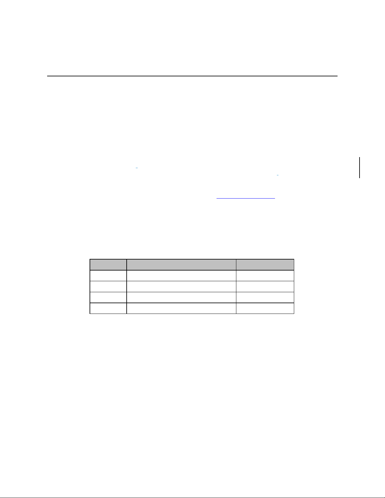
Figure 1: PCI Express Gen 3 Carrier Board for 2 M.2/NGSFF(NF1) SSD modules........................................3
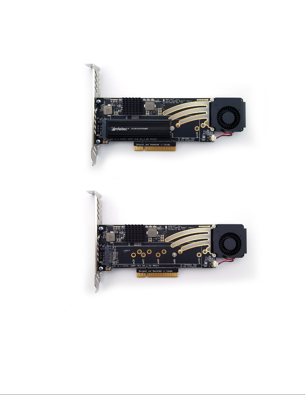
Figure 2: PCI Express Gen 3 Carrier Board for 2 M.2/NGSFF(NF1) SSD modules (top).................................4
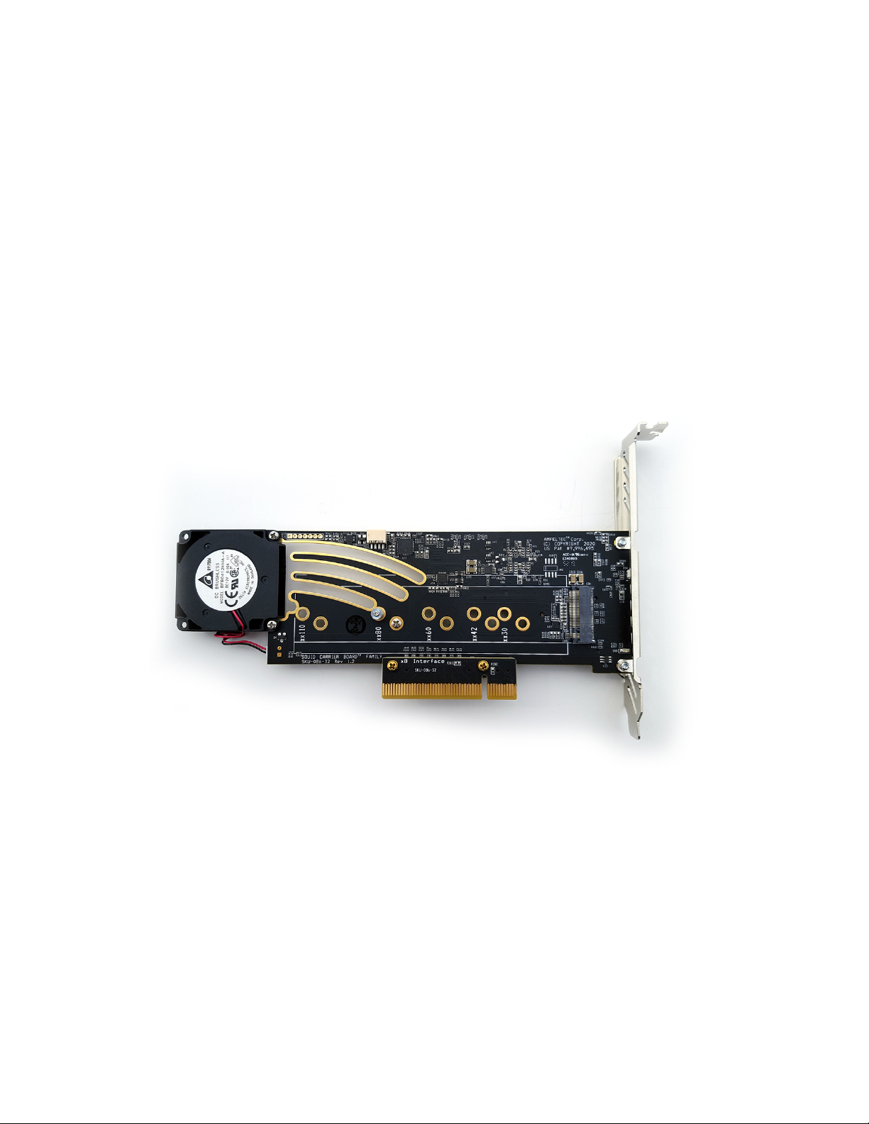
Figure 3: PCI Express Gen 3 Carrier Board for 2 M.2/NGSFF(NF1) SSD modules (bottom)..........................5
Figure 4: Carrier board PCI Express connection.......................................................................................7
Figure 5: PCI Express Carrier Board for M.2/NGSFF(NF1) modules layout...................................................9
Figure 6: SKU-043-37 USB terminal cable (optional) ..............................................................................11
Figure 7: SKU-043-41 USB terminal cable (optional) ..............................................................................11

Contents
Squid PCIe Gen 3 Carrier Board™ for two M.2/NGSFF(NF1) SSD modules.
Hardware Manual, Revision 1.0
Page iii
Tables
Table 1: PCI Express Carrier Board for M.2/NGSFF(NF1) SSD modules LEDs ...........................................10
Table 2: PCI Express Carrier Board for M.2/NGSFF(NF1) SSD modules connectors............................10


About this Document
Squid PCIe Gen 3 Carrier Board™ for two M.2/NGSFF(NF1) SSD modules.
Hardware Manual, Revision 1.0
Page 1
1 About this Document
1.1 Purpose
This document describes hardware installation, features, specification and operation of the
Squid
PCI Express Gen 3 Carrier Board™ for two M.2/NGSFF(NF1) SSD modules from AMFELTEC
Corporation
.
1.2 Feedback
AMFELTEC Corp.makes every effort to ensure that the information contained in this document is
accurate and complete at time of release. Please contact AMFELTEC Corp.if you find any errors,
inconsistence or have trouble understanding any part of this document.
To provide your feedback, please send an email to support@amfeltec.com
Your comments or corrections are greatly valued in our effort for excellence and continued
improvement.
1.3 Revision History
Rev. No. Description Rev. Date
1.0 Initial Release. May 5, 2020

General Description
Squid PCIe Gen 3 Carrier Board™ for two M.2/NGSFF(NF1) SSD modules.
Hardware Manual, Revision 1.0
Page 2
2 General Description
2.1 Introduction
Squid PCI Express family is a series of PCI Express Carrier Boards designed for storage
expansion of any desktop computer or embedded appliance. Squid family expands a
motherboard’s PCI Express with multiple full/half size MiniPCI Express or multiple
M.2/NGSFF(NF1) PCI Express SSD modules.
The carrier board is a half-height PCIe board, and occupies the space equal to a standard one-
slot wide PCIe board, as defined by the PCIe Specification. It is located in the middle of
motherboard’s PCIe slot, and connects to the motherboard via exchangeable x8 or x4 PCIe
upstream adapters. This unique PCI Express structure (US. Pat #9,996,495) allows for
allocating of multiple PCIe M2/NGSFF(NF1) modules on the top and bottom sides of the
carrier board without violation PCI Express Specification.
This carrier board has two M.2 (M-key) circuits. One circuit are placed on the top
(component) side of the board, and another circuit is placed on the bottom (soldering) side
of the board. Each circuit support any M.2/NGSFF(NF1) PCI express module (M-key)
with a standard length of 30, 42, 60, 80 mm and 110 mm (xx30/xx42/xx60/xx80 and
xx110) and width up to 32 mm.
This board has real-time performance and temperature monitoring via USB port.
2.2 Package Contents
PCI Express Gen 3 Carrier Board for 2 M.2 SSD modules package (depending on the SKU part
number) includes the following parts:
1. PCI Express Gen 3 Carrier Board for 2 M.2 modules (Figure 1,2,3)
2. x4 or x8 PCI Express Adapters
3. Full or half size PCI Express bracket
4. USB terminal cable SKU-043-37 (optional)

General Description
Squid PCIe Gen 3 Carrier Board™ for two M.2/NGSFF(NF1) SSD modules.
Hardware Manual, Revision 1.0
Page 3
Figure 1: PCI Express Gen 3 Carrier Board for 2 M.2/NGSFF(NF1) SSD modules

General Description
Squid PCIe Gen 3 Carrier Board™ for two M.2/NGSFF(NF1) SSD modules.
Hardware Manual, Revision 1.0
Page 4
Figure 2: PCI Express Gen 3 Carrier Board for 2 M.2/NGSFF(NF1) SSD modules (top).

General Description
Squid PCIe Gen 3 Carrier Board™ for two M.2/NGSFF(NF1) SSD modules.
Hardware Manual, Revision 1.0
Page 5
Figure 3: PCI Express Gen 3 Carrier Board for 2 M.2/NGSFF(NF1) SSD modules (bottom).

Features
Squid PCIe Gen 3 Carrier Board™ for two M.2/NGSFF(NF1) SSD modules.
Hardware Manual, Revision 1.0
Page 6
3 Features
3.1 Features
•Easy ‘Plug and Play” installation. No drivers needed. Transparent to the operation system.
•Compatible to any motherboard.
•Supports up to two M.2 or NGSFF(NF1) PCI Express SSD modules (M-key)
•Supports any modules with 30, 42, 60, 80 mm and 110 mm length, and up to 32 mm in
width.
•x4 PCIe Gen 3 (8.0 Gbps) downstream connection to each M.2 circuit.
•x8 or x4 PCIe Gen 3 (8.0 Gbps) upstream motherboard connection via exchangeable x8 or
x4 PCI Express upstream Adapter.
•Occupies space equal to standard one-slot wide PCIe board defined by PCIe Specification.
•Easily removable cooling fan.
•Performance and temperature monitoring during operation; cooling fan speed control.
•Real-time transmission of carrier board & modules’ status to host computer via USB
connection. (optional)
•Meets PCIe 3.0 and M.2 1.1 Specifications.
•Dimension:
-Without Cooling Fans - 67 x 145 mm
-With Cooling Fans - 67 x 180 mm.
•RoHS compliant.

Features
Squid PCIe Gen 3 Carrier Board™ for two M.2/NGSFF(NF1) SSD modules.
Hardware Manual, Revision 1.0
Page 7
3.2 PCI Express Carrier board for 2 M.2 SSD
modules interfaces connection.
Figure 4: Carrier board PCI Express connection.

Installation
Squid PCIe Gen 3 Carrier Board™ for two M.2/NGSFF(NF1) SSD modules.
Hardware Manual, Revision 1.0
Page 8
4 Installation
4.1 Carrier board installation
Following steps provide the exact sequence that needs to be followed in order to properly install
the Amfeltec PCIe Carrier Board:
oTurn OFF computer before installation.
oRemove the chassis cover from the computer.
oLocate an unused PCI express slot and remove the corresponding slot cover from computer
chassis. For maximum performance, it is preferable to use x16 PCI express slot that has
a direct connection to CPU.
oInsert the carrier board into the appropriate PCI express slot, and attach its bracket to the
computer chassis with a screw.
o(optionally) install USB monitoring cable SKU-043-37. (Connector J53 on the board and
the 10-pin USB connector on the motherboard)
oPut the chassis cover back on the computer.
oTurn ON the computer.
4.2 Carrier board Power ON
During power ON, the Carrier board runs self-test that include:
• Upstream and downstream PCI express connection verification
• Checking status LEDs
• Cooling fans operation
After power ON the operation status test result is shown on D53(red) and D54(green) LEDs:
D53 is solid ON
Power ON Carrier Board verification status
D54 is solid ON
Power ON Carrier Board verification status

Hardware Description
Squid PCIe Gen 3 Carrier Board™ for two M.2/NGSFF(NF1) SSD modules.
Hardware Manual, Revision 1.0
Page 9
5 Hardware Description
5.1 Board Layout
Figure 5: PCI Express Carrier Board for M.2/NGSFF(NF1) modules layout

Hardware Description
Squid PCIe Gen 3 Carrier Board™ for two M.2/NGSFF(NF1) SSD modules.
Hardware Manual, Revision 1.0
Page 10
5.2 LEDs
Name Ref.
Des.
Color
Usage
RESET D39 RED Global PCI Express RESET signal from motherboard
UPSTREAM D40 GREEN Upstream PCI Express Link status.
LINK1 D41 GREEN Status of the downstream x4 PCIe Link to U28
LINK2 D42 GREEN Status of the downstream x4 PCIe Link to U26
Table 1: PCI Express Carrier Board for M.2/NGSFF(NF1) SSD modules LEDs
5.3 Connectors
Ref. Des. Type Usage
J36, J37
Connectors
Connection to the x4 or x8 PCI Express Adapter
J50
Connector
Removable Cooling Fan Connection
U28
M.2 connectors
(M key)
M.2 add-in modules connection
(top side)
U26
M.2 connectors
(M key)
M.2 add-in modules connection
(bottom side)
Table 2: PCI Express Carrier Board for M.2/NGSFF(NF1) SSD modules connectors

Appendix A:
Squid PCIe Gen 3 Carrier Board™ for two M.2/NGSFF(NF1) SSD modules.
Hardware Manual, Revision 1.0
Page 11
6 Appendix A:
6.1 Cables
Figure 6: SKU-043-37 USB terminal cable (optional)
Figure 7: SKU-043-41 USB terminal cable (optional)
Both SKU-043-37 and SKU-043-41 Terminal cables is using to support Real-time performance
and temperature monitoring option via USB connection. This monitoring option requires Silicon
Labs CP2102 bridge driver installation
https://www.silabs.com/products/development-tools/software/usb-to-uart-bridge-vcp-drivers

Appendix B: Limited warranty
Squid PCIe Gen 3 Carrier Board™ for two M.2/NGSFF(NF1) SSD modules.
Hardware Manual, Revision 1.0
Page 12
7 Appendix B: Limited warranty
AMFELTEC Corporation does not warrant that the operation of the hardware, software or
firmware products will be uninterrupted or error free. AMFELTEC products are not intended to be
used as critical components in life support systems, aircraft, military systems or other systems
whose failure to perform can reasonably be expected to cause significant injury to humans.
AMFELTEC expressly disclaims liability for loss of profits and other consequential damages
caused by the failure of any product which would cause interruption of work or loss of profits,
such as shipboard or military attachment.
THIS LIMITED WARRANTY IS IN LIEU OF ALL OTHER WARRANTIES, EXPRESSED OR
IMPLIED. THE WARRANTIES PROVIDED HEREIN ARE BUYER’S SOLE REMEDIES. IN
NO EVENT SHALL AMFELTEC CORPORATION BE LIABLE FOR DIRECT, SPECIAL,
INDIRECT, INCIDENTAL OR CONSEQUENTIAL DAMAGES SUFFERED OR INCURRED
AS A RESULT OF THE USE OF, OR INABILITY TO USE THESE PRODUCTS. THIS
LIMITATION OF LIABILITY REMAINS IN FORCE EVEN IF AMFELTEC CORPORATION
IS INFORMED OF THE POSSIBILITY OF SUCH DAMAGES.
Some states do not allow the exclusion or limitation on incidental or consequential damages, so
the above limitation and exclusion may not apply to you. This warranty gives you specific legal
rights, and you may also have other rights which vary from state to state.
Table of contents
Other Amfeltec Carrier Board manuals