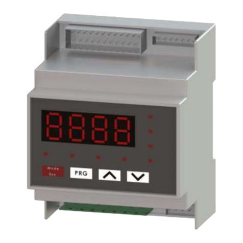
Engineered air EngA M-TRAC1 Mounting instructions

A
IOM-55 May 2019
USER OPERATION
MANUAL
FOR
M-TRAC1
DIRECT FIRED HEATING CONTROLLER
UNIT MODEL NO. _________________
UNIT SERIAL NO. _________________
SERVICED BY: ___________________
TEL. NO: ________________________
CANADIAN
HEAD OFFICE
AND FACTORY
USA
HEAD OFFICE
AND FACTORY
CANADIAN
EASTERN FACTORY
1401 HASTINGS CRES. SE
CALGARY, ALBERTA
T2G 4C8
Ph: (403) 287-2590
Fax: 888-364-2727
32050 W. 83rd STREET
DESOTO, KANSAS
66018
Ph: (913) 583-3181
Fax: (913) 583-1406
1175 TWINNEY DRIVE
NEWMARKET, ONTARIO
L3Y 5V7
Ph: (905) 898-1114
Fax: (905) 898-7244
SALES OFFICES ACROSS CANADA AND USA
Retain instructions with unit and maintain in a legible condition.
Please give model number and serial number when contacting
factory for information and/or parts.
www.engineeredair.com

A M-TRAC1
IOM-55 May 2019
2
M-TRAC1
The M-TRAC1 has been certified by Intertek (ETL) for use with Engineered Air appliances only.
It has been evaluated to CSA C22.2 No. 24 Temperature-Indicating and Regulating Equipment
and UL 873 UL Standard for Safety Temperature-Indicating and Regulating Equipment. This is a
User Operation Manual and therefore not subject to evaluation.
If any errors or omissions are noted please contact the nearest Engineered Air Technical Service
Department.
To ensure warranty is honored, only qualified personnel should be employed for service and
troubleshooting. If further information is required please contact the nearest Engineered Air
office.
There are two sets of electrical drawings and unit function sheets provided with the appliance.
One set is in an envelope which also contains the Operation, Installation and Maintenance
manual(s). This package is for copying, then should either be returned to the appliance or
stored in a safe place. The other set is attached to the control panel door and should never be
removed.
Please report any omissions to the national service manager.
Warning:
Improper installation, adjustment, alteration, service or maintenance can cause
property damage, injury or death. Read the installation, operating and
maintenance instructions thoroughly before installing or servicing this equipment.
Warning:
This unit is connected to high voltages. Electrical shock or death could occur if
instructions are not followed. This equipment contains moving parts that can start
unexpectedly. Injury or death could occur if instructions are not followed. All
work should be performed by a qualified technician. Always disconnect and lock
out power before servicing. DO NOT bypass any interlock or safety switches under
any circumstances.

A M-TRAC1
IOM-55 May 2019
3

A M-TRAC1
IOM-55 May 2019
4
TABLE OF CONTENTS
INTRODUCTION .............................................................................................................................. 5
CONTROLLER RATINGS................................................................................................................... 5
CONTROLLER DESCRIPTION ........................................................................................................... 6
TERMINALS................................................................................................................. 6
DIP SWITCHES ........................................................................................................... 7
INDICATION AND DIAGNOSTIC LIGHTS................................................................... 7
ADJUSTMENT POTS .................................................................................................. 8
MULTIMETER TEST POINTS............................................................................................................ 8
MAXIMUM DISCHARGE SET POINT LIMIT SETUP (SP LMT)................................... 8
CALCULATED SETPOINT (SPC) ................................................................................ 8
DISCHARGE TEMPERATURE (DTEMP) .................................................................... 9
PROFILE PLATE VELOCITY....................................................................................... 9
LOCKOUT RESET ....................................................................................................... 9
CONTROL ...................................................................................................................................... 10
SYSTEM TIMING ....................................................................................................... 10
DISCHARGE AIR SETPOINT .................................................................................... 10
DISCHARGE AIR SENSOR....................................................................................... 10
LOW LIMIT................................................................................................................. 10
DAMPER CONTROL ................................................................................................. 11
BLOWER CONTROL ................................................................................................. 11
BURNER CONTROL.................................................................................................. 11
PROFILE PLATE VELOCITY SENSING SYSTEM .................................................... 12
TEMPERATURE RESET................................................................................................................... 12
MAKE / BREAK THERMOSTAT ................................................................................ 12
2 –10 Vdc SIGNAL .................................................................................................... 12
OPERATION................................................................................................................................... 13
EXHAUST FAN INTERLOCKING .............................................................................. 13
MODULATING VALVE LIGHT OFF POSITION ......................................................... 13
LOW FIRE.................................................................................................................. 13
CALIBRATION................................................................................................................................ 13
SETPOINT (SPC)....................................................................................................... 14
DISCHARGE AIR TEMPERATURE (DTEMP) ........................................................... 14
PROFILE VELOCITY ................................................................................................. 15
2-10 VDC RESET SET UP......................................................................................... 15
SERVICE......................................................................................................................................... 15
SERVICE MODE........................................................................................................ 15
SETPOINT REMOTE WIRING................................................................................... 15
AIR PRESSURE SENSOR ........................................................................................ 15
INPUT CONTACTS BY OTHERS .............................................................................. 16
BMS SENSOR LOCATION ........................................................................................ 16
M-TRAC1 LOCK OUT DESCRIPTION....................................................................... 17
SENSOR TABLE........................................................................................................ 17
FAN OPERATION FLOWCHART..................................................................................................... 18
HEAT OPERATION FLOWCHART................................................................................................... 19

A M-TRAC1
IOM-55 May 2019
5
INTRODUCTION
The M-TRAC1 is a discharge air temperature controller of large (BTUH) single volume direct-
fired Engineered Air equipment, using 120 Vac safety shut off valves, and operating a
modulating ball valve actuator.
The information used in this manual should be used in conjunction with the unit function
sheet(s) and the HE series Installation, Operation, and Maintenance manual.
The M-TRAC1 is designed to control only Engineered Air equipment. Various upgrades and
improvements have been made over time. Always include any suffix letters and numbers for
troubleshooting and/or replacement. All M-TRAC1 models are backwards compatible, however
some additional wiring may be required. M-TRAC1 controllers with a ( - P ) designation are
designed for propane fuel.
Note: It is necessary that all of the remote wiring and controls be complete and operational
before starting the appliance.
CONTROLLER RATINGS
Power requirements: 24 Vac, 40 VA.
Contact Rating: 120V 3A inductive
0-10 Vdc input impedance: 2 k
Environment: -40 to 120°F (-40 to 50°C) non-condensing.
Fuse Rating: 1.25 GDC slow-blow

A M-TRAC1
IOM-55 May 2019
6
CONTROLLER DESCRIPTION
TERMINALS TABLE 1
Terminal
Description
HD
0-10 Vdc output to ball valve actuator
Q1
Input terminal for single discharge sensor
Q2
Input terminal for two discharge sensors wired in series
U
Sensor common
SP
Output from the built in set point POT.
RP
Positive supply for a remote set point POT.
RS
Return from the remote set point POT.
S
Setpoint enable
+ / -
2 to 10 Vdc input
PF
Not used
H
24 Vac hot
N
24 Vac neutral
FS
Fan switch input
HS
Heat switch input
LMT
Input from safety limit (high limit)
VN
Neutral for the 120 Vac Main gas valve feedback
VFB 120
Hot for the 120 Vac Main gas valve feedback
FR
Flame relay control
CFR
Flame relay control common
PV1 / PV2
Pilot Valve control contacts
C
Input power supply to feed DM, SA and AL outputs
DM
Damper enable output
SA
Supply blower output
AL
Alarm output or Reverse interlock control output

A M-TRAC1
IOM-55 May 2019
7
DIP SWITCHES
The M-TRAC1 options are configured by DIP switch selection and/or wiring connections. DIP
switch settings are noted on the internal wiring diagram, and should not be altered.
TABLE 2
DIP SW
Description
10
Disable Auto Heat Switch. If enabled the M-TRAC1 will monitor the discharge air
temperature and disable the heat if the temperature is constantly greater than
the Setpoint (> 3˚F).
9
Extended Profile Velocity Range. Allows the M-TRAC1 to be compatible with
older equipment.
8
Service Mode. Enable to manually control the firing rate.
7
Air Priority Program. See Blower Control.
6
16 Second Pre-purge. Heating will delay on after fan starts.
5
Slow Opening Valve. See Modulating Valve Light Off Position.
4
Disable Open Sensor Checking. See Discharge Air Setpoint.
3
Disable Low Limit. See Low Limit.
2
Alarm contact to be used for reverse interlock. See Reverse Interlock.
1
2-10 Vdc Set Point Reset. See Temperature Reset.
Note: Table based on model M-TRAC 1.4.3
INDICATION AND DIAGNOSTIC LIGHTS
There are 5 status lights on the M-TRAC1 labeled A to E. They operate in 4 patterns: an
irregular flash (.. __ .. __ ..), fast flash (…….), slow flash (. . .), or constantly on (_____).
TABLE 3
IRREGULAR
FAST
SLOW
ON
LIGHT
System Lockout
System Lockout
System
Problem
System
Ok
A –GREEN
Wiring Or Flame
Relay Problem
Prepurge Or Valve
Positioning Delay
Limit Open
Ignition
Attempt
B –RED
Air Flow Or M-TRAC
Problem
Air Velocity Very Low
Air Velocity Too
Low
Air Velocity Too
High
C –RED
Service Mode
Ignition Failure
Heat Switch Open
Burner On
D –RED
Open Discharge
Sensor
Discharge Temp Low
Fan Switch Open
Damper Open
Delay
E –RED

A M-TRAC1
IOM-55 May 2019
8
ADJUSTMENT POTS
There are a number of setting and calibration potentiometers (POT’s) located on the face of the
M-TRAC1. Modifications to these should only be performed by experienced and qualified
personnel.
TABLE 4
POT
Description
SP LMT
Limits the maximum discharge temperature set point.
CAL DTEMP
Discharge air sensor temperature calibration.
SP CAL
Setpoint dial calibration.
MIN FIRE
Adjusts the minimum valve output for low fire.
SERVICE POT
Manually sets burner firing rate for service. Located just above the centre.
When the service switch is on, this POT can be used to adjust the
modulating gas valve from low to high fire. When the service DIP switch is
on, light ‘D’ blinks irregularly.
2-10 Vdc
RESET RATIO
Sets the reset temperature range. This adjusts the amount of reset range
the 2-10 Vdc room thermostat will have. This allows an adjustment band
between 5°F and 50°F (3°C and 28°C).
PROFILE
VELOCITY
Allows a narrow adjustment for Profile pressure set point.
MULTIMETER TEST POINTS
The M-TRAC1 has readout test points for discharge air temperature, discharge set point and
profile plate velocity status. Temperature readings are indicated by Vdc referenced to ground.
MAXIMUM DISCHARGE SET POINT LIMIT SETUP (SP LMT)
Regulations, design or authorities having jurisdiction may limit the maximum discharge air
temperature the appliance is allowed to reach. This may be set by the potentiometer SP LMT,
which is located below and to the right of the M-TRAC1 discharge set point knob. Vdc readout
= °C / 10. See Table 5.
CALCULATED SETPOINT (SPC)
The SPC measurement point is located just below the M-TRAC1 set point knob. This
temperature is the current operating set point after all applicable temperature resets have
been applied to primary or base set point. Vdc readout = °C / 10. See Table 5.

A M-TRAC1
IOM-55 May 2019
9
DISCHARGE TEMPERATURE (DTEMP)
The DTEMP measurement point is located on the top left corner of the M-TRAC. The voltage
reading relates to the actual temperature of the discharge sensor.
Table 5
Voltage (Vdc)
˚C
˚F
1
10
50
1.5
15
59
2
20
68
2.5
25
77
3
30
86
3.5
35
95
4
40
104
NOTE: Sensor accuracy is diminished at temperatures greater than those noted in this table.
PROFILE PLATE VELOCITY
The profile plate has been factory set for the airflow shown in the submittal record.
The profile plate air velocity status can be determined by reading the DC volts measured
between the profile measurement point (located close to terminal S) and terminal N. When the
profile velocity is optimum, the reading is 6 Vdc. For other voltage readings see Table 6.
Note that if the airflow is reduced below safe operating conditions there are delays built into
the M-TRAC1 that will shut off the flame within 45 seconds.
TABLE 6
Test Point Reading
Status
Result
Below 0.8 volts
Very low or no
airflow
Unit lockout
Between 0.8 and 4.0
volts
Low airflow
If the burner is already off it is disabled. If the
burner is on, variable timed lockout.
Between 4.0 and 7.0
volts
Operating range
Normal
Over 7.0 volts
High airflow
If the burner is already off it is disabled. If the
burner is on, variable timed lockout.
M-TRAC models with a ( -P ) designation (propane) will operate with a slightly higher airflow.
LOCKOUT RESET
To reset the M-TRAC1 from a lockout condition push the “Reset Push Button” located just
above the DIP switch block. If the M-TRAC1 looses power while locked out, the status codes

A M-TRAC1
IOM-55 May 2019
10
(reason for the lockout) will be lost. When power is resumed the M-TRAC1 will remain locked
out, but only green LED flashing irregularly.
CONTROL
SYSTEM TIMING
Damper opening delay: Depends on type of damper actuator used.
Blower startup: 54 seconds after terminal FS is energized.
Low Limit bypass: 4.5 minutes from initial startup, 50 seconds nuisance timer.
Trial for ignition: 30 sec.
DISCHARGE AIR SETPOINT
The M-TRAC1 is a discharge air temperature controller with a built in face mounted set point
knob (that is activated by connecting terminal S to SP). Optionally, the M-TRAC1 is available
with a remote set point, with varying set point ranges. When a remote setpoint is provided, the
M-TRAC1 face mounted set point will have no effect.
Additional methods of resetting the discharge air temperature setpoint may be used. Refer to
the unit function and electrical drawing.
DISCHARGE AIR SENSOR
The M-TRAC1 is designed to use either a single or dual discharge sensors, wired in series. Dual
sensors are always used in equipment with temperature rise over 100˚F (55°C) or with dual
fans. In most applications the discharge air sensor(s) is located in the supply blower outlet.
The discharge air sensor also serves as a low limit (or freeze protection) sensor. The part
number of the sensor is noted on the electrical drawing.
The M-TRAC1 automatically checks the discharge air sensor(s). If the M-TRAC1 reads an open
sensor it will disable temperature control and reduce the firing rate to low fire, then shutdown
the appliance. Open sensor checking may be disabled by switching on DIP switch #4.
LOW LIMIT
The M-TRAC1 control is typically configured so that the discharge air temperature sensor also
performs the function of a low limit or freeze stat. If DIP switch 3 is ‘off’ the low limit function
is enabled. If the discharge temperature falls below 40˚F (4°C) the appliance will shut down and
the LED for low discharge temperature will begin flashing. On initial startup the M-TRAC1 will
internally bypass the low limit for 3 minutes. After this time, the low limit discharge
temperature must be below the low limit setpoint (40°F / 4°C) for 50 seconds before the
M-TRAC1 will shut the appliance off.
If DIP switch 3 is ‘on’, the low limit safety function is disabled.

A M-TRAC1
IOM-55 May 2019
11
DAMPER CONTROL
The inlet damper actuator(s) is enabled through output terminal DM. The M-TRAC1 allows time
for the dampers to open prior to starting the supply blower.
BLOWER CONTROL
The M-TRAC1 uses output terminal SA to control the supply air fan. There are, however, a
number of internal and/or external components that may be required to be functional prior to
starting the blower. Proof of air flow is confirmed by the profile pressure sensor.
In some applications continuous airflow is more important than temperature control. The
M-TRAC1 has two blower control program options. They are referred to as airflow priority, and
comfort priority. See Table 7 for the differences between the two priorities. Priority type is
selected by DIP switch 7.
For the comfort priority program, minimum airflow is defined as 60% of required airflow.
Airflow priority is defined as 40% of required airflow.
TABLE 7
Priority Level
Status
Comfort
Air Flow
Heat switch off.
Low airflow
Lock out in 50 seconds.
Blower will remain on until the
discharge air temperature falls
below 40˚F (4°C).
Flame failure, with
discharge temperature
greater than 40°F (4˚C).
Burner and blower off.
Burner off, blower continues to run.
Heat on, but sensing a high
air velocity condition.
Unit will shutdown after
60 seconds.
Burner will lockout after 60
seconds. Blower will remain on
until the discharge air temperature
falls below 40˚F (4°C).
Heat on, with the high limit
control open.
Unit will shutdown after 4
seconds.
Burner will lockout after 4 seconds.
Blower will remain on until the
discharge air temperature falls
below 40˚F (4°C).
BURNER CONTROL
The M-TRAC1 outputs a 0 to 10 Vdc signal to a modulating actuator / ball valve assembly to
control and maintain a defined discharge air temperature setpoint. 10Vdc is the maximum
firing rate (high fire).

A M-TRAC1
IOM-55 May 2019
12
PROFILE PLATE VELOCITY SENSING SYSTEM
The M-TRAC1 has a built in profile pressure sensor to prove and monitor air flow across the
burner. This allows the burner to operate safely and efficiently by proving the airflow is within
proper air velocity limits.
The profile pressure sensor has three non-adjustable air settings: 40, 60 and 120% of normal
airflow. These perform the equivalent function of the high (120%) and low (60%) velocity air
switches while providing an additional very low (40%) velocity for use in process applications,
when providing air is more crucial than temperature control.
The normal profile plate pressure drop is 0.48”w.c.
TEMPERATURE RESET
MAKE / BREAK THERMOSTAT
The set point can be configured for two-level discharge air temperature control, initiated by a
override contact or space mounted, single stage thermostat, with the second (upper) level
adjustable from 75˚(24°C) to 170˚F (77°C) by the SP LMT POT.
2 –10 Vdc SIGNAL
The set point can be adjusted linearly upwards from 5°F to 50 °F (3°C to 28°C) from a 2-10 Vdc
BMS input on terminals - and +. When equipped with a 2 to 10 Vdc room thermostat, this
option becomes a linear room reset. The discharge set point dial, either face mounted or
remote mounted, is the minimum set point. The maximum reset amount is adjusted by the 2-
10VDC RESET RATIO POT located beside terminals RS and RP.
RESET EXAMPLE
SP LMT set at 95˚F, Dial set point set at 50˚F.
2-10 Vdc reset ratio POT adjusted to give 30˚F reset at 10 Vdc.
The resulting control will be:
At 0-2 Vdc = 50˚F discharge
At 6 Vdc = is ½ of the reset authority. Half of 30˚F equals 15˚F, therefore the discharge setpoint
will be at 65˚F (50° + 15° = 65°). At 10 Vdc = full reset. Discharge will be at 50° + 30° = 80˚F.
This will not be limited by the SP LMT (at 95°F), unless the setpoint dial is turned up more than
15°F.

A M-TRAC1
IOM-55 May 2019
13
OPERATION
EXHAUST FAN INTERLOCKING
There are a number of different exhaust interlocking options available. Always refer to the
wiring diagram and unit function sheet to determine the exact type of interlocking used.
The AL output contact may be switched from an alarm output to a exhaust fan enable output
contact for control of reverse interlock control systems (DIP sw #2). In this mode terminal AL
will close on proof of supply air flow.
MODULATING VALVE LIGHT OFF POSITION
The appliance the M-TRAC1 is controlling may use either a fast opening (solenoid) safety shut
off valve, or a slow opening (hydraulic) valve. To ensure the modulating valve is positioned
correctly for initial ignition and avoid high fire ignition, DIP switch 5 is factory set depending on
the type of safety shut off valve.
The M-TRAC1 is designed to ignite the burner at approximately 40% of full fire (non-adjustable).
The positioning time delay allows the modulating valve actuator time to reach the correct light
off position before an ignition attempt is made.
Set DIP switch 5 to “on” when ever the main gas valve is a slow opening. For fast opening valve,
set DIP switch 5 to the “off” position.
LOW FIRE
The M-TRAC1 may control a broad range of burner sizes, all with unique minimum firing rates
(low fire). The ball valve actuator minimum position voltage to set low fire is adjusted using the
built in M-TRAC1 POT labeled “Min Fire”. The POT can be adjusted from 0 to 40% of full fire,
and is located immediately to the right of the discharge air setpoint knob.
CALIBRATION
While the heater and M-TRAC1 is factory tested and calibrated, field conditions may affect
airflow and sensor readings. After making any calibration adjustment, it may take a few
minutes for the M-TRAC1 to reflect the changes. After this time, turn the appliance off for a
few seconds, and then turn the appliance back on. Re-confirm the calibration.

A M-TRAC1
IOM-55 May 2019
14
SETPOINT (SPC)
Check the wiring diagram to determine if the M-TRAC1 is using the face mounted setpoint dial
or an optional remote mounted setpoint dial. The most commonly used remote control panel
includes fan and heat on/off switches and a setpoint dial. A jumper will be installed across
terminals S and SP if the M-TRAC1 is using its built in setpoint dial.
1. Disable any external temperature resets (DIP switch 1 off) or lower the room thermostat
settings so there is no call for additional heat.
2. Use a voltmeter to measure the Vdc output on the SPC measurement point.
3. Compare to the Setpoint dial and adjust the SP CAL POT (located near the face mounted
setpoint dial) so they match (1 Vdc = 10°C).
4. Turn DIP switch 1 on, or return the room thermostat to its normal position.
Note: If the adjustments have no effect on the discharge temperature, the set point may be
under the authority of the maximum set point limiting POT (SP LMT).
DISCHARGE AIR TEMPERATURE (DTEMP)
The discharge sensor must be located so that its temperature remains stable. Due to the
nature of direct fired appliance, the air temperature leaving the supply blower is often very
stratified. It is important to understand that the supply blower does not significantly mix the
air. As well, the stratification pattern will change with different firing rates, wind conditions,
ducting and blower configurations.
Field conditions may result in differences between the sensed temperature and the actual
temperature. Adjusting the location of the discharge sensor a few inches will often correct
temperature differences. If a section of duct is connected to the discharge opening, the sensor
may be moved downstream up to 10 ft. (3 meters). Moving the sensor too far downstream
may result in sensing lag, which could compound control error.
1. Accurately measure the temperature at the discharge air sensor.*
2. Compare the temperature to the DTEMP test point voltmeter reading.
3. Match the readings by adjusting the CAL DTEMP POT (located near terminal Q1,
1 Vdc = 10°C).
* The discharge sensor may be temporarily replaced with a resistor to confirm calibration.
Refer to the Sensor Table, or use a 1kΩ resistor for 21.1°C (70°F) or a 2 kΩ resistor is using dual
sensors (using terminal Q2). Do not leave the resistor in place for normal operation!

A M-TRAC1
IOM-55 May 2019
15
PROFILE VELOCITY
Profile velocity test point readings outside the 4.0 -7.0 Vdc range generally indicate improper
airflow through the heater, not a problem with the M-TRAC1. Before attempting to adjust the
profile velocity ensure the heater is operating at the required nameplate air volume.
The Profile Velocity POT is typically set to the ‘12’ o’clock position. Outside air temperature will
affect the pressure drop across the burner.
2-10 VDC RESET SET UP
1. The 2-10 VDC RESET RATIO POT is located beside terminal RP.
2. Turn off DIP switch 1 and turn the discharge set point knob (face mounted or remote) to
the minimum required set point.
3. Set the voltage across terminals + and –to maximum (10 volts).
4. Calculate the maximum required discharge temperature (°C) and divide by 10.
5. Turn on DIP switch 1 and adjust 2-10 Vdc reset POT ratio until the SPC voltage is equal to
the number calculated in the above step.
6. Adjust SP LMT until the voltage reading is the same as was recorded in step 5.
SERVICE
SERVICE MODE
Placing the M-TRAC1 into service mode allows for direct control of the burner firing rate. Once
the heater has started, the M-TRAC1 can be placed into the service mode by turning on DIP
switch 8. The service POT, located above the reset push button, will control the position of the
modulating valve to any position from low to high fire.
Note: The service mode does not bypass any safeties, heat or fan switches.
SETPOINT REMOTE WIRING
Impedance from long wiring runs may cause the setpoint to be out of calibration. Refer to the
setpoint calibration section if adjustment is required.
AIR PRESSURE SENSOR
The M-TRAC1 has an internally mounted air pressure sensor. Do not blow onto the pressure
ports –too much air pressure will damage it. The ports are fragile and can easily break.
During initial startup, the space the appliance is feeding may be under negative or positive
pressure. To accurately check the M-TRAC1 pressure sensor, remove the sensing tubes from
the M-TRAC1, while the fan is on, and the reading should be 0 Vdc.

A M-TRAC1
IOM-55 May 2019
16
Before making any modifications to the profile opening contact Engineered Air.
INPUT CONTACTS BY OTHERS
Mechanical relay (dry) input contacts must be used. The use of solid state relay’s (SSR’s) may
cause the M-TRAC1 to malfunction due to reverse leakage current when ‘open’.
BMS SENSOR LOCATION
The Engineered Air sensor must be calibrated to match its operation with the Engineered Air
control. Do not calibrate it to match BMS readout if one exists.
If there is a BMS sensor located in the discharge duct, that sensor must be mounted within ½
inch of the Engineered Air sensor.
Note: BMS (Building Management System) discharge air temperatures should never be used to
reset the temperature of the heater. Only use space or room mounted sensors.

A M-TRAC1
IOM-55 May 2019
17
M-TRAC1 LOCK OUT DESCRIPTION
Table 8
LED Code
Reasons
B Irregular
Faulty flame relay or wiring error. Ignition control and safety shut off valve
should be off (FR and CFR contact ‘open’, but receiving power to VFB120
indicating valve is still on.
Faulty flame relay or wiring error. FR and CFR contacts closes, but feedback
from safety shut off valve to VFB120 happening too fast.
B Slow
High limit open.
C Irregular
Air sensor self test. When the blower is off, the sensor reading should be below
0.7 Vdc.
Then the fan turns on, the air sensor reading should increase,
C Fast
Very low air flow. Sensed air flow is below 40%.
C Slow
Low air flow. Sensed air flow is below 60%.
C On
High air flow. Sensed air flow is over 120%.
D Fast
Ignition failure.
E Irregular
Open discharge air sensor. Sensor resistance should not exceed 1940, or 3450 Ω
for dual sensors.
E Fast
Low limit. Discharge temperature has fallen below 40°F (4°C).
SENSOR TABLE
Sensor Resistance Chart for TE 6100-960 and TE600EA3.
Table 9
˚C
˚F
Resistance Ω
˚C
˚F
Resistance Ω
˚C
˚F
Resistance Ω
-40
-40
597
4.4
40
877
48.9
120
1229
-34.4
-30
629
10
50
916
54.4
130
1279
-28.9
-20
661
15.6
60
958
60
140
1329
-23.3
-10
694
21.1
70
1000
65.6
150
1381
-17.8
0
728
26.7
80
1043
71.1
160
1433
-12.2
10
763
32.2
90
1088
76.7
170
1487
-6.6
20
800
37.8
100
1134
82.2
180
1542
-1.1
30
838
43.3
110
1181
87.8
190
1599
Note: Reference resistance is 1035 ohms at 77˚F. Resistance tolerances are ±0.05 to 0.15% at 77˚F.

A M-TRAC1
IOM-55 May 2019
18
FAN OPERATION FLOWCHART
- Main supply power ‘ON’.
- Service switch ‘ON’.
- Fire alarm contact ‘CLOSED’.
- Any additional contacts to terminal H ‘CLOSED’.
- 24Vac across terminals H and N.
Light C blinks
several times
very fast.
Fuse okay?
- Lights A and E slow blink.
Replace fuse.
No
Replace M-TRAC
Yes
No
- Enable fan switch and/or any
other interlocks to power terminal
FS (24Vac).
- Lights A and E ‘ON’.
- Flow control actuator moves to
ignition position.
- DM contact closes to enable damper
actuator.
Dampers
opening?
- Confirm output voltage at terminal DM.
- Check wiring connections to damper actuator.
- Confirm damper actuator is operational.
- Check damper assembly is free to move.
No
- Fan delays to allow dampers to open, then
starts.
Yes
Fan starts?
- Lights A and D slow blink (heat switch is still open).
- Light C will blink fast as fan speed increases, then off.
- Confirm output voltage on terminal SA.
- Check downstream wiring to motor starter.
Light C off?
End of fan section.
- Slow blink: air velocity too low.
- Fast blink: air velocity very low.
- Irregular blink: air flow or M-TRAC problem.
- Confirm air tubes are connected properly.
Yes
Yes
No
No
Yes
Check M-TRAC fuse.

A M-TRAC1
IOM-55 May 2019
19
HEAT OPERATION FLOWCHART
- Close heat switch and/or any other contacts or interlocks to power terminal
HS (24Vac).
- If system is reverse interlock the AL output will have closed when the supply
fan successfully started, and enabled the exhaust fan.
- Light D slow blink should now be Off.
Light B
irregular
blink?
Light B slow
blink?
Light B fast
blink?
Light B on?
- Wiring or flame relay problem. Check wiring into
terminals VFB120 and VN safety inputs.
- High limit safety contact is open. M-TRAC is
expecting 120Vac to terminal LMT.
- 16 second prepurge (DIP #6 on) or delay to set
modulating valve to ignition position.
No
Yes
Yes
Yes
Yes
No
No
No
- FR and CFR contacts close.
- PV1 and PV2 contacts close.
- Ignition control enabled.
Ignition sequence:
- Ignition control enables pilot valve and sparks at electrode.
- Pilot flame achieved and sensed.
- Ignition control outputs power to main valve control relay.
- Relay contact close to enable main valve(s) (SSOV).
- 120V feedback signal into terminals VFB120 and VN from main valve(s).
- Main burner lit from pilot flame.
- Ignition spark off.
- PV1 and PV2 contacts delay off to disable pilot valve. Ignition control is sensing
main burner only.
- Light D on (burner on).
End of heat section.
- Burner modulating valve enabled to
maintain discharge air temperature
setpoint, from 0-10Vdc output terminal
HD.
Table of contents
Other Engineered air Controllers manuals
