Nira i7r User manual

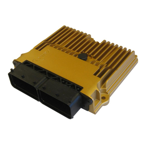
NIRA i7r
Handbook
NIRA i7r Handbook version A6, December 2015

© 2005-2015 Nira Control AB 2
© Copyright 2005-2015
This handbook is protected by copyright laws. It may not be redistributed in any form
without written consent of Nira Control AB.
Release 2015-12-01
The purpose of this handbook is to serve as a guide during installation and calibration
of NIRA i7r. Descriptions, content and specifications in this handbook may be
changed at any time. This handbook could contain errors –therefore it should not be
regarded as a definitive installation guide. Nira Control AB is not responsible for any
personal or property damages due to errors in this handbook, the professional
installing NIRA i7r is responsible for the installation.
Misuse of NIRA i7r and/or NIRA rk can cause severe personal injury and engine
damage. Nira Control AB is not responsible for any injuries, accidents or damages due
to misuse or ignorance.
Repairs of NIRA i7r, e.g. replacement of parts, will affect the safety of the product and
are not allowed under any circumstances. Nira Control AB is not responsible for any
problems, accidents etc, caused by non-approved parts or repairs not carried out by
Nira Control AB.
NIRA i7r must be installed by professional automotive technicians in accordance with
the instructions in this handbook, following good practice.
NIRA i7r is only intended for racing use and not for use on public roads. It is not
certified for use on vehicles subject to emission standards unless the appropriate
waivers have been issued. Please check with the relevant authorities for more
information.
NIRA rk is protected by applicable software copyright laws. You may not distribute
this software without the written consent of Nira Control AB. You may not copy this
software. Your purchase of NIRA i7r includes a single license to use NIRA rk together
with NIRA i7r.

© 2005-2015 Nira Control AB 3
1 Overview.................................................................................................................5
1.1 Content of your NIRA i7r Package...................................................................5
1.2 Glossary ...........................................................................................................6
1.3 NIRA i7r Functionality......................................................................................8
2 Combustion, Lambda and Measurement Principles ...............................................10
2.1 Relationship Between A/F, Lambda and Smoke...........................................10
2.2 Measurement Principles ................................................................................11
3 Installing NIRA i7r..................................................................................................14
3.1 Injectors .........................................................................................................15
3.2 Fuel Pressure Control Actuators ....................................................................16
3.3 Crank Position Sensor (CKP) and Trigger Wheel ...........................................17
3.4 Cam Position Sensor (CMP) ...........................................................................20
3.5 Acceleration Pedal Position (APP)..................................................................21
3.6 Manifold Absolute Pressure (MAP) and Intake Air Temp (MAT) ....................21
3.7 Engine Coolant Temperature Sensor (ECT)...................................................22
3.8 Manifold Air Temperature Sensor (MAT) .......................................................22
3.9 Lambda Sensor..............................................................................................23
3.10 Exhaust Gas Temperature. ............................................................................24
3.11 Boost Pressure Actuator ................................................................................25
3.12 Main Relay .....................................................................................................27
3.13 Pre Fuel Pump Relay......................................................................................28
3.14 Mounting NIRA i7r in the Vehicle ..................................................................29
4 NIRA rk Software ...................................................................................................29
4.1 Installation of NIRA rk ....................................................................................30
4.2 Getting Started..............................................................................................30
4.3 Using NIRA rk ................................................................................................33
4.4 Parameters.....................................................................................................36
4.5 PID Controllers ..............................................................................................47
4.6 Gauges ..........................................................................................................48
4.7 Logging .........................................................................................................51
4.8 Locking the i3d Data Set ...............................................................................54
4.9 FlexiPorts™ - Set up ......................................................................................54
5 Fuel Handling........................................................................................................56
5.1 Fuel Mass.......................................................................................................56

© 2005-2015 Nira Control AB 4
5.2 Injection Control ............................................................................................60
5.3 Fuel Pressure Control ....................................................................................65
6 Boost Controller ....................................................................................................69
6.1 Boost Controller Initial set up ........................................................................69
6.2 Boost Actuator Control Mode .......................................................................70
6.3 Boost Controller ............................................................................................71
7 Starting the Engine................................................................................................74
7.1 Setting Up Parameters Offline.......................................................................74
7.2 Going Online .................................................................................................85
7.3 Quick Troubleshooting Guide .......................................................................88
7.4 Other Adjustments ........................................................................................89
8 Electrical Specifications .........................................................................................90
8.1 Input ..............................................................................................................90
8.2 Output ...........................................................................................................92
8.3 Communication .............................................................................................93
9 Appendix A ...........................................................................................................94
10 Appendix B .........................................................................................................95

© 2005-2015 Nira Control AB 5
1
Overview
NIRA i7r is a sophisticated electronic engine management system developed
specifically for racing. NIRA i7r controls ignition, fuel injection, idle speed, boost
pressure and several other engine functions. It can be used with many different types
of engines.
1.1 Content of your NIRA i7r Package
When you purchased NIRA i7r, you should have received the following:
NIRA i7r
NIRA rk calibration software
Additional order of following parts could be made.
Wiring harness
Communication interface (Kvaser CAN-dongle)
1.1.1 NIRA i7r
NIRA i7r is a highly sophisticated,dual core microprocessor based engine
management system designed for sophisticated needs of control. NIRA i7r offers an
unusual level of flexibility in how input signals are interpreted and processed. It also
gives you significant control over the mapping of the output signals. This allows NIRA
i7r to work with many different sensors, actuators and engine types. Setup,
configuration and programming of NIRA i7r is done via the NIRA rk software.
1.1.2 Wiring Harness
Contact Nira for more information

© 2005-2015 Nira Control AB 6
1.1.3 NIRA rk
NIRA rk is the calibration software that allows you to setup and configure a large
number of parameters in NIRA i7r. It is designed to run on a PC using the Windows
operating system and communicates with NIRA i7r via a Kvaser CAN-dongle.
The many functions of NIRA rk are described in detail starting in chapter 4.
NIRA rk is protected by applicable software copyright laws. You may not distribute
this software without the express written consent of Nira Control AB. You may not
copy this software other than for personal use. Your purchase of NIRA i7r includes a
single license to use NIRA rk together with NIRA i7r.
1.1.4 Communication interface
The Kvaser CAN-dongle connects NIRA i7r to the PC running NIRA rk software. The
CAN-dongle connects to your PC via a USB port. Drivers for the Kvaser USB-CAN
dongle are delivered together with the NIRA rk application software. Run the Kvaser
USB-CAN installer file before attempting to connect to NIRA i7r.
1.2 Glossary
60-2 lost
Common pattern on the crankshaft trig wheel. The
trig wheel has 58 tooth-window pairs, spaced 6
degrees apart. Two tooth-window pairs are missing
(“2-lost”) and the resulting wider window serves as
the reference point.
Absolute pressure
Absolute pressure is measured starting at 0 kPa.
This is the pressure in vacuum. At sea-level the
absolute pressure is approximately 100 kPa, +/- 10
kPa depending on the weather (high or low
pressure.)
Ambient pressure
The pressure around us; approx 90 –110 kPa
absolute pressure depending on the weather (low
or high pressure.) The pressure decreases with
altitude.
APP
Acceleration Pedal Position
BAC
Boost Actuator Control
BC
Boost Control

© 2005-2015 Nira Control AB 7
Csd
Crankshaft degrees. A four-stroke engine turns 720
crankshaft degrees during one complete
combustion cycle. (The camshaft turns half as fast
as the crankshaft and thus completes 360 degrees
during the four strokes.)
Default values
These are base values or recommended values.
EGTC
Exhaust Gas Temperature Control. Nira-developed
exhaust gas temperature measurement unit. Can
be connected to NIRA i7r.
FML
Fuel Mass Limitation.
FMSP
Fuel Mass Setpoint. The requested fuel mass after
all limitations.
FPC
Fuel Pressure Control
GND
Ground (kl31)
Grounding can be done to the body, engine block
or directly to the battery. Ground is sometimes
referred to as minus or 0 Volt. Poor ground
connections can cause problems that are hard to
find. Make sure the ground connections are proper.
MAP
Manifold Absolute Pressure. Pressure in the intake
manifold after the throttle plate. On a naturally
aspirated engine this varies between 25kPa and
100kPa.
MAT
Intake Air Temperature or Manifold Air
Temperature. Refers to the temperature of the air in
the intake manifold. The temperature can be as
much as 150 degrees hotter than the ambient air
temperature on a turbo charged engine.
The density of the air decreases with increasing
temperature. Therefore it’s important to be able to
measure the temperature accurately in order to
determine the engine load.
Pull-down resistor
A pull-down resistor connects an input or an output
to ground (0V). It pulls down the voltage on the
input or output to ground level (0V).
Pull-up resistor
A pull-up resistor connects an input or an output to
+12 V (or +5 V). It pulls up the voltage on the input
or output to +12 V (or +5 V).
Terminal 15 (kl 15)
Terminal 15 is a term used to describe battery
voltage (+12 V) after the ignition switch. Most
sensors and actuators used with NIRA i7r that

© 2005-2015 Nira Control AB 8
require battery voltage should be connected to
terminal 15.
Terminal 30 (kl 30)
Terminal 30 is a term used to describe battery
voltage (+12 V)
Terminal 31 (kl 31)
Se Ground
VE
(Volumetric Efficiency)
A V.E. value of 1.0 means that 100% of the cylinder
volume gets filled during the intake stroke. For
example, if the cylinder volume is 500 cc, the
engine breathes in exactly 500 cc of air.
Do not confuse V.E. with engine efficiency. A V.E.
value above 1.0 means there’s some amount of
supercharging due to resonance, which is unusual.
If, during calibration, the V.E. table has values
above 1.1, or the lambda table is not in line with
actual (measured) lambda, you may have made a
mistake.
Many standard engines have an average V.E. of
0.85.
1.3 NIRA i7r Functionality
NIRA i7r reads sensor values, processes the data and sends output signals to various
actuators.
NIRA i7r is a fully sequential engine management system for engines with up to 8
cylinders.
By using the NIRA rk software, you have the ability to modify many of the parameters
that control the data processing and the output signals in NIRA i7r.
1.3.1 Sensors
MAP sensor (Manifold Absolute Pressure)
Boost sensor (Pre throttle pressure measurement)
MAT sensor (Manifold Air Temperature)
CKP sensor (Crankshaft Position) Inductive or Hall
APP (Acceleration Pedal Position)
CMP sensor (Cam Position. The crankshaft rotates two revolutions per four
strokes in a four-stroke engine. The camshaft rotates half as fast as the
crankshaft so it completes one revolution per four strokes. The CMP sensor is

© 2005-2015 Nira Control AB 9
used to determine in which of the two crank revolutions the engine is. This is
used during cranking.) Inductive or Hall
ECT (Engine Coolant Temp)
Fuel Temperature (for display purpose)
Fuel Pressure
Oil Pressure
Lambda sensor (NIRA i7r Street controls Bosch LSU 4.9 lambda sensor without
external electronics)
EGTC (Exhaust Gas Temperature. Measures the exhaust gas temperature in the
exhaust manifold where the headers collect. NIRA i7r handles either digital
egtc reading, resistive reading or 0-5V analog input)
1.3.2 Output Functions
NIRA i7r processes the input signals and controls the output signals in order to
manage the following actuators.
8 Fuel injectors (amount and sequence)
Fuel Pressure Control (controls pressure control and/or volume control valve)
Boost pressure control valve (controls boost pressure H bridge or PWM output)
Fuel pump relay
Main relay (for actuator power supply)
Fan relay (for controlling radiator fan)
In addition to standard engine management, NIRA i7r includes a set of additional
engine control strategies and functions. These are listed in section 1.3.3 and are
described in detail later in this manual.
1.3.3 Additional Control Strategies/Functions
FlexiPorts™ - a very advanced function that controls fuel injection and boost
pressure in relation to input axes configured during calibration
Start fuel Handling –allows precision control of fuel injection during cranking
based ECT, engine speed derivate and cranking time
Alarms –adjustable alarm thresholds reduce the risk of engine damage
Limp home –any input sensor value out of range is replaced with a reasonable
value to keep the engine running, albeit at reduced power. Sets error code
Diagnostics –read error codes

© 2005-2015 Nira Control AB 10
Logging –advanced data logging and graphical analysis tools in NIRA rk
software
2
Combustion, Lambda and
Measurement Principles
For combustion to take place, oxygen needs to be available. The oxygen content of
the air changes with air temperature and pressure.
Thus diesel engines runs on excess amount of air, the volumetric efficiency and A/F
calc is used to avoid smoke
2.1 Relationship Between A/F, Lambda and Smoke
A/F means Air-Fuel ratio. It’s always given as a ratio of masses. The stoichiometric A/F
is different for different types of fuel.
Example of stoichiometric A/F ratios:
Air/98 Octane Gasoline = 14.6
Air/Methanol = 6.8
Air/Ethanol = 9.0
Air/E85 = 11
Diesel = 14,7
Lambda is defined as:
λ= (actual air fuel ratio)/(stoichiometeric ratio)

© 2005-2015 Nira Control AB 11
The definition of lambda is the same regardless of fuel type, which is advantageous,
especially when switching between fuels.
Example of lambda calculation (using gasoline):
If an engine is running lean, the actual A/F may be 15.4:1.
λ= 15.4/14.6 = 1.05
If an engine is running rich, the actual A/F may be 14.0:1.
λ= 14.0/14.6 = 0.96
Some wide-band lambda sensors use A/F in their specs, so it is important to
understand the relationship between A/F and lambda.
2.2 Measurement Principles
Two key measurement principles prevail in the operation of NIRA i7r: The engine
position (and derived values such as rotational speed, speed rate of change etc) is
measured using the angular positioning measurement principle. This measurement is
crucial for the control of critical events such as injection timing etc. The other key
measurement is the air mass measurement that is a crucial input to a host of limitation
functions (e.g. smoke limitation) and hence influences the engine performance.
2.2.1 Angular positioning
The engine angular position of the crank shaft is crucial for accurate engine control.
The most common types of sensors used for angular positioning in automotive
applications are
Hall sensors
Inductive sensors

© 2005-2015 Nira Control AB 12
Hall sensor
The Hall Effect is based on a magnetic field that affects electrons moving in a
conductor. The sensor is in need of power supply and the output is a square wave
with fixed voltage levels. The output level is equal or less the supply voltage.
Example of CKP & CMP hall sensors plotted over one revolution. “CKP is a 24-1 pattern”
Inductive sensor
The inductive sensor or VR sensor (Variable Reluctance) uses the phenomenon of
induced voltage in the sensor. The voltage is induced when ferrite steel passes the
sensor and changes the flux through the sensor’s built in magnet. Therefore the
sensor is not in need of any power supply. The output voltage from the sensor will go
from negative to positive values. The output levels from the sensor will increase
proportionally to the speed of the tooth passing the sensor.
Example of an inductive CKP sensor signal when a ”2 lost” is detected from a pulse wheel with a ”60 –
2 lost” pattern

© 2005-2015 Nira Control AB 13
Zero crossing detection and crank polarity
When using an inductive sensor the system uses zero crossing detection to determine
the position of the crankshaft.
Examlpe of zero crossing detection for falling & rising edge.
The picture above shows two types of zero crossing.
The red circle shows zero crossing at the transition from high level to low level,
falling edge
The blue circle shows zero crossing at the transition from low level to high level,
rising edge. In the “lost gap” the zero crossing is widely spread and can’t be
uniquely defined
By swapping the polarity of the inductive sensor the signal will be inverted. NIRA i7r
uses zero crossing detection at falling edge, which means the scope picture has to
look like the pictures above. The level transition through the “2 lost”-gap cannot be
falling in this case.
Example of wrong polarity at inductive sensor. The level transition through the gap is falling and the
zero crossing will be undefined in the blue circled area.

© 2005-2015 Nira Control AB 14
3
Installing NIRA i7r
When installing NIRA i7r it is recommended that you follow the directions below.
Begin by determining if additional sensors are needed and where to install them.
Make sure any existing sensors you expect to use with NIRA i7r are in good working
order. The NIRA i7r wiring harness has markings in clear text on each wire to simplify
the work of connecting all the sensors.
Each sensor and actuator will need an appropriate connector attached to the harness.
The connector terminals should be crimped for best performance and rubber seals
should be used where the wires enter the connector housing. (Your NIRA i7r dealer
sells seals for all sensors.) If proper crimp tools are not available, soldering may be
used. Poorly crimped terminals are a common source of intermittent problems. Always
cover any soldered splices with heat shrinkable tubing.
Note that the MAP, MAT and ECT sensors sold by your NIRA i7r dealer have been
pre-calibrated in NIRA rk. These are recommended. Other sensors will need to be
calibrated separately. Calibration is done using one of the Wizards in NIRA rk.

© 2005-2015 Nira Control AB 15
3.1 Injectors
Note that there are different hardware for Piezo Injectors and Solenoid Injectors.
Make sure that your Nira Hardware fits the injector before connecting the injectors.
All injectors for Nira i7r is connected in the same order as firing order with start at
cylinder one
Connection of Injector
Type
Injector Pin
Nira i7r pin
Wire
Injector 1
Injector1 +
E.64
Make sure that the wiring meets the
electrical and environmental
requirements
Injector1 -
E.85
Injector 2
Injector2 +
E.22
Injector2 -
E.1
Injector 3
Injector3 +
E.65
Injector3 -
E.86
Injector 4
Injector4 +
E.23
Injector4 -
E.2
Injector 5
Injector5 +
E.66
Injector5 -
E.87
Injector 6
Injector6 +
E.24
Injector6 -
E.3
Injector 7
Injector7 +
E.67
Injector7 -
E.88
Injector 8
Injector8 +
E.25
Injector8 -
E.4

© 2005-2015 Nira Control AB 16
3.2 Fuel Pressure Control Actuators
On common rail engines, a key control function is to regulate the fuel rail pressure.
This is usually by controlling a volume control valve (VCV) on the high pressure fuel
pump, or by controlling a VCV and a pressure control valve (PCV) that is fitted on the
fuel rail.
3.2.1 VCV Connection
The Volume Control Valve (VCV) is fitted on the high pressure pump. The volume flow
through the valve is related the current through the actuator.
Connection of VCV
Variation
Actuator Pin
NIRA i7r pin
Name
VCV &PCV
valve fitted
12v Supply
Main Rly kl87
Signal
E.83
CCO4
VCV valve
only
12v Supply
Main Rly kl87
Signal
E.104
CCO3
3.2.2 PCV Connection
The Pressure Control Valve (PCV) is fitted on the fuel rail.
Connection of PCV
Variation
Actuator Pin
NIRA i7r pin
Name
VCV &PCV
valve fitted
12v Supply
Main Rly kl87
Signal
E.104
CCO3
VCV valve
only
12v Supply
N.C
Signal
N.C.

© 2005-2015 Nira Control AB 17
3.3 Crank Position Sensor (CKP) and Trigger Wheel
To control injection timing, injection timing and several other
important outputs, NIRA i7r needs a signal that is telling the
position of the crankshaft. This signal is provided by a crank position
sensor that creates the signal by reading the pattern of a pulse
wheel that is fitted to the crankshaft. NIRA i7r supports both hall sensors and inductive
sensors.
Therefore, the “Crank” and “Cam” wires must be fitted to the correct connector
matrix on installation. Instructions for the crank sensor are found in the table below.
Connection of Crank sensor
Type
Sensor Pin
NIRA i7r pin
Wire
Hall
sensor
5v Supply
E.95
Wire 1
Signal
E.72
Wire 2
Ground
E.92
Shield
Inductive
Signal +
E.93
Wire 1
Signal -
E.94
Wire 2
Shields
N.92
Shield
Use the original crank and cam sensor installation if possible. An accurate signal from
the crank position sensor is crucial. Therefore, it is very important to install the CKP
sensor with diligence. A faulty installation or a bad combination of CKP sensor and
pulse wheel causes an unreliable signal. In turn, an unreliable signal will make the
engine run poorly.
It’s important that the sensor mounting bracket is solid and that the trig wheel is 100
% aligned with the crankshaft.

© 2005-2015 Nira Control AB 18
Example of an inductive CKP sensor signal when a ”2 lost” is detected from a pulse wheel with a ”60 –
2 lost” pattern.
The signal from the CKP sensor should resemble the pattern in the image above. It is
recommended to use an oscilloscope to study the signal.
Definition of a Trig and Maximum Voltage
Trig
Occurs when a falling pulse flank passes zero
Min voltage
0,4 V between peak and ground at 100 rpm. 2,5
V at 6 000 rpm
Max voltage
300 V peak to peak
3.3.1 The Pulse Wheel
NIRA i7r works with the majority of standard pulse wheels that has
one or two pulses “removed” as a reference point. On engines where such a pulse
wheel is factory fitted it is recommended to keep the factory installation. The picture
above and right is showing a pulse wheel of the type “60 – 2 lost” that is a standard
pulse pattern. This pulse wheel has 58 teeth and a gap that is created by the removal
of 2 teeth in the otherwise symmetrical pattern. Hence the name “60 – 2 lost”. NIRA
i7r is designed to handle pulse wheels of the types “60 – 2 lost”, “60 – 1 lost”, “ and
symmetrical pulse wheels down to “16 – 2 lost” and “16 – 1 lost”. Symmetrical pulse
wheels have teeth that are equally distributed around the pulse wheel with the
exception of a reference point where one or two teeth are missing. The table below
describes the pulse wheels that are compatible with NIRA i7r.
Pulse Wheels Compatible with NIRA i7r
No of teeth, including
”missing teeth”
Pattern no 1 (1
tooth removed)
Pattern no 2 (2
teeth removed)
60 (each tooth + gap is 6°)
60 –1 lost
60 –2 lost
59
59 –1 lost
59 –2 lost
…
…
…
17
17 –1 lost
17 –2 lost
16
16 –1 lost
16 –2 lost
NIRA i7r reads symmetrical pulse wheels that are split into a maximum of 60 sections (60 –1 lost, 60 –2
lost) and a minimum of 16 sections (16 –1 lost, 16 –2 lost). All symmetrical patterns in between are
compatible with NIRA i7r.

© 2005-2015 Nira Control AB 19
As shown in the table above, NIRA i7r handles the most common types of factory
fitted pulse wheels, such as “60 – 2 lost” found on European cars (Volvo, Saab, Audi,
BMW, Mercedes, etc), Ford’s “36 – 1 lost” and “24 – 2 lost” found on many
motorcycle engines. There must not be any doubts regarding what type of pulse
wheel that is fitted on the engine. The pattern must be entered into NIRA rk and it is
absolutely necessary to enter the correct values to be able to start the engine.
Some types of pulse wheels are made with holes drilled in a solid material. These
pulse wheels often have a reference point in the shape of a peak instead of a valley –
see the image below for sketch of a “60 – 1 lost” hole with a peak as a reference
point.
Pulse wheel with a ”60 – 1 lost” pattern and a peak instead of a valley as reference point.
Pulse wheels having a peak instead of a valley or a hole as a reference point are more
error prone since vibrations can cause false trigs when the reference point passes the
sensor. If you are fitting a new pulse wheel when installing NIRA i7r, always choose a
pulse wheel with a valley as reference point.
The trigger wheel mounts on the face of the crank pulley. If the crank pulley is also a
harmonic balancer, verify that it is in good condition and isn’t slipping. Make sure the
trig wheel is aligned on the pulley. If it is not centered properly, the signal strength
from the CKP sensor will vary and ignition timing will drift back and forth.
The example below is given for fitting a “60 – 2 lost” pulse wheel: When figuring out
the angular placement of the trigger wheel, first turn the engine to TDC for cylinder 1.
Then place the trigger wheel such that the angle between the “2-lost” window and
the place where you plan on mounting the CKP sensor is around 90-120 degrees. See
picture 3-1 below. You will later need to measure the exact angle, see section 3.3.2.
Once the trigger wheel has been fitted, mount the CKP sensor. The gap between the
CKP sensor and the trigger wheel should be 0.5-1.0mm. If the gap is greater than 1.0
mm, the signal strength from the CKP sensor will vary too much and timing will drift
back and forth. Mount the sensor in a bracket that allows for slight adjustments.

© 2005-2015 Nira Control AB 20
Secure the CKP sensor wires with cable ties to make sure they don’t interfere with e.g.
engine drive belts.
3.3.2 Measuring the ”2-lost” Angle
Turn the engine so that cylinder 1 is at TDC. Measure the angle between the center of
the CKP and the trailing edge of the 2-lost (or 1 lost) window. See picture 3-1. Each
tooth on the trigger wheel is 3 degrees and each window is 3 degrees. Make a note of
the angle, as you will need to enter it into NIRA rk later.
Picture 3-1. Measuring the TDC to ”2-lost” angle.
3.4 Cam Position Sensor (CMP)
Since the fuel injection is controlled sequentially with NIRA i7r, a signal that tells NIRA
i7r the engine’s phase in the combustion cycle is necessary. NIRA i7r thus requires that
the engine has a Cam Position Sensor. This signal is used to synchronize the fuel
injection, ensuring that fuel is injected in conjunction with the engine’s power stroke. If
possible, use the engine’s stock CMP sensor installation. For replacement parts, your
NIRA i7r dealer will advise you on an appropriate CMP sensor. Both hall sensors and
inductive sensors are compatible with NIRA i7r.
In the wiring harness there’s a shielded wire marked “CAM” with two wires and one
shield. The same wire should be used for both hall sensor and inductive sensor. Note
Table of contents
Other Nira Controllers manuals
