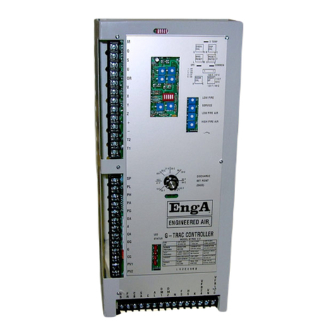
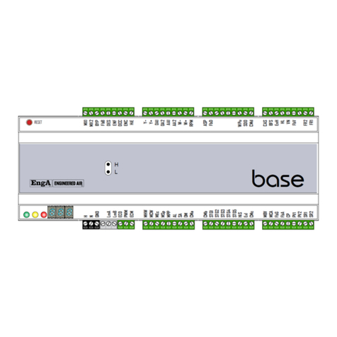
Engineered air EngA W-TRAC User manual

IOM‐49 Mar99R4
INSTALLATION, OPERATION
AND MAINTENANCE MANUAL
FOR
W-TRAC
HEAT WHEEL CONTROLLER
UNIT MODEL NO. _________________
UNIT SERIAL NO. _________________
SERVICED BY: ___________________
TEL. NO: ________________________
CANADIAN
HEAD OFFICE
AND FACTORY
USA
HEAD OFFICE
AND FACTORY
CANADIAN
EASTERN FACTORY
1401 HASTINGS CRES.
SE
CALGARY, ALBERTA
T2G 4C8
Ph: (403) 287-4774
Fx: 888-364-2727
32050 W. 83r
d
STREET
DESOTO, KANSAS
66018
Ph: (913) 583-3181
Fx: (913) 583-1406
1175 TWINNEY DRIVE
NEWMARKET,
ONTARIO
L3Y 5V7
Ph: (905) 898-1114
Fx: (905) 898-7244
SALES OFFICES ACROSS CANADA AND USA
Retain instructions with unit and maintain in a legible condition.
Please give model number and serial number when contacting
Engineered Air for information and/or parts.
www.engineeredair.com

A
IOM‐49 2of12 Mar99R4
W‐TRAC
IfanyerrorsoromissionsarenotedpleasecontactthenearestEngineeredAirTechnicalService
Department.
Toensurewarrantyishonored,onlyqualifiedpersonnelshouldbeemployedforserviceand
troubleshooting.IffurtherinformationisrequiredpleasecontactthenearestEngineeredAiroffice.
Therearetwosetsofelectricaldrawingandunitfunctionsheetsprovidedwiththeappliance.Onesetisin
anenvelopewhichalsocontainstheOperation,InstallationandMaintenancemanual(s).Thispackageis
forcopying,thenshouldeitherbereturnedtotheapplianceorstoredinasafeplace.Theothersetis
attachedtothecontrolpaneldoorandshouldneverberemoved.
Pleasereportanyomissionstothenationalservicemanager.
Warning:
Improperinstallation,adjustment,alteration,serviceormaintenancecancause
propertydamage,injuryordeath.Readtheinstallation,operatingand
maintenanceinstructionsthoroughlybeforeinstallingorservicingthisequipment.
Warning: Thisunitisconnectedtohighvoltages.Electricalshockordeathcouldoccurif
instructionsarenotfollowed.Thisequipmentcontainsmovingpartsthatcanstart
unexpectedly.Injuryordeathcouldoccurifinstructionsarenotfollowed.All
workshouldbeperformedbyaqualifiedtechnician.Alwaysdisconnectandlock
outpowerbeforeservicing.DONOTbypassanyinterlockorsafetyswitchesunder
anycircumstances.

AW-TRAC
IOM‐49 3of12 Mar99R4

AW-TRAC
IOM‐49 4of12 Mar99R4
TableofContents
INTRODUCTION..................................................................................................................................................5
CONTROLLERRATINGS......................................................................................................................................5
CONTROLLERDESCRIPTION...............................................................................................................................6
TERMINALLIST...................................................................................................................................................6
DIPSWITCHES....................................................................................................................................................6
INDICATIONANDDIAGNOSTICLIGHTS..............................................................................................................7
ADJUSTMENTPOTS............................................................................................................................................7
TEMPERATURECONTROL..................................................................................................................................7
BASESETPOINT..................................................................................................................................................8
SETPOINTRESET.................................................................................................................................................8
FROSTCONTROL................................................................................................................................................8
EXHAUSTAIRRH%SENSOR...............................................................................................................................8
RETURNAIRRH%SENSOR.................................................................................................................................9
BDRHPREDICTEDRETURNAIRRELATIVEHUMIDITY........................................................................................9
WIRING...............................................................................................................................................................9
SENSORTABLE.................................................................................................................................................12
SERVICENOTES................................................................................................................................................10
ROTATION........................................................................................................................................................10
MOTORSPEEDCONTROL.................................................................................................................................10
KBVF/SIVF(R)..................................................................................................................................................10
WHEELROTATIONSPEED................................................................................................................................11
SENSORCALIBRATION.....................................................................................................................................11
DISCHARGETEMPERATURECALIBRATION......................................................................................................11
EXHAUSTTEMPERATURECALIBRATION..........................................................................................................11
HUMIDITYSENSORS.........................................................................................................................................12

AW-TRAC
IOM‐49 5of12 Mar99R4
INTRODUCTION
TheW‐TRACisasupervisorycontrollerforEngineeredAirHRWheatwheels,withbuiltindischargeair
temperaturecontrolandoptionalexhaustfrostcontrol.
Theinformationusedinthismanualshouldbeusedinconjunctionwiththeunitfunctionsheet(s)andthe
HRWseriesInstallation,Operation,andMaintenancemanual.
TheW‐TRACisdesignedtocontrolonlyEngineeredAirequipment.Variousupgradesandimprovements
havebeenmadeovertime.Alwaysincludeanysuffixlettersandnumbersfortroubleshootingand/or
replacement.AllW‐TRACmodelsarebackwardscompatible;howeversomeadditionalwiringmaybe
required.
Note:Itisnecessarythatalloftheremotewiringandcontrolsbecompleteandoperationalbeforestarting
theappliance.
CONTROLLERRATINGS
Powerrequirements:24VAC,40VA.
ContactRating:120V3Ainductive
0‐10Vdcinputimpedance:5k
Environment:‐40to120°F(‐40to50°C)non‐condensing.

AW-TRAC
IOM‐49 6of12 Mar99R4
CONTROLLERDESCRIPTION
TERMINALLIST
Terminal Description
C1 Sensorcommon,and0‐10Vdcresetcommon(‐).
S 0‐10Vdctemperatureresetinput(+).
D Supplyairtemperaturesensorinput.
E Exhaustairtemperaturesensorinput.
A Outsideairtemperaturesensorinput.
RMH 0‐10VdcreturnairRH%input.
EXH 0‐10VdcexhaustairRH%input.
MOD 0‐10Vdcheatwheelcontroloutput(+).
C2 0‐10Vdcheatwheelcontroloutput(‐).
+12 12Vdcoutputpower
+32 32Vdcoutputpower(RH%sensorhot)
T2(N) 24VacNeutralpowerinput.
T1 24VacHotpowerinput.
6 Outputcontactcommon
5 Outputcontactnormallyclosed(N.C.)
4 Outputcontactnormallyopen(N.O.).Startcontact.
P1 Lowoutputpotentiometer(legacy,foroldstyleDCdrivemotors).
P2 Wiperoutputpotentiometer(legacy,foroldstyleDCdrivemotors).
P3 Highoutputpotentiometer(legacy,foroldstyleDCdrivemotors).
DIPSWITCHES
W‐TRACconfigurationoptionsareconfiguredbyDIPswitchselection and/or wiring connections. These
arefactorysetandshouldnotnormallyneedtobealtered.
DIPSW Description
BDRHSPEN ‘ON’whenRH%sensingofthereturnairisnotused.W‐TRACwillcontrolbasedon
pre‐definedRH%values.Switchwillbe‘OFF’whensensingactualRH%.
EXRHCTRL ‘ON’whenusingexhaustairRH%sensing.
BDRHCTRL ‘ON’whenRH%sensingofthereturnairisnotused.Switchmustbeinthesame
positionasBDRHSPEN(above).
MANHISPEED* ‘ON’todrivetheoutputtomaximumwheelrotationspeed.
MANLOSPEED* ‘ON’todrivetheoutputtominimumwheelrotationspeed.
*Donotenablebothswitchesatthesametime,orleaveeitherswitch‘on’innormaloperation.

AW-TRAC
IOM‐49 7of12 Mar99R4
INDICATIONANDDIAGNOSTICLIGHTS
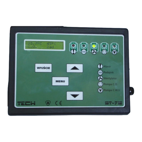
OnthefaceoftheW‐TRACare5redLEDindicationlights.
Light Description
LowExhaust
Temp
Indicatestheexhausttemperatureisbelowthecalculatedminimumallowable
temperature,whichisbasedontheamountofmoistureinthereturnair(measured
orestimated)andtheambienttemperature.
BadSensor Shortedoropensensorindication.
VentMode Wheelwillbestopped.Nocallforheatingorcooling.
DischargeTooHot Wheelisslowingdownduetoexcessiverecoveryofheat.
FrostMode Heatwheelrotationspeedisreducingtopreventfrostaccumulation.
ADJUSTMENTPOTS
Thereareanumberofsettingandcalibrationpotentiometers(POT’s)locatedonthefaceoftheW‐TRAC.
Modificationstotheseshouldonlybedonebyexperiencedandqualifiedpersonnel.
POT Description
DISCAL Dischargetemperaturesensorcalibration.
EXCAL Exhausttemperaturesensorcalibration.
AMBCAL Ambient/outdoortemperaturesensorcalibration.
BDRH PredicteddesignreturnairRH%scale(1‐4).
TEMPERATURECONTROL
TheW‐TRAChas4modesofoperation;Heat,Defrost,VentandCool,thatcontrolsthewheelrotational
speedtoachievethedesiredtemperaturesetpointofsupplyairleavingthewheel.
Whentheoutsideairiscolderthantheexhaustair,theheatwheelwillrotatetocaptureheatfromthe
exhaustairsideandtransferittothesupplyairstream.Increasingtherotationspeedwillincreasethe
amountofheattransferred.
Iftoomuchheatisbeingremovedfromtheexhaustairstreamitispossibleforfrosttoaccumulateonthe
faceoftheheatwheel.TheW‐TRACwillautomaticallyreducetherotationspeedtopreventfrosting.
Ifnoheatingisrequired,theW‐TRACwillstopthewheelrotationandenter‘ventmode’.

AW-TRAC
IOM‐49 8of12 Mar99R4
IftheoutsideairtemperatureiswarmerthantheexhaustairtheW‐TRACwillenter‘coolmode’and
rotatetheheatwheeltotransferheatfromtheoutsideairtotheexhaust.
BASESETPOINT
TheW‐TRACisdesignedtobeadischargeairtemperaturecontroller.Thebasedischargeairtemperature
issetfromthesetpointcontrolknoblocatedonthefaceoftheW‐TRAC.
SETPOINTRESET
Thebasedischargeairtemperatureisoftenmodifiedfromaremotesignaltomaintainthedesired
temperatureofthesuppliedspace.Thisiscalledreset.TheW‐TRACdischargetemperaturecanbereset
fromavarietyofsourcesusinga0‐10VDCsignal.
AnoffsettotheBMSinputrangecanbeimplementedbyaddinga7.5kresistorinserieswithterminalS.
Thefollowingtabledescribesthechangeofdischargesetpointfromtheinputvoltage(toterminalsS+and
C1‐),withasetpointfixedat66°F.Refertotheequipmentfunctionpageforthedesignresetrange.
InputVoltage
0.0 2.0 4.0 6.0 8.0 10.0
Discharge
Setpoint(°F/°C)
NoResistor 30/‐1 40/4 45/7 52/11 60/15 66/19
7.5kResistor 48/9 53/12 56/13 59/15 63/17 66/19
FROSTCONTROL
Frostshouldnotbeallowedtobuilduponthewheel.Itisnecessarytoreducetheamountofheat
recoveredwhentheoutsidetemperatureisbelowthefreezingpoint(0°C/32°F)andtheexhaustleaving
temperaturefallstoapointthatfrostcanbegintoform.Frostmaydamagethewheelandreduceairflow.
Operatingtheheatwheelclosetothefrostthresholdtemperaturewillprovidemaximumenergyrecovery.
Thereare3differentmethodsofprovidingfrostcontrol,allofwhichreducetheheatwheelrotation
speed.
EXHAUSTAIRRH%SENSOR
ThismethodofcontrolrequiresahumiditysensorconnectedacrossterminalsEXHandC2.DIP1and3
mustbeOFF,DIP2mustbeON.Thesensorisinstalledintheexhaustairsection,justaftertheheat
wheel.

AW-TRAC
IOM‐49 9of12 Mar99R4
Whentheoutdoorambienttemperatureisbelow15°F(‐10°C)thespeedoftheheatwheelwillbereduced
tomaintaintheleavingexhaustairhumiditybetween80–90%.Thisapplicationrequireshighaccuracy
humiditysensors.
RETURNAIRRH%SENSOR
ThismethodoffrostcontrolrequiresaRHsensorinstalledintheequipmentreturnairsection,justbefore
theheatwheel,wiredintoterminalsRMHandC2.DIP3mustbeON,DIP1and2mustbeOFF.
UsingthevaluesoftheRHandambient(outsideair)sensor,theW‐TRACcalculatestheminimum
allowableexhaustairtemperaturethatwillkeepfrostfromformingonthewheel.
BDRHPREDICTEDRETURNAIRRELATIVEHUMIDITY
RH%sensingisnotusedinthismethodoffrostcontrol.DIP1and3mustbeON,whileDIP2isOFF.
TheW‐TRACmayoperatewithouttheuseofhumiditysensinginsituationswheretheRH%valuesare
expectedtobereasonablyconstant.Inthesecases,theW‐TRACoperatesbysensibletemperatureonly.
Whenenabled,theBDRHpot(BuildingDesignRelativeHumidity)issetaccordingtotheexpecteddesign
returnairconditions.RefertothetablebelowtosettheexpectedvaluesbasedontemperatureandRH%.
Table1
BDRHsetting ReturnAirConditions
70°F(21°C) 75°F(24°C) 80°F(27°C)
1 <25% <21% <18%
2 26–32% 22–27% 19–23%
3 33–39% 28–33% 24–27%
4 40–49% 34–42% 28–35%
Tousethistable,firstselectthereturnairtemperature,thenselecttheRH%rangeinthecolumnbelow,
thenselecttheBDRHsettingtotheleft.
WIRING
TheW‐TRACterminalsHandNrequireaminimum24VAC,40VAclass2powersupplythatdoesnotneed
tobeisolatedfromtherestofthesystemscomponents.
TerminalNshouldbewiredtothecommonofthesamesourcesupplyingpowertoterminalsE,A,andK.
Allremotewiringshouldbeinstalledinaclean(noelectricalnoise)environment.Wiresizeshouldbea
minimumof24ga.twistedpairtoreduceelectricalnoise(shieldedwireisrecommended).Forlongerruns

AW-TRAC
IOM‐49 10of12 Mar99R4
(over50ft.eq.length),theuseofaminimum20gauge‐shieldedwireisrecommended.Theshieldshould
begroundedatthecontrollerendonly,withtheotherendtaped.
Itisimportanttoensurecorrectpolaritywhenwiringintothesystem.
NOTE:Fieldanalogcontrolinputsrequiresignalisolationtopreventgroundloop
signalcorruptionand/ordamagetothecontroller(s).
SERVICENOTES
ROTATION
Mostheatwheelshaveapurgesectiontopurgeexhaustairtrappedinthewheelflutesbeforetheyrotate
tothesupplyairside.Thecorrectwheelrotationdirectionisnotedonthefaceoftheheatwheel.Drive
motorrotationmaybechangedatthemotorwireconnectionsorontheinverterdrivefeedingthemotor
(ifused).
MOTORSPEEDCONTROL
Themodulating0‐10Vdcmotorspeedoutputmaybeconnectedtoavarietyofcontrollersand/or
inverters.Refertotheequipmentwiringdiagramforconnectiondetails.Thefollowingsetupparameters
aretypical.Alwaysrefertotheequipmentfunctionsheetforanychanges.Toensurepropersetup
operation,donothaveDIP4andDIP5onatthesametime.
KBVF/SIVF(R)
TheKBVFinverterdriveandSIVFsignalisolatoraremanufacturedbyKBElectronicsInc.Theinverterand
isolatorinstallationandoperationmanualsareincludedintheinformationpackage,originallylocatedin
themainequipmentelectricalpanel.The0‐10VdcW‐TRACcontroloutputfeedsintotheSIVFsignal
isolatorwhich,inturn,feedsanisolated0‐5VdcsignaltotheKBVFinverterdrive.
HighSpeed
TurnonW‐TRACDIP4toforcetheW‐TRACtomaximumoutput(near10Vdc).Notethatifthe
W‐TRACisoperatinginfrostmodeDIP4willnotallowthedrivetogotofullspeed.Measurethemotor
ampsandconfirmthereadingsarelessthanthemaximummotorampacity.Ifpossible,measureand
confirmtheoutputfrequencyis60Hz.
TheKBVFisfactorysetto100%ofratedfrequency(60Hz)andshouldnotbeadjusted.

AW-TRAC
IOM‐49 11of12 Mar99R4
LowSpeed
TurnonDIP5todrivetheoutputtominimum(0Vdc).AdjusttheminimumspeedpotontheKBVF
inverterdriveuntiltheheatwheeljustbeginstoturn,usuallybetween0.5and2rpm.Turnthepoweroff,
andthenrestartthesystemtoconfirmthemotorhasenoughstartingtorquetoreliablystartrotatingthe
heatwheel.
ReturnallDIPswitchestotheiroriginalposition.
WHEELROTATIONSPEED
Maximumwheelrotationspeedwillbefactorysetintherangeof30‐40rpm,at60Hz,dependingonthe
sizeoftheheatwheel.
Minimumwheelspeedisdependentonthestartingtorqueofthemotorandheatwheel,usuallybetween
0.5and2rpm.
SENSORCALIBRATION
DischargeTemperatureCalibration
Removethesupplyairtemperaturesensorandmeasureboththesensorresistanceandthetemperature
atthesensingelement.Comparethesereadingstothesensortablevalues.Iftheresistanceisoutby
morethan16ohms,replacethesensor.
Measuringasensortemperaturebetween60–70°F,slowlyrotatethetemperaturesetpointdial
counterclockwiseuntilthe‘DischargeTooHot’lightjustcomeson.
Slowlyincreasethetemperaturesetpointdialuntilthelightgoesoff.
Thesetpointshouldmatchthesensedtemperaturemeasurement.Ifnot,adjustthecalibrationpot
andrepeattest.
ExhaustTemperatureCalibration
Removetheexhaustairtemperaturesensorandmeasureboththesensorresistanceandthetemperature
atthesensingelement.Comparethesereadingstothesensortablevalues.Iftheresistanceisoutby
morethan16ohms,replacethesensor.The‘badsensor’LEDmayturnonandoffduringthisprocedure.
PlaceajumperwireacrossterminalsAandC1.
Removetheexhausttemperaturesensorandreplacewitha909Ωresistor.
NotethepositionoftheBDRHpot,andthenadjusttoposition2.

AW-TRAC
IOM‐49 12of12 Mar99R4
Slowlyrotatepot#2counterclockwise(EXCAL))untilthelowexhausttemperaturelightcomeson.
Slowlyrotatepot#2clockwiseuntilthelowexhausttemperaturelightjustturnsoff.
ReconnectallsensorsandsetpotBDRHbacktoitsoriginalposition.
Humiditysensors
AccuratelymeasuretherelativehumidityatthesensorlocationandcomparetothesensorVdcoutput.
The0‐10Vdcoutputisproportionalto0‐100%RH.
SENSORTABLE
SensorResistanceChartforTE6000EA3
Table2
°C °F Resistance°C °F Resistance°C °F Resistance
‐40 ‐40 602 18.3 65 983 48.9 120 1234
‐34.4 ‐30 633 20 68 996 54.4 130 1269
‐28.9 ‐20 665 20.6 69 1000.7 60 140 1333
‐23.3 ‐10 698 21.1 70 1005 65.5 150 1365
‐17.8 0 732 23.9 75 1026.5 71.1 160 1437
‐12.2 10 768 26.7 80 1048 76.7 170 1491
‐8.7 20 804 29.4 85 1070 82.2 180 1546
‐1.1 30 842 32.2 90 1092 87.7 190 1602
4.4 40 881 35.6 95 1116 93.3 200 1659
10 50 921 37.8 100 1139 98.8 210 1718
12.8 55 942 43.3 110 1186 100 212 1778
Referenceresistanceis1035ohmsat77°F.Resistancetolerancesare±0.05to0.15%at77°F.Temperature
range+32to+104°F.
Table of contents
Other Engineered air Controllers manuals
Popular Controllers manuals by other brands
Siemens
Siemens RVD230 Basic documentation
Joy-it
Joy-it LINKERKIT OLED manual
Afag
Afag IRG 1-MS Translation of original operating instructions
Emerson
Emerson Dixell XR70CHC Installing and operating instructions
dixell
dixell XC660D Installing and operating instructions
Asco
Asco Froment SIGMA IHT Version 4 quick start guide
