Engineering Incorporated PMA9000EX User manual

202-920-0100 Page 1MAR. 2008 PMA9000EX Pilot Guide
This product is intended for Experimental Aircraft only.
Covered under one or more of the following Patent No.
4,941,187, 5,903,227, 6,160,496, 6,493,450
9800 Martel Road
Lenoir City, TN 37772
www.ps-engineering.com
PMA9000EX
PMA9000EX
Audio Selector Panel
Marker Beacon Receiver
High-fidelity Stereo Intercom System
with Bluetooth Phone interface & MP3 player
Pilot’s Guide
Pilot’s Guide
and
and
Operation Manual
Operation Manual
202-920-0100 Revision 3 March 2008
Page 2 202-920-0100 PMA9000EX Pilot Guide
This pilot guide provides detailed operating instructions for the PS
Engineering PMA9000EX, Audio Selector Panel/Intercom Systems.
Please read it carefully before using the equipment so that you can
take full advantage of its capabilities.
This publication covers the basic operating areas of the PMA9000EX
systems. They are: Com Transceiver Selection, Receive Audio Selec-
tor, Intercom, Marker Beacon Receiver, Music, Front Panel Utility
Jack and Telephone.
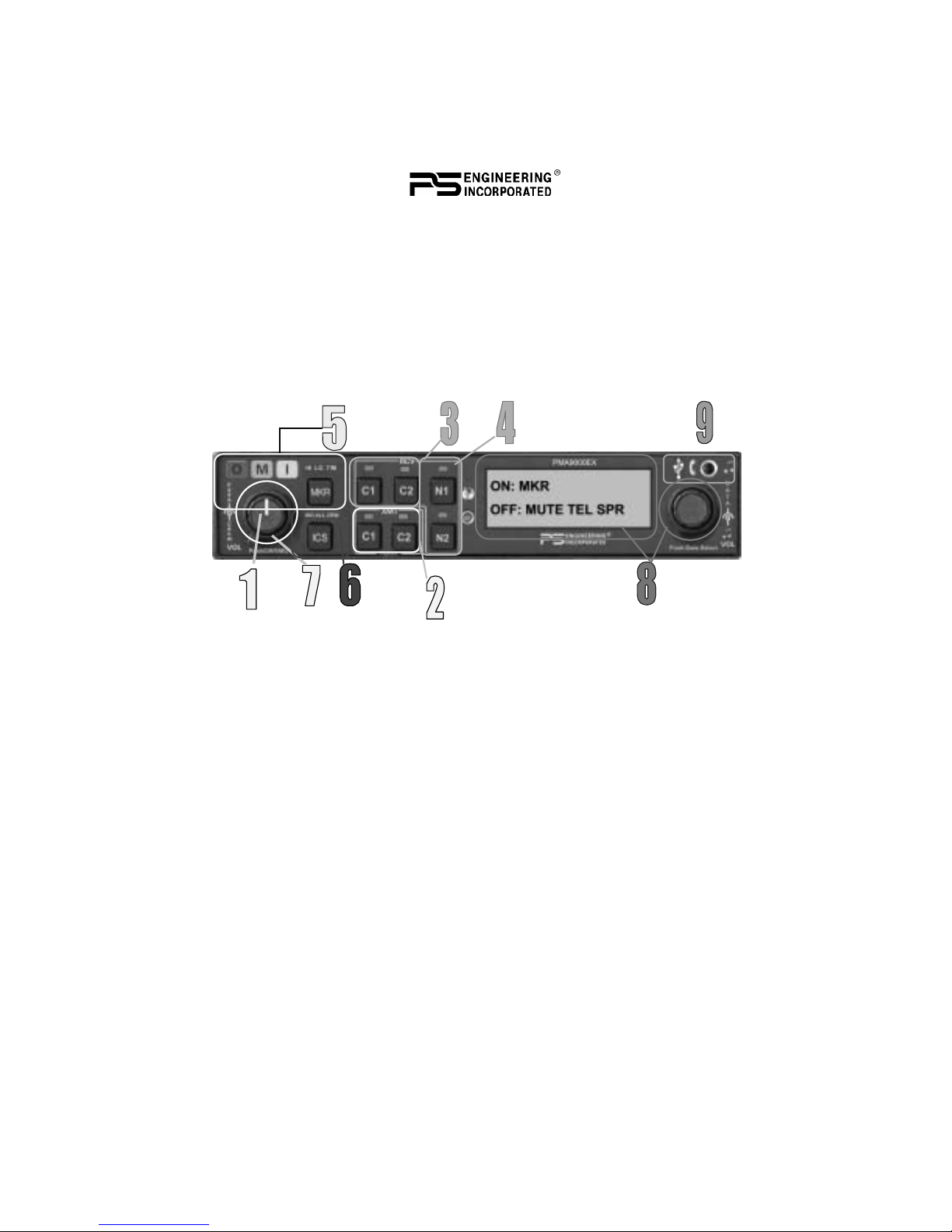
PMA9000EX Controls
1.0 Audio Selector Panel
1.1 Power and Fail-Safe (1)
Unit power is turned on and off by pushing the volume knob. In the
OFF or "EMG" fail-safe position, the pilot headset is connected di-
rectly to Com 1 as well as unswitched input #1. This allows commu-
nication capability regardless of unit condition. Any time power is
removed or turned OFF, the audio selector will revert to fail-safe
mode.
The power switch controls all audio selector panel functions, inter-
com and marker beacon receiver. All pushbutton selections and menu
modes will be remembered and return to the last state when turned on.
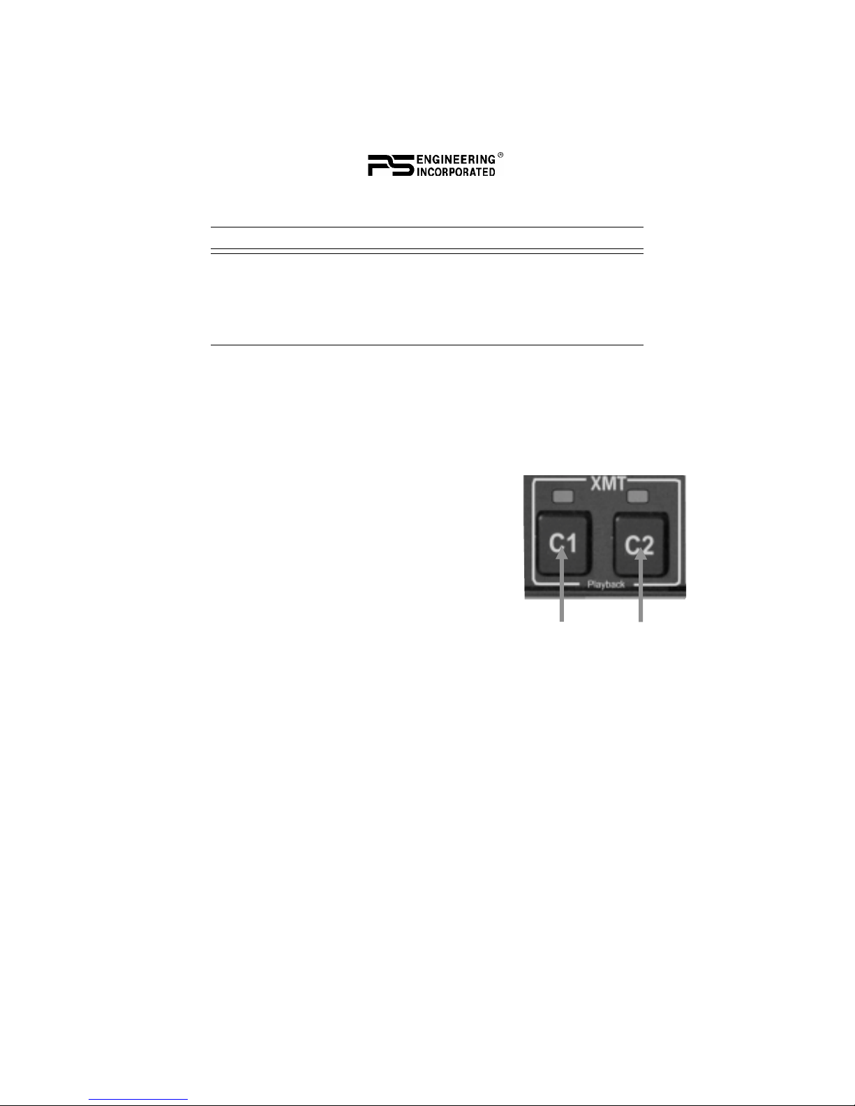
1.1 Communications Transmit (XMT) Selection (2)
The two buttons C1 and C2, (# 2) in the XMT section control which

202-920-0100 Page 3MAR. 2008 PMA9000EX Pilot Guide
communications radio is selected for transmit-
ting. Push the lower button to select the de-
sired COM transmitter. A green LED above
the button illuminates to indicate that the au-
dio is selected. The top row of RCV pushbut-
tons (# 3) allows selection of the receiver au-
dio.
The PMA9000EX-Series has an automatic com receiver selector sys-
tem. Audio from the selected transceiver is automatically heard in the
headsets and speaker (if selected). You can check this function by
switching from COM 1 transmitter to Com 2 transmitter by pressing
the COM 2 transmitter selector pushbutton. See that the associated
Com 2 receive pushbutton indicator light that is located immediately
above the Com 2 transmitter pushbutton turns green. This guarantees
that the pilot will always hear the audio from the transceiver selected
for transmit.
The PMA9000EX “remembers” the receiver selection, so that when
switching transmitters from COM 1 to COM 2, if COM 2 audio was
previously selected, COM 1 audio will continue to be heard. This
eliminates the pilot having to switch Com 1 audio back on, after
changing transmitters.
When switching from COM 1 to COM 2 while Com 2 was not previ-
ously selected, COM 1 audio will be switched off. In essence, switch-
ing the mic selector will not override prior selection of COM receiver
audio.
In normal (not split) modes, the PMA9000EX gives priority to the
pilot’s radio Push-To-Talk (PTT). If the copilot it transmitting, and
the pilot presses his PTT, the pilot’s microphone will be heard over
the selected com transmitter.
1.1.1.1 Split Mode
The split mode can be activated at any time by pressing the C1 and
C2 XMT buttons at the same time. This places the pilot on COM 1
and the Copilot on COM 2. All four COM indicators will illuminate to
indicate that the panel is in split mode.
In split mode, the intercom will remain active in the selected mode,
however, and music will be muted in the crew positions.
Pilot on COM 2 and Copilot on COM 1 is not possible.
Split Mode does not turn off Nav, ADF, or Aux selected audio to
Page 4 202-920-0100 PMA9000EX Pilot Guide
pilot. However, the copilot will only hear the copilot-selected com
receiver and unswitched inputs
NOTE
Due to the nature of VHF communications signals, and the size
constraints in general aviation aircraft, it is probable that there will be
some bleed-over in the Split mode, particularly on adjacent
frequencies. PS Engineering makes no warranty about the suitability
of Split Mode in all aircraft conditions.
1.1.1.2 Swap Mode (Switch from Com 1 to Com 2 remotely)
With a yoke mounted, normally open momentary switch, the pilot can
change from the current Com transceiver to the other by depressing
this switch. To cancel "Swap Mode," the pilot may either press the
yoke mounted switch again, or select a different Com with the XMT
buttons.
1.1.1.3 Internal Recorder
The PMA9000EX comes equipped with an inter-
nal recorder. This digital system stores the last
incoming audio from the radio you have selected
for transmit. It can store up to 60 seconds of au-
dio. The pilot and copilot hear the playback..
Because of the continuous nature of AWOS re-
cordings, these will not trigger the recorder cir-
cuits.
1.1.1.3.1 Playback
Recording is automatic. To play back the message, press and hold the
XMT button for the communications radio that is selected for trans-
mit for about 1 second or until the message plays back.
To stop the, hold the same button until the playback stops, about 2
seconds. Then the next 1-second press will play the next earlier mes-
sage stored.
The playback will stop automatically when the selected com audio
becomes active again. Press the button again to start the message
again. The audio received during playback is NOT stored.
202-920-0100 Page 5MAR. 2008 PMA9000EX Pilot Guide
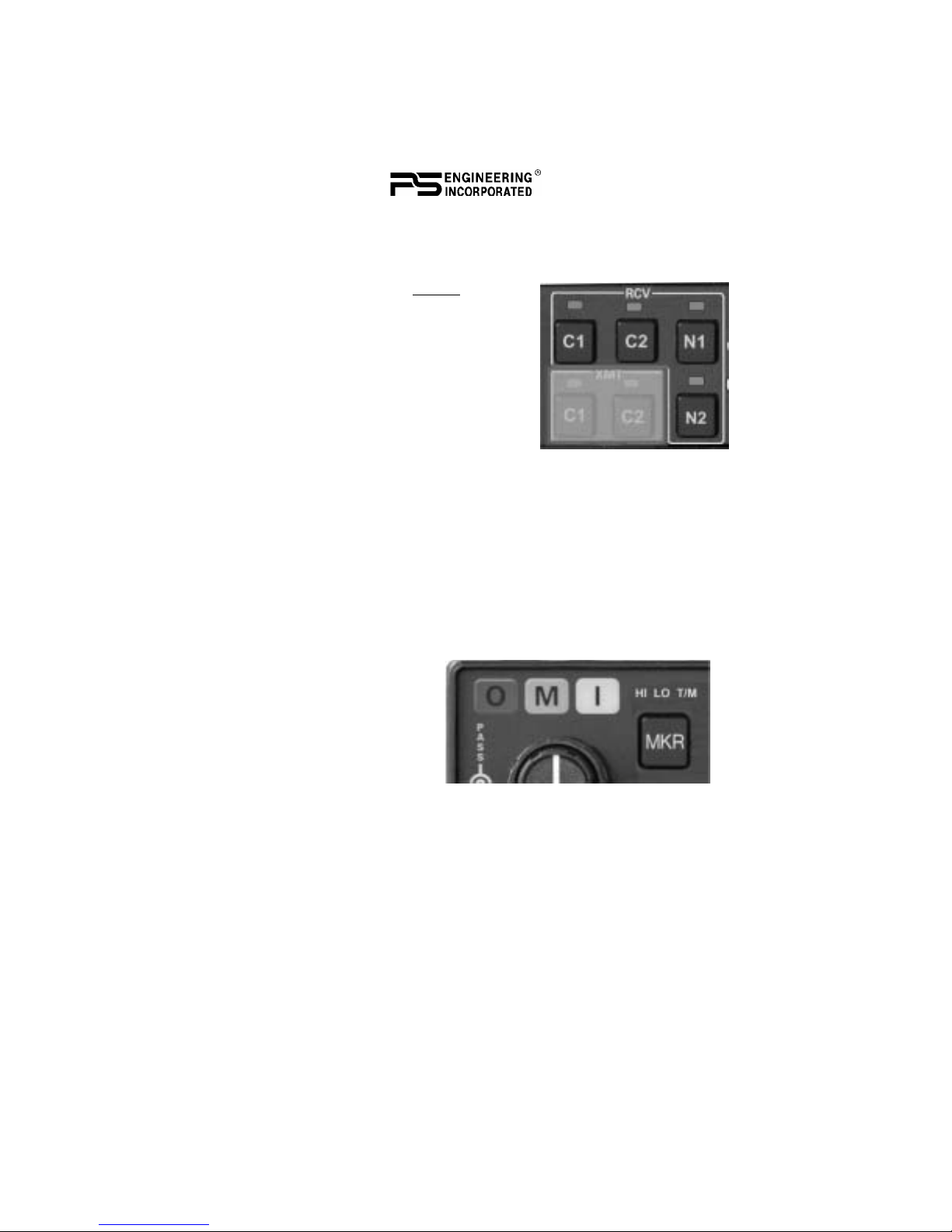
1.2 COM Audio Receive Selector (3)
Communication audio from the other radio, not selected for transmit,
can be heard by pressing the associated
RCV button. You will always hear the
audio from the selected transceiver.
1.3 NAV Audio selection (4)
VHF Navigation receiver audio is selected
through two momentary, push-button,
backlit switches. VHF Navigation aid au-
dio push buttons are labeled N1, N2.
The users can identify which receivers are
selected by noting which green LEDs are lit above the button.
2.0 Marker Beacon Receiver (5)
2.1 Marker Beacon Operation (5)
The Marker Beacon Receiver uses visual and audio indicators to alert
you when the aircraft passes over a 75 MHz transmitter.
The Blue lamp, labeled “O”, is the Outer Marker lamp and has an
associated 400-Hertz 'dash'
tone. The lamp and tone will
be keyed at a rate of two
tones/flashes per second
when the aircraft is in the
range of the Outer Marker
Beacon.
The Amber lamp, labeled
“M”, is the Middle Marker lamp and is coupled with a 1300 Hertz
tone. It is keyed alternately with short 'dot' and long 'dash' bursts at 95
combinations per minute.
The White lamp, labeled “I”, is the Inner marker and has a 3000 Hertz
'dot' tone. The lamp and tone will be keyed at a rate of six times per
second.
The MKR button controls audio selection, marker sensitivity, and
audio muting, and lamp test.
• MKR button press of < 1 second: toggles between high
and low receiver sense

Page 6 202-920-0100 PMA9000EX Pilot Guide
• MKR button press between 1 and 2 seconds: Activates
audio mute, and marker lamp test activated. The next bea-
con received will re-activate the audio.
• MKR button press > 2 seconds: toggle marker audio on/
off. When the audio is selected, MKR will appear in the
display. Marker audio can also be controlled using the
same manner as Secondary Navaid Selection
Use "HI" sensitivity initially. This allows you to hear the outer
marker beacon about a mile out. Then touch the smaller MKR button
to switch into Low Sensitivity mode. “LO” sensitivity gives you a
more accurate location of the Outer Marker.
Holding the MKR button for two seconds activates marker test lamp,
which illuminates all three lamps simultaneously to assure the lamps
(internal and external) are in working order. Releasing the button re-
turns to the last sensitivity. The marker audio level is preset at the
factory, and a service adjustment is available if necessary.
3.0 Intercom (6)
3.1 IntelliVox® VOX-Squelch
No adjustment of the IntelliVox® squelch control is necessary. There
is no field adjustment. Through three individual signal processors, the
ambient noise appearing in all six microphones is constantly being
sampled. Non-voice signals are blocked. When someone speaks, only
their microphone circuit opens, placing their voice on the intercom.
The system is designed to block continuous tones, therefore people
humming or whistling in monotone may be blocked after a few mo-
ments.
For consistent performance, any headset microphone must be placed
within ¼-inch of your lips, preferably against them. (ref: RTCA/DO-
214, 1.3.1.1 (a)). It is important to have the microphone element par-
allel to your mouth, and not twisted inside the cover.
It is also a good idea to keep the microphone out of a direct wind
path. Moving your head through a vent air stream may cause the In-
telliVox® to open momentarily. This is normal.
The IntelliVox® is designed to work with normal aircraft cabin noise
levels (70 dB and above). Therefore, it may not always recognize
speech and clip syllables in a quiet cabin, such as in the hangar, or
without the engine running. This is also normal.

202-920-0100 Page 7MAR. 2008 PMA9000EX Pilot Guide
3.2 Intercom Modes
The “ICS” pushbutton switch on the left side of
the PMA9000EX provides the selection of the
three intercom modes.
This button cycles through the intercom modes,
from left to right and then back, ISO, ALL, CRW
(Crew), ALL, and ISO. The illuminated text
shows the active mode .
ISO:The pilot is isolated from the intercom and is
connected only to the aircraft radio system. He will hear the aircraft
radio reception (and sidetone during radio transmissions). The copilot
and passengers will hear the music sources as configured by the audio
panel.
ALL:All parties will hear the aircraft radio and intercom. Crew will
hear Entertainment 1, passengers can hear Entertainment 1 or 2. Dur-
ing any radio or intercom communications, the music volume auto-
matically decreases. The music volume increases gradually back to
Headset
Manufacturer Model Part Number
Bose Dynamic
Electret
M87
90010
90015
90020
David Clark H10-30
H10-20, H10-40
H10-13.4, 13X
H20-10X
90010
90015
90015
90015
Lightspeed All 90015
Peltor 7003
ANR Pro, 7000 90010
90015
Pilot 11-20, 11-90, 1776, DXL 90015
Sennheiser All 90015
Telex Airman 750, AIR4000
AIR3000, Echelon 100 90010
90015
Oregon Aero MicMuff Part Numbers
Note: For optimum microphone performance, we recommend use of a
Microphone Muff Kit from Oregon Aero (1-800-888-6910). This will not only
optimize VOX performance, but will improve the overall clarity of all your
communications.
Page 8 202-920-0100 PMA9000EX Pilot Guide
nthe original level after communications have been completed. An
Alternate Intercom Function is available that prevents the passengers
from hearing aircraft radios in ALL mode. See Section XX.X for de-
tails.
CREW: Pilot and copilot are connected on one intercom channel and
have exclusive access to the aircraft radios. Again, the music that the
crew and passengers will hear is controlled in the music distribution
setup.
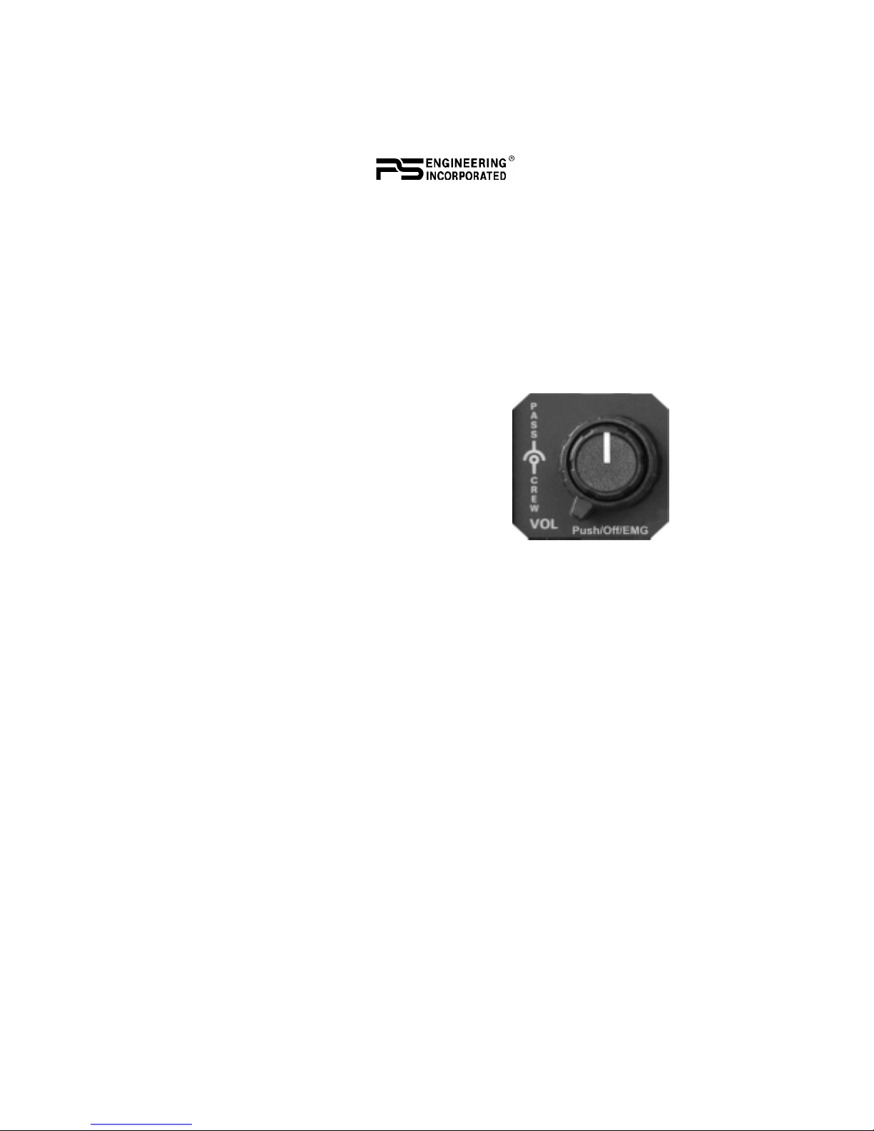
3.3 Intercom Volume Control (7)
The small volume control knob adjusts the
loudness of the intercom for the pilot and
copilot. It has no effect on selected radio lev-
els, music input levels or passengers' volume
level.
The larger, outer volume control knob con-
trols intercom volume or the passengers. It
has no effect on radio or music levels.
Adjust the radios and intercom volume for a
comfortable listening level. Most general
aviation headsets today have built-in volume controls; therefore, vol-
ume also can be further adjusted at the individual headset.
3.1.3.1 Mono Headsets in Stereo Installation
The pilot and copilot positions work with stereo or mono headsets.
All passenger headsets are connected in parallel. Therefore, if a mon-
aural headset is plugged in to a PMA9000EX Stereo installation, one
channel will be shorted. Although no damage to the unit will occur,
all passengers will lose one channel, unless they switch to the
“MONO” mode on the headset.
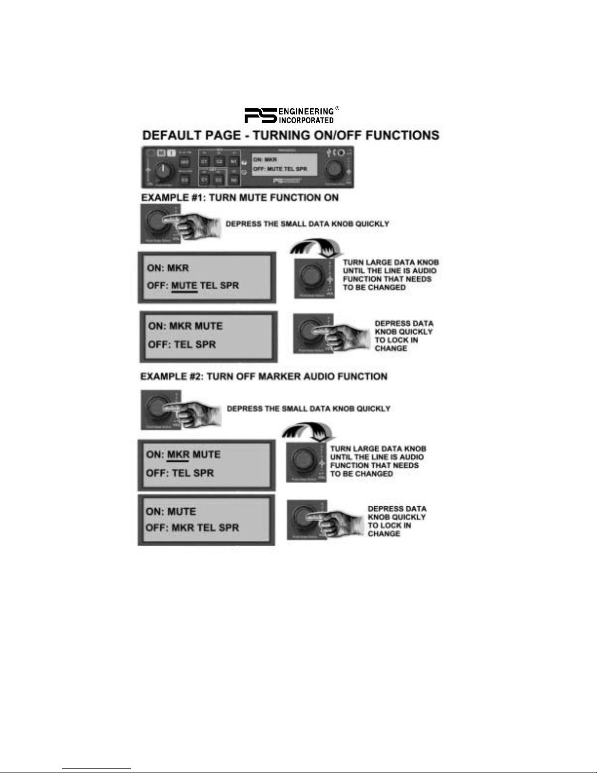
4.0 EnCoder And Push Switch interface (ECAPS) (8)
ECAPS is a system that consists of two encoding data knobs and a
push-push switched integral into the small data knob. These control
the menu, submenus, and selection of items for control.
The primary menu contains frequently accessed items: SPR (cockpit
Speaker), TEL (telephone) MKR (Marker audio), and MUTE (music
mute control).
Pressing the small knob for two (2) seconds will activate the sub
menus. Submenus contain: ADF, DME and AUX audio, MP3 and
202-920-0100 Page 9MAR. 2008 PMA9000EX Pilot Guide
other music selections and controls, Alternate Intercom mode control,
Public Address, and LCD display controls.
Turn the large data knob to view the sub menus. Turn the small knob
to toggle selections on or off, or adjust levels.

Page 10 202-920-0100 PMA9000EX Pilot Guide
Pushing the small data knob will activate the option, and exit the
menu, or, the option will be selected automatically after five (5) sec-
onds.
The menu function will always come up on the display with last used
function first.
4.1 Cockpit Speaker
The speaker (SPR) can be turned on or off in the same manner as the
MKR from the primary menu. This control will place all selected au-
dio on the cockpit speaker when this switch is selected. Except for the
unswitched audio, the speaker amplifier is not active in the "Split
Mode”.
Unswitched audio, (the inputs dedicated to autopilot disconnect, al-
timeter warning, etc.) will come through the speaker regardless of the
speaker button position.
Depending on installation, important audio annunciations such as ra-
dar altimeter or autopilot disconnect will come over the speaker even
if it is not selected, while other unswitched, but muted inputs, such as
GPS alerts, will only be present if the SPR button is selected. Consult
your professional avionics installer for these important configuration
details.
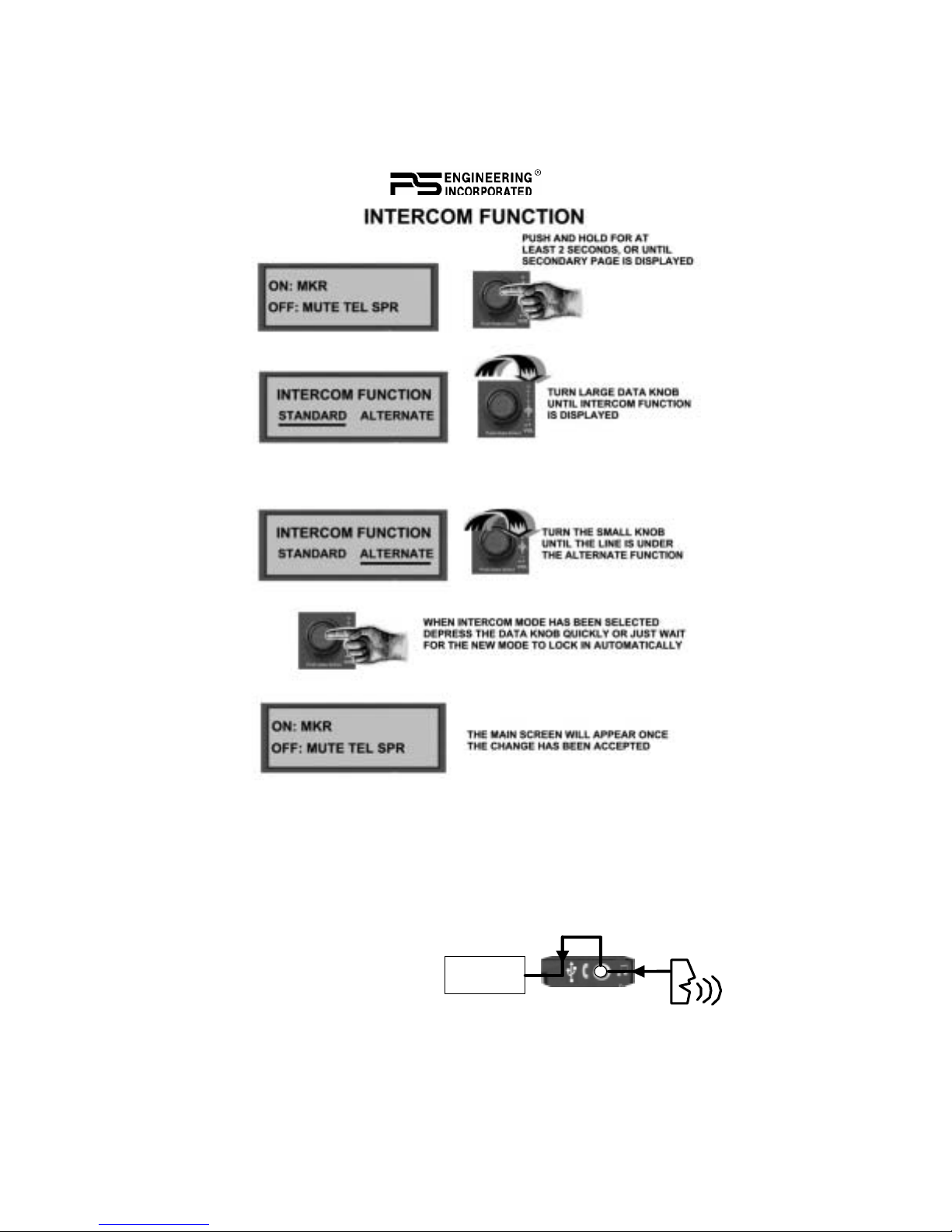
4.2 Standard/Alternate Intercom Function
Alternate Intercom Function is a mode that allows everybody to talk
on the intercom, but the passengers do NOT hear the aircraft radios.
In addition, when the aircraft radios are active, the crew does not hear
the passengers’ microphones, although passengers continue to hear
each other. This function is selected through the ECAPS system.
4.3 Utility Jack (9)
The 2.5-millimeter (3/32”) jack on the front of the PMA9000EX has
three distinct functions:
• Music input
• Advisory audio input
• Wired Cell phone input
4.3.1 Front Jack Music Input
When used as a music input, the front panel jack is treated as Music
#1. However, thanks to the PMA9000EX controls, it can be
202-920-0100 Page 11MAR. 2008 PMA9000EX Pilot Guide
distributed to all users, regardless of the intercom mode. A patch cord
is available with 2.5 mm to 3.5 mm (3/32" to 1/8" ) adapter cord (PS
Part Number 425-006-2535).
4.3.2 Audio Advisory Input
The front jack can be used
as a priority advisory input
for auxiliary systems such
as a GPS terrain advisory or
Crew
Page 12 202-920-0100 PMA9000EX Pilot Guide
portable traffic watch system. To prevent radio or intercom from mut-
ing this input, turn off the “Mute” function.
4.2.2.1 Smart Jack Function
When the PMA9000EX has a signal on music #1 input coming in
from the rear connector, the front panel jack automatically becomes a
Priority Advisory input, and is heard in the crew headphones.
NOTE
The front jack is no substitute for the certified installation of alerts
such as the GPS waypoint or autopilot tones. These still must be hard
wired into the back by your installer.
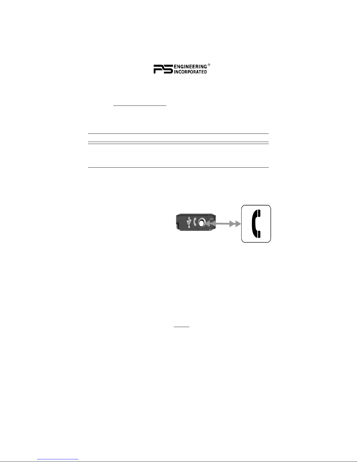
4.3.3 Cellular phone
When a wired cellular telephone is connected to this jack using avail-
able 2.5 mm to 2.5 mm adapter cord (PS Part Number 425-006-7026),
the PMA9000EX audio panel will connect the intercom to the cell
phone when the “TELEPHONE mode is
activated, and behave as de-
scribed in section 3.7. The tele-
phone ringer, if present, will be
heard unless the input is muted
by other radio or intercom., however, with the wired con-
nection, the TELEPHONE RINGING message will not be displayed.
4.3 Telephone (TEL) Mode
The TEL mode serves as a full duplex interface and distribution for
compatible portable cellular phones with hands free jacks or Blue-
tooth capable.
4.3.1 Bluetooth
4.3.1.1 Bluetooth Telephone Connection
Before the PMA9000EX can be used in TEL mode with a wireless
Bluetooth connection, the unit must be associated with a specific
phone.
Activate the “seek device” function on the cell phone, and then enter
the access code “0000” when the phone detects the “PMA9000EX”
on the list of available devices.
This process will be necessary for any phone to be used, and only one
cell phone can be associated with the audio panel at a time. If the

202-920-0100 Page 13MAR. 2008 PMA9000EX Pilot Guide
additional phones are associated with the PMA9000EX at the same
time, only the first phone will transfer audio to the panel.
4.3.1.2 Using Bluetooth
When using Bluetooth, during an incoming call, the PMA9000EX
will automatically display “TELEPHONE RINGING” and play a ring
tone. Pressing the encoder knob will connect the call, if desired. The
PMA9000EX exits the telephone mode automatically when the cellu-
lar phone hangs up.
To make an outgoing call, select TEL using the ECAPS system. Us-
ing the cell phone, dial the desired number and select “connect” on
the cell phone. You now connected to the telephone. NOTE: you will
continue to hear the selected Com. When you press the PTT, the cell
phone will mute.
4.3.2 Telephone Distribution
Entering the TEL mode connects the telephone to the users as fol-
lows:
In ALL intercom mode, all crew and passengers will be heard on the
phone. Com and other selected radio audio is also heard in the head-
sets. If the pilot or copilot pushes the radio PTT, their mic will be
transferred to the selected Com radio. The telephone party will not
hear ATC communications, and vice versa.
In CREW mode, only the pilot and copilot are connected to the tele-
phone. Passengers will not hear the telephone. The pilot and copilot
will also have transmit capability on the other selected transceiver.
In ISO intercom mode, when the PMA9000EX is in the TEL mode,
the pilot position is in the "Phone Booth." Only the pilot will hear the
telephone, and only he will be heard. He will also have access to Com
1 or 2, and will transmit on that radio using the PTT. All selected au-
dio is provided to the pilot.
NOTE: Because the cell-phone uses an intercom circuit, all stations
on that circuit lose intercom capability when the cell phone is in use.
WARNING
FCC regulation 47 CFR 22.925 prohibits the use of 800 MHz Cellular
handsets in any aircraft that is airborne. Violation of this rule could
result in suspension of service and/or a fine.

Page 14 202-920-0100 PMA9000EX Pilot Guide
4.4 Music Input & Distribution
There are three music sources available to the PMA9000EX: MP3,
Music 1, and Music 2. Music 1 input can be either on the front jack,
OR the Music 1 input at the rear connector. Music 2 is wired into the
rear connector only.
The PMA9000EX has two music channels, which can use any of
three sources. One music channel is provided to the crew, and can be
distributed to the passengers. Another music input is dedicated to the
Passengers stations. The three sources, Music 1, Music 2 and MP3
can be directed via the ECAPS to these channels.
202-920-0100 Page 15MAR. 2008 PMA9000EX Pilot Guide
Note: If you don’t ear the music devise as expected, verify which
sources is selected for the crew.
If the MP3 player is selected for the crew, and music is playing in the
front panel jack or Music 1, BOTH sources will be heard, because the
front panel jack can also be used for alert audio and telephone.
Select MUSIC DISTRIBUTION submenu, push the knob, and select
the desired configuration from that menu.
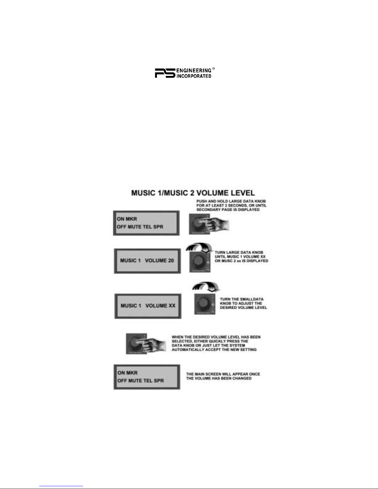
4.4.1 Music Volume
Music #1 volume is controlled by the small data knob at all times,
unless the MP3 player is active, in which case the small data knob
controls MP3 Volume.

Page 16 202-920-0100 PMA9000EX Pilot Guide
In addition, music input 1 and music input 2 have individual volume
controls that are accessible through the ECAPS system. Push the small
data knob for 2 seconds, and then turn the large data knob until MUSIC
1 or MUSIC 2 is shown. Then turn the small data knob to change the
volume. The display will revert and store the values after 3 seconds.
4.4.2 Music Mute Control
PMA9000EX controls the music muting allowing the user to tailor the
SoftMute™ to their taste and situation. There are two SoftMute™ mut-
ing circuits. The SoftMute™ circuit will cut the music almost com-
pletely out whenever there is conversation on the radio or intercom.
When that conversation stops, the music returns to the previous level
comfortably, over a second or so.
For those occasions when the music musing isn’t necessary or desired,
the SoftMute can be disabled from the front panel.
Push the small knob to highlight the cursor. Select the MUTE by
turning the small knob, and push the knob again to toggle mute
on or off. This mute control is for the Crew music only. Passenger
music muting is controlled through a switch installed in a location
convenient to the passengers.

202-920-0100 Page 17MAR. 2008 PMA9000EX Pilot Guide
4.4.3 MP3 On/Off
The internal MP3 player can be turned on and off and the order of play
can be either sequential or random. Each of these functions has a sub-
menu item in the ECAPS system.
The MP3 player resets to off when the PMA9000EX is turned off.
4.4.4 MP3 Volume
The volume of the internal MP3 player can be adjusted at any time the
player is on and main menu is displayed, by turning the small data
knob.

Page 18 202-920-0100 PMA9000EX Pilot Guide
4.4.5 MP3 Music Track selection
The track can be changed whenever the MP3 player is operating by
turning the large data knob. The track title is displayed momentarily.
The display also changes to show the title when the track changes.
4.4.6 MP3 Random Mode
The PMA9000EX MP3 player can be set to play the files in sequence,
or in a random order. The MP3 Random Mode is on the submenu.

202-920-0100 Page 19MAR. 2008 PMA9000EX Pilot Guide
4.4.7 MP3 File Transfer
The PMA9000EX has 1 GB of internal storage (512 MB before S/N
B01094). The program inside the unit will recognize and import any
compatible audio files (.wav, .mp3, unprotected .wma) from an external
data source, through the USB cable. These files must be in the device’s
root directory to be recognized, and not located in any subfolders.

Page 20 202-920-0100 PMA9000EX Pilot Guide
To upload from a USB memory device, select the “Music Transfer”
function on the submenu. Follow the onscreen instructions, and connect
the memory device to the 2.5mm to USB cable, and then plug the cable
into the front of the PMA9000EX when prompted. It will take about 30
minutes to transfer 1Gigabyte of data.
Files are loaded from the USB in the order that they are stored. We rec-
ommend that you only store 1G (512MB before Serial Number
B01094) of files on the USB drive, to ensure that all the desired songs
are loaded into the PMA9000EX.
After the music transfer is complete, the PMA9000EX will automati-
cally reset to store the files and create the new play list. Therefore it is
not advisable to upload files in flight or when the audio panel is other-
wise in use.
Note: Different types of files, and different music file programs may
result in variation in the volume level of the stored music.
4.4.7.1 Laptop connection
Using the supplied 2.5mm-to-USB cable, along with the supplied USB-
to-USB adapter cord (PS Part number 425-003-1454), connect this set
of cables from the PMA9000EX front panel jack to a Personal Com-
puter USB port.
With the PMA9000EX turned off, push and hold the small data knob
while powering the PMA9000EX on. Wait until the audio panel dis-
plays "USB drive mode" before releasing. You then can access the
PMA9000EX as if it were an external USB drive. This mode allows for
file transfer rates nearly four times faster than the direct USB connec-
tion.
Table of contents


