Enginious MX-100 User manual
© 2007 Enginious. All Rights Reserved.
2-Channel Digital
Audio Mixer User Manual
Enginious MX-100
Digital Audio Mixer
http://www.enginious.info

© 2007 Enginious. All Rights Reserved. Page 2 of 14
I. CONTENTS
A. Table of Contents
I. CONTENTS .................................................................................................................... 2
A. Table of Contents ....................................................................................................... 2
B. List of Tables.............................................................................................................. 2
C. List of Figures ............................................................................................................ 2
II. WARNINGS .................................................................................................................. 3
A. Hearing Warning..................................................................................................... 3
B. Power Warning........................................................................................................... 3
C. Liquid Warning .......................................................................................................... 3
D. Copyright Warning .................................................................................................... 3
III. CARE AND MAINTANANCE ................................................................................... 4
IV. INTRODUCTION ........................................................................................................ 5
V. FEATURES ................................................................................................................... 6
VI. SETUP .......................................................................................................................... 7
VII. CONTROLS.............................................................................................................. 10
VIII. APPENDIX.............................................................................................................. 12
A. Specifications ........................................................................................................... 12
B. Barrier Strip Connections......................................................................................... 13
C. Contact Information ................................................................................................. 14
B. List of Tables
Table 1 - Control Identification ........................................................................................ 11
Table 2 - Barrier Strip Connections ................................................................................. 14
C. List of Figures
Figure 1 - Device Power Socket ......................................................................................... 7
Figure 2 - Input/Output Jacks ............................................................................................. 7
Figure 3 - Monitor Headphone Jacks.................................................................................. 8
Figure 4 - Fuse Holder ........................................................................................................ 8
Figure 5 - Power Switch ..................................................................................................... 9
Figure 6 - Control Panel.................................................................................................... 10
Figure 7 - Back Panel Barrier Strips ................................................................................. 13
Figure 8 - Front Panel Barrier Strips................................................................................. 13
© 2007 Enginious. All Rights Reserved. Page 3 of 14
II. WARNINGS
A. Hearing Warning
B. Power Warning
C. Liquid Warning
D. Copyright Warning
Warning: To reduce the risk of electric shock, do not
disassemble this product. Take it to a certified specialist
when service or repair work is required.
Warning: Permanent hearing loss may occur if
earphones, headphones, or speakers are used at high
volume. You can adapt over time to a higher volume of
sound, which may sound normal but can be damaging to
your hearing. Set your mixer’s volume to a safe level
before that happens.
Warning: Enginious does not represent this unit to be
waterproof. To reduce the risk of fire, electrical shock,
or damage to the unit, do not expose this unit to rain or
moisture or immerse in water.
Warning: Enginious is not responsible for the misuse of
copyrighted materials modified on the unit.

© 2007 Enginious. All Rights Reserved. Page 4 of 14
III. CARE AND MAINTANANCE
•Wipe unit with a damp cloth occasionally to clean. Do not use harsh chemicals,
cleaning solvents, or strong detergents.
•Do not allow anything to rest on the power cord.
•Do not locate this product where persons walking on it could damage the cord.
Keep cord away from heated surfaces.
•To disconnect, grip the power plug and pull it from the wall outlet or unit. Never
disconnect by pulling on the cord.
•This product is designed to operate using the either 120V AC at 60Hz or 240V
AC at 50Hz.
•GLCD screens can change color in extreme temperatures. If the unit is exposed to
temperatures below -20
o
C (-5
o
F) or above +60
o
C (+140
o
F), the display may
temporarily cease to function properly, or could result in permanent damage.

© 2007 Enginious. All Rights Reserved. Page 5 of 14
IV. INTRODUCTION
CONGRATULATIONS on your purchase of the Enginious brand 2-Channel
Digital Audio Mixer, Model MX-100. You have chosen a terrific mixer which allows
up to 2-channels to be inputted to the device that can come from a variety of audio
sources including MP3 players, CD players, computers, etc… The device will take
these inputs and process both digitally to give you quality sound with features you’ll
love including 3-band equalizer, volume control, monitor functionality, GLCD
display, easy-to-learn controls, and many more.

© 2007 Enginious. All Rights Reserved. Page 6 of 14
V. FEATURES
The main features of the MX-100 Audio Mixer are:
•2-Channel Input – able to input two different audio sources which include a
variety of devices that output analog audio signals like MP3 players,
microphones, etc…
•Digital Processing – both input channels are processed digitally to give a higher
quality of sound.
•3-Band Equalizer – including bass, mid, and treble control.
•GLCD Display – beautiful 128x64 GLCD display used currently for product info.
•Monitor Functions – user is able to mix the music through headphones before
outputting it to their audience.

© 2007 Enginious. All Rights Reserved. Page 7 of 14
VI. SETUP
To properly setup the device, follow the steps below:
1. Plug the female end of the power cable to the power socket on the back panel of
the device and insert the male end of the power cable into a 120V AC at 60Hz or
240V AC at 50Hz wall socket. The male socket on the back panel of the device is
shown in Figure 1.
Figure 1 - Device Power Socket
2. Plug in the input devices into Channel #1 and #2 RCA or 1/8” jacks on the back
panel of the device. Channel #1 is the three vertical jacks to the far left, Channel
#2 is the three vertical jacks in the middle, and the output is the three vertical
jacks on the far right. Now plug in the output to amplifier/speakers from the
RCA or 1/8” jacks to the far right also on the back panel of the device. Figure 2
shows the input and output hardware.
Figure 2 - Input/Output Jacks

© 2007 Enginious. All Rights Reserved. Page 8 of 14
3. Plug in your headphones into the either the ¼” or 1/8” monitor jacks located on
the front of the device on the left side. Figure 3 shows both jacks.
Figure 3 - Monitor Headphone Jacks
4. Now, a 1 AMP (1x1/4x1/4”) fuse must be properly installed into the device. The
fuse holder is located on the rear panel of the device. Unscrew the cap counter-
clockwise, place the 1 AMP fuse inside the holder, and screw back the cap
clockwise. The fuse holder is shown in Figure 4.
Figure 4 - Fuse Holder

© 2007 Enginious. All Rights Reserved. Page 9 of 14
5. Next, the device has to be turned on. Before turning the device on, make sure
volume controls are set to a proper level in order to protect the hearing of others
and yourself. The power switch is located on the device’s rear panel on the lower
right. Figure 5 shows the power switch.
Figure 5 - Power Switch
© 2007 Enginious. All Rights Reserved. Page 10 of 14
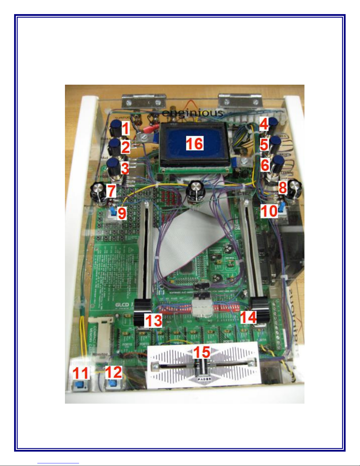
VII. CONTROLS
The control panel of the device is shown in Figure 6 and the corresponding controls
table is shown in Table 1.
Figure 6 - Control Panel

© 2007 Enginious. All Rights Reserved. Page 11 of 14
Number
Control
1 Channel #1 Bass
2 Channel #1 Mid
3 Channel #1 Treble
4 Channel #2 Bass
5 Channel #2 Mid
6 Channel #2 Treble
7 Monitor Volume
8 Main Volume
9 Channel #1 On/Off
10 Channel #2 On/Off
11 Monitor Channel #1
On/Off
12 Monitor Channel #2
On/Off
13 Channel #1 Volume
14 Channel #2 Volume
15 Crossfader
16 GLCD
Table 1 - Control Identification

© 2007 Enginious. All Rights Reserved. Page 12 of 14
VIII. APPENDIX
A. Specifications
The specifications of the device are listed below.
•Input Channels: Analog
•Number of Input Channels: 2
•Mono/Stereo: Mono
•Sampling Rate: 44.1kHz/channel (CD Quality Audio)
•Equalizer: Three-Band (Bass, Mid, and Treble)
•Power Source: 120V AC at 60Hz or 240V AC at 50Hz
•Power Consumption: < 20 Watts
•Dimensions: 6” x 10” x 13.5” (H x W x L)
•Weight: 10Ibs.

© 2007 Enginious. All Rights Reserved. Page 13 of 14
B. Barrier Strip Connections
Figure 7 - Back Panel Barrier Strips
Figure 8 - Front Panel Barrier Strips

© 2007 Enginious. All Rights Reserved. Page 14 of 14
Wire Terminal Chart
Segment
Connection
Control
Panel
Development
Board Notes
1
CH1 SWITCH RF0 First Barrier Strip (2 positions)
2
CH2 SWITCH RF1
3
CH1 BASS A RB0 Second Barrier Strip (11 positions)
4
CH1 BASS B RB1
5
CH1 MID A RF2
6
CH1 MID B RF3
7
CH1 TRE A RF4
8
CH1 TRE B RF5
9
CH2 BASS A RG0
10
CH2 BASS B RG1
11
CH2 MID A RG2
12
CH2 MID B RG3
13
CH2 TRE A RG12
14
CH2 Input Non-Mod N/A Third Barrier Strip (11 positions)
15
CH1 Input Non-Mod N/A
16
CH2 Input MOD RB9 To MCU
17
CH1 Input MOD RB10 To MCU
18
Main Volume Input N/A Input to Main Volume Potentiometer
19
CH2 TRE B RG13
20
Ground N/A
Used for Outputs (Output Pot and Output
Jacks). Goes to DAC (Ground #2).
21
Mic Input Non-Mod N/A
22
Monitor Output N/A
23
5V VCC
24
Ground GND Used for Inputs and Controls (Ground #1).
Table 2 - Barrier Strip Connections
C. Contact Information
Phone: Muhannad Alkhurafi
E-mail: malkhurafi@mac.com
Charles Castello
Diego Oubina
E-mail: doubina@funbox3d.com
Website: http://www.enginious.info
Table of contents


