Enginko MCF-LW06424 User manual

m2m Germany GmbH | Am Kappengraben 18-20 | 61273 Wehrheim | 06081 5873860
Table
of
Contents
MCF-LW06424
Operating
Manual
Important
safety
information
Read
this
manual
before
attempting
to
install
the
device!
Failure
to
observe
recommendations
included
in
this
manual
may
be
dangerous
or
cause
a
violation
of
the
law.
The
manufacturer
will
not
be
held
responsible
for
any
loss
or
damage
resulting
from
not
following
the
instructions
of
this
operating
manual.
Do
not
dismantle
or
modify
in
any
way.
Avoid
mechanical
stress
Do
not
use
any
detergent
or
alcohol
to
clean
the
device.
Disposal
information
for
users
Pursuant
to
and
in
accordance
with
Article
14
of
the
Directive
2012/19/EU
of
the
European
Parliament
on
waste
electrical
and
electronic
equipment
(WEEE),
and
pursuant
to
and
in
accordance
with
Article
20
of
the
Directive
2013/56/EU
of
the
European
Parliament
on
batteries
and
accumulators
and
waste
batteries.
The
barred
symbol
of
the
rubbish
bin
shown
on
the
equipment
indicates
that,
at
the
end
of
its
useful
life,
the
product
must
be
collected
separately
from
other
waste.
Please
note
that
the
lithium
batteries
must
be
removed
from
the
equipment
before
it
is
given
as
waste
and
disposed
separately.
To
remove
the
batteries
refer
to
the
specifications
in
the
user
manual.
For
additional
information
and
how
to
carry
out
disposal,
please
contact
the
certified
disposal
service
providers.
1.
Description
MCF-LW06424
is
able
to
read
4
analog
inputs
4-20mA
with
a
resolution
of
12
bit.
The
inputs
have
an
insulation
of
1000Vdc
with
respect
to
the
power
supply,
and
are
protected
against
polarity
inversion.

m2m Germany GmbH | Am Kappengraben 18-20 | 61273 Wehrheim | 06081 5873860
MCF-LW06424
is
available
with
DIN
rail
option
(MCF-DIN105):
2.
Overview
2.1
Technical
data
CPU
Cortex
M4
RTC
EEProm
32KB
Flash
1MB
Encryption
AES
128
bit
LiPo
800mAh
rechargeable
battery
Class
C
LoRaWAN®
stack
EU868,
AS923,
AU915,
US915
1000Vdc
isolated
analog
inputs
4
analog
current
inputs
4-20mA
12bits
and
disconnect
alarm
4
programable
thresholds
for
each
channel
USB
On
The
Go
IoT
node
setup
ad
firmware
upgrade
via
USB
interface
Power
supply
10÷36Vdc
Storage
temperature
range
-20°C
÷
+80°C
Working
temperature
range
-10°C
÷
+70°C
Dimensions
L
x
H
X
P:
81
x
60
x
50mm
3
Installation
3.1
Connection
3.1.1
Power
connection
as
stand-alone
device
Please
refer
to
following
connections:

m2m Germany GmbH | Am Kappengraben 18-20 | 61273 Wehrheim | 06081 5873860
pin
Name
Description
J3.9
GND
Negative
power
supply
(BLACK)
J3.10
VDD
Positive
power
supply
range
[10-36Vdc]
(RED)
Power
can
also
be
supplied
by
USB.
3.1.2
Power
connection
with
DIN
rail
option
Please
refer
to
following
connections:
Power
supply:
Pin
Name
Description
J2.1
Vdc
Positive
power
supply
range
[10-36Vdc]
J2.2
GND
Negative
power
supply
Power
can
also
be
supplied
by
USB.
3.1.3
Antenna
The
magnetic
antenna
must
be
positioned
on
ametal
body.
It
should
preferably
be
vertical
and
at
least
30
cm
away
from
other
metal
bodies.
The
installation
must
take
place
in
a
place
where
the
LoRaWAN®
signal
coverage
is
good
(SF=7
optimal,
SF=12
weak).
Use
the
provided
clip
to
hold
the
antenna
connector
in
place,
as
in
the
picture:
3.2
Analog
inputs
m2m Germany GmbH | Am Kappengraben 18-20 | 61273 Wehrheim | 06081 5873860
125Ω
1000Vdc
Pin
Name
Description
Range
Resolution
J1.1
AI1
Analog
input
1
4-20mA
12
bit
J1.2
GA
Common
J1.3
AI2
Analog
input
2
4-20mA
12
bit
J1.4
GA
Common
J1.5
AI3
Analog
input
3
4-20mA
12
bit
J1.6
GA
Common
J1.7
AI4
Analog
input
4
4-20mA
12
bit
J1.8
GA
Common
Current
Loop
(4-20mA)
Input
resistance
Absolute
maximum
value
24mA
Max
error
±0.1%
Insulation
Current
values
less
than
3mA
generate
a
“disconnected
sensor”
condition.
Caution:
inputs
are
not
galvanically
isolated
from
each
other.
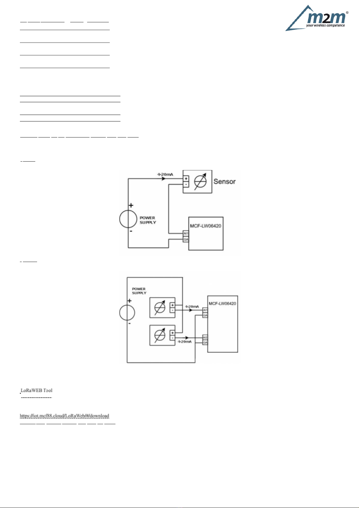
3.2.1
Connection
examples
1
sensor
2
sensors
3.3
Configuration
To
deploy
the
sensor,
use
LoRaWEB
online
tool,
to
setup
LoRaWAN®
credentials
and
other
preferences
(only
available
for
Windows®)
:
(iot.mcf88.cloud/LoRaWeb)
Before
connect
the
device
the
first
time,
please
install
LoRaBridge
applications
and
drivers:
Validate
your
settings
reading
data
after
the
write.
enginko
provides,
upon
free
registration,
user
manuals,
javascript
examples,
downlink
generator,
uplink
decoder,
firmware
updates
and
different
tools
:

m2m Germany GmbH | Am Kappengraben 18-20 | 61273 Wehrheim | 06081 5873860
Quick
flashing
Quick
flashing
Quick
flashing
Fixed
Flashing
2
seconds
Flashing
1
second
3.4
System
led
LoRaWAN®
not
configured Slow
flashing
Joining
Sending
Receiving
Steady
state
Data
error
Connection
error
3.5
Firmware
update
Save
the
new
firmware
file
(.exe)
on
the
PC,
run
the
file,
select
the
USB
FW
port
and
start
the
update:
and
waiting
for
the
end
message.
4.
Setup
m2m Germany GmbH | Am Kappengraben 18-20 | 61273 Wehrheim | 06081 5873860
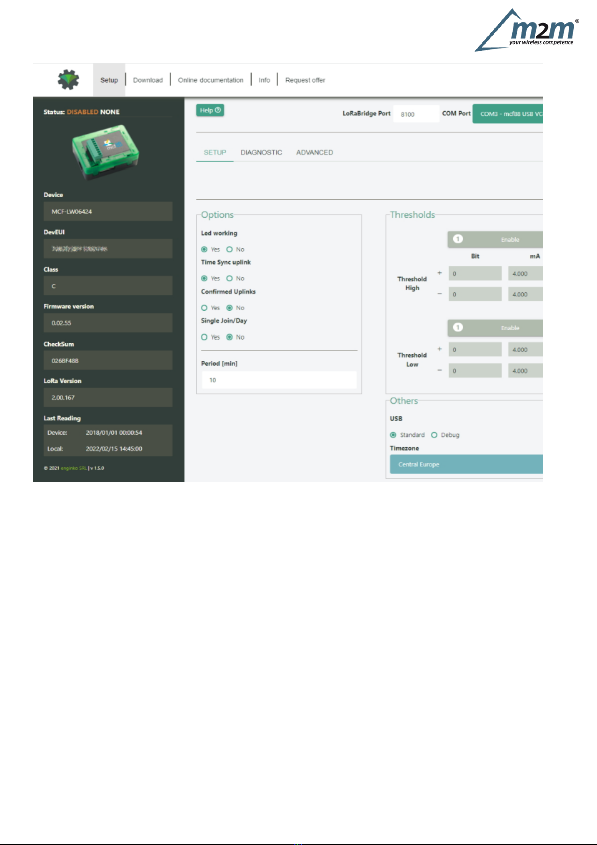
4.1
Period
Period
is
the
interval
(in
minutes)
between
one
measure
and
the
next
one.
The
sensor
sends
one
measures
for
every
transmission.
Value
can
be
between
15
and
65535
minutes
(default:
30
minutes).
Period
interval
can
be
set
with
LoRaWEB
or
with
downlink
command.
4.2
Thresholds

m2m Germany GmbH | Am Kappengraben 18-20 | 61273 Wehrheim | 06081 5873860
On
the
MCF-LW06424
is
possible
to
set
4
thresholds
for
each
channel:
Th+
=
Threshold
High
Rising
Th-
=
Threshold
High
Falling
Tl+
=
Threshold
Low
Rising
Tl-
=
Threshold
Low
Falling
When
target
values
are
rising
and
exceed
the
positive
thesholds,
the
device
sends
an
uplink
with
the
the
latest
measure.
Whenvalues
are
falling
below
the
negative
thresholds,
the
device
sends
a
new
uplink
with
the
latest
measure.
Thresholds
can
be
enabled,
disabled
and
changed
va
USB
with
LoRaWEB
or
with
downlinks:

m2m Germany GmbH | Am Kappengraben 18-20 | 61273 Wehrheim | 06081 5873860
4.3
Other
settings
DST:
set
to
change
DST
(default:
none).
Time
sync
uplink:
set
to
disable
time
synchronization
request
(default:
enabled).
Normally
sensor
asks
for
a
time
sync
at
every
power
on
(uplink
starting
with
01)
or
once
a
week.
If
no
or
wrong
reply
received,
it
will
retry
after
1
week.
If
not
handled
in
the
right
way
can
generate
unnecessary
traffic
on
the
network.
Please
check
chapter
2.1
.
Confirmed
Uplinks:
set
for
unconfirmed
uplinks
(default:
confirmed
uplink).
Single
join/day:
set
for
to
allow
only
one
join
per
day
(default:
multiple
join
allowed).
LED
working:
Set
OFF
to
turn
off
the
diagnostic
led.
USB:
Internal
use.
5.
Diagnostic
m2m Germany GmbH | Am Kappengraben 18-20 | 61273 Wehrheim | 06081 5873860
Press
Check
to
see
the
analog
values.
6
LoRaWAN
network
The
sensor
is
compliant
with
LoRaWAN®
specification
1.0.2,
regional
1.0.2b.
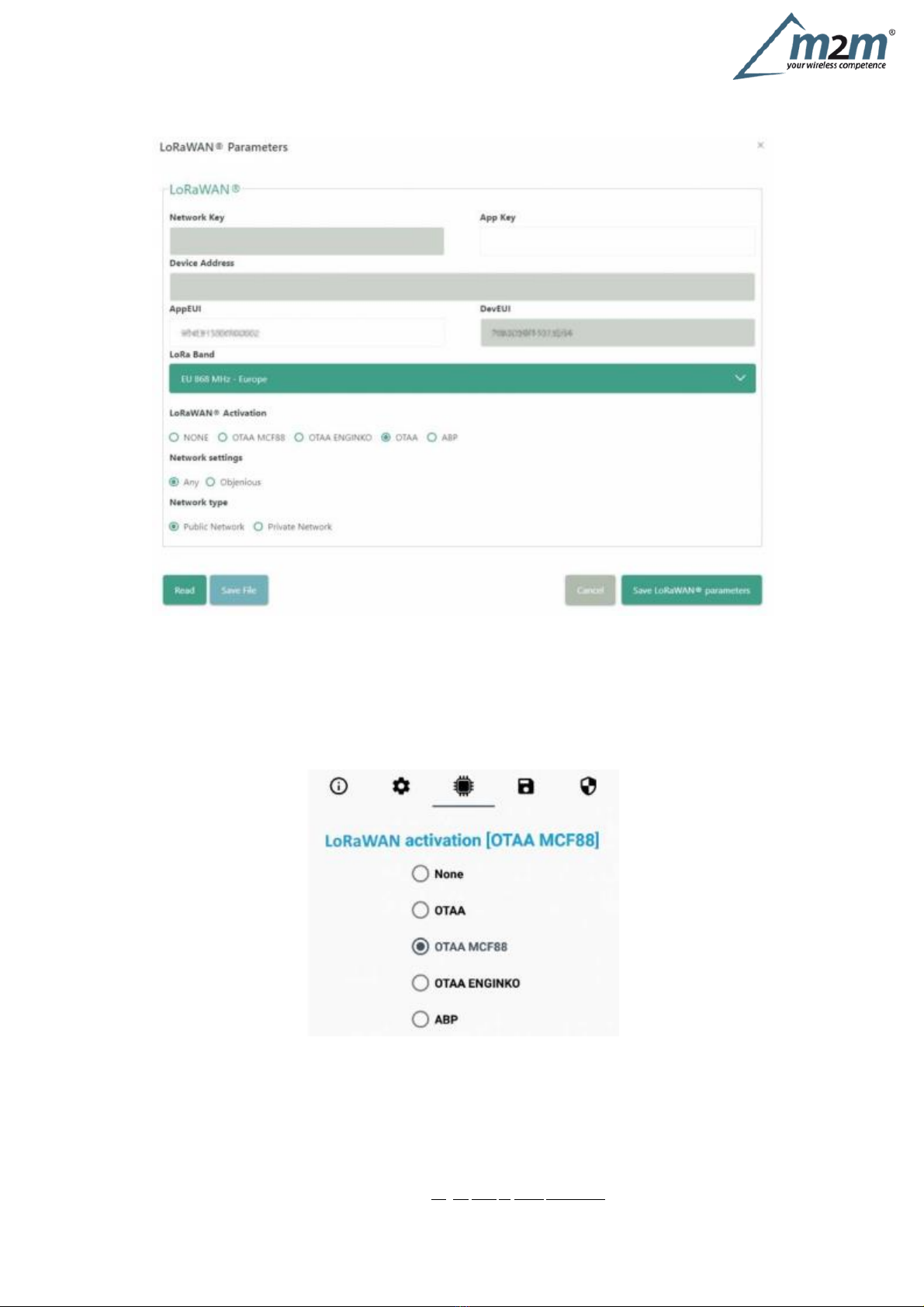
6.1
Activation
The
device
supports
the
following
activations
on
a
LoRaWAN®
network:
1.
NONE:
sensor
not
activated
2.
OTAA:
the
JoinEUI
and
the
AppKey
not
setted,
must
be
written
to
the
device;
3.
OTAA
MCF88:
Over
the
air
activation,
fixed
keys:
JoinEUI
=
904e915000000002,
AppKey
on
request;
4.
OTAA
ENGINKO:
Over
the
air
activation,
fixed
keys:
JoinEUI
=
904e915000000002,
AppKey
on
request;
5.
ABP:
requires
writing
to
the
device
of
NwkSkey,
AppSkey,
DevAddr.
The
device
exits
factory
activated
with
NONE
mode.
On
request
devices
can
be
shipped
already
activated.
Note:
in
OTAA
AppKey
is
write
only,
in
reading
the
field
will
always
be
empty,
even
if
set.
6.2
Other
settings
Network
settings:
please
keep
“Any”
settings.
Change
it
only
if
Objenious
network
is
used
(default_
any).
Network
type:
LoRa
syncword
can
be
setted
as
“private”(0x12)
instead
“public”
(0x34),
butthe
NS
must
be
setted
accordingly(default:
public).
Band:
select
the
right
LoRaWAN
®
band
settings
accodingly
to
country
requirements.
m2m Germany GmbH | Am Kappengraben 18-20 | 61273 Wehrheim | 06081 5873860
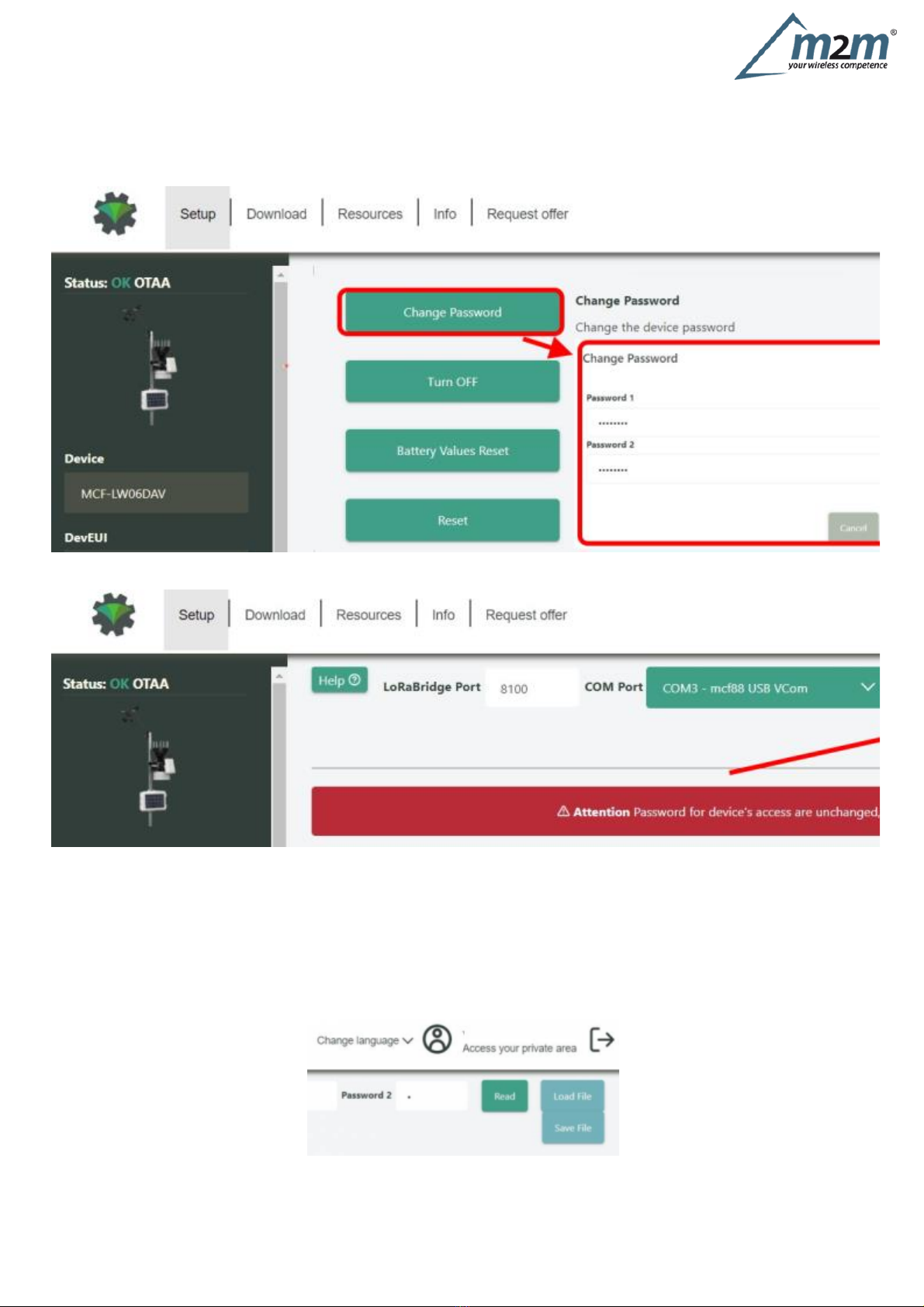
7
Passwords
The
device
can
be
protected
by
passwords,
to
avoid
unauthorized
persons
to
read
data
or
modify
parameters.
As
default
passwords
are
equal
to
0.
Allowedvalues
range
from
0
to
999999999
(only
numbers).
To
change
the
passwords,
set
the
new
values
with
LoRaWEB:
Once
the
passwords
are
setted,
to
gain
access
from
LoRaWEB
to
the
sensor,
set
the
right
values
before
reading
from
the
device:
To
bring
back
the
sensor
to
factory
default
and
reset
the
passwords,
a
reset
code
must
be
requested
to
enginko
(please
provide
the
DevEUI
of
the
sensor
when
you
ask
for
that
code).
8
General
configuration
file
WIth
LoRaWEB
is
possible
to
configure
the
device
using
an
XML
file,
instead
to
manually
adjust
the
parameters
(for
details
about
the
file
format
please
ask
to
enginko).
This
is
very
useful
especially
in
case
of
multiple
devices
configuration.
With
“Save”
button
an
XML
file
with
the
actual
configuration
of
the
sensor
will
be
generated.
This
is
useful
to
store
or
clone
the
configuration,
or
to
send
it
to
enginko's
support
if
needed.
8.1
Multi
devices
configuration
WIth
LoRaWEB
is
possible
to
configure
many
devices
in
an
easy
way.
For
multi-configuration
is
needed
at
least
one
XML
file
with
the
parameters
to
set.

m2m Germany GmbH | Am Kappengraben 18-20 | 61273 Wehrheim | 06081 5873860
4-20mA
to
LoRaWAN®
interface
EU863-870
Settings
on
this
file
will
be
applied
to
all
the
sensors.
With
an
additional
XLS
file
is
possible
to
load
different
LoRa
configuration
parameters
(Activation
Type,
AppKey,
AppEUI,
NetKey,
DevAddress,
Band,
Private
option)
for
each
sensor,
based
on
DevEUI.
XLS
is
prevailing
on
the
XML,
so
if
both
files
are
enabled,
if
the
DevEUI
of
the
device
matches
one
of
the
DevEUIs
in
the
XLS
file,
LoRa
parameters
will
be
setted
from
this
one.
These
configuration
can
be
done
in
the
in
the
Settings:
Use
of
the
general
configuration
by
file;
Use
of
the
specific
configuration
by
file.
For
details
on
files
format
please
ask
to
enginko.
9
Payload
For
payload
descriptions,
uplinks
and
downlinks
format
and
available
commands
please
refer
to
this
document:
10
Ordering
code
Code
MCF-LW06424
Description
MCF-LW06424-AS
4-20mA
to
LoRaWAN®
interface
AS920-925
MCF-LW06424-US
4-20mA
to
LoRaWAN®
interface
US902-928
MCF-LW06424-AU
4-20mA
to
LoRaWAN®
interface
AU915-928
For
payload
descriptions,
uplinks
and
downlinks
format
and
available
commands
please
refer
to
this
document:

m2m Germany GmbH | Am Kappengraben 18-20 | 61273 Wehrheim | 06081 5873860
11
Declaration
of
conformity
Hereby,
enginko
Srl
declares
that
MCF-LW06424
complies
with
the
essential
requirements
and
other
relevant
provisions
of
Directive
2014/53/EU.
12
FCC
compliance
for
MCF-LW06424-US
This
device
complies
with
part
15
of
the
FCC
Rules.
Operation
is
subject
to
the
following
two
conditions:
(1)
This
device
may
not
cause
harmful
interference,
and
(2)
this
device
must
accept
any
interference
received,
including
interference
that
may
cause
undesired
operation.
This
equipment
has
been
tested
and
found
to
comply
with
the
limits
for
a
Class
B
digital
device,
pursuant
to
part
15
of
the
FCC
Rules.
These
limits
are
designed
to
provide
reasonable
protection
against
harmful
interference
in
a
residential
installation.
This
equipment
generates,
uses
and
can
radiate
radio
frequency
energy
and,
if
not
installed
and
used
in
accordance
with
the
instructions,
may
cause
harmful
interference
to
radio
communications.
However,
there
is
no
guarantee
that
interference
will
not
occur
in
a
particular
installation.
If
this
equipment
does
cause
harmful
interference
to
radio
or
television
reception,
which
can
be
determined
by
turning
the
equipment
off
and
on,
the
user
is
encouraged
to
try
to
correct
the
interference
by
one
or
more
of
the
following
measures:
m2m Germany GmbH | Am Kappengraben 18-20 | 61273 Wehrheim | 06081 5873860
Reorient
or
relocate
the
receiving
antenna.
Increase
the
separation
between
the
equipment
and
receiver.
Connect
the
equipment
into
an
outlet
on
a
circuit
different
from
that
to
which
the
receiver
is
connected.
Consult
the
dealer
or
an
experienced
radio/TV
technician
for
help.
Any
changes
or
modifications
not
expressly
approved
by
the
party
responsible
for
compliance
could
void
the
user’s
authority
to
operate
this
equipment.
Contains
FCC
ID:
2AWAL409810
13
Contacts
enginko
Srl
Via
Roma
3
I-28060
Sozzago
(NO)
T
:
+39
0321
15
93
088
E
:info@enginko.com
PEC:enginkosrl@legalmail.it
W:enginko.com
rev.0
Other manuals for MCF-LW06424
1
Table of contents
Other Enginko Recording Equipment manuals


