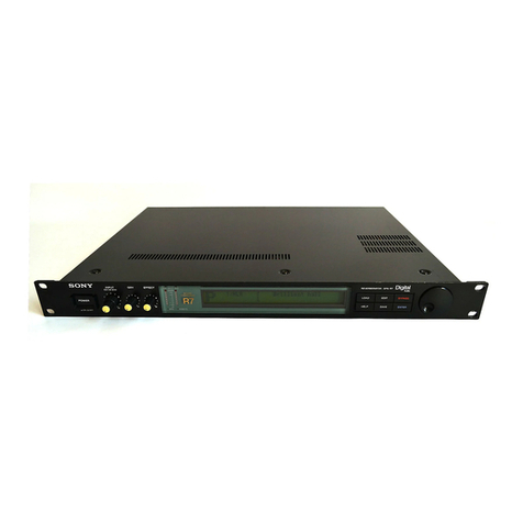
Sony DPS-R7 User manual

SONY
Digital
Reverberator
perating
Instructions
DPS-R7

WARNING
FOR
CUSTOMERS
IN
THE
UNITED
STATES
Owner’s
Record
The
model
and
serial
numbers
are
located
on
the
left
side.
Record
these
numbers
in
the
spaces
provided
below.
Refer
to
these
numbers
whenever
you
call
upon
your
Sony
dealer
regarding
this
product.
Model
No.
DPS-R7
Serial
No.
To
prevent
fire
or
shock
hazard,
do
not
expose
the
unit
to
rain
or
moisture.
CAUTION
RISK
OF
ELECTRIC
SHOCK
DO
NOT
OPEN
CAUTION:
TO
REDUCE
THE
RISK
OF
ELECTRIC
SHOCK,
DO
NOT
REMOVE
COVER
(OR
BACK).
NO
USER-SERVICEABLE
PARTS
INSIDE.
REFER
SERVICING
TO
QUALIFIED
SERVICE
PERSONNEL.
This
symboi!
is
intended
to
alert
the
user
to
the
presence
of
uninsulated
“dangerous
voltage”
within
the
prod-
uct’s
enclosure
that
may
be
of
suffi-
cient
magnitude
to
constitute
a
risk
of
electric
shock
to
persons.
This
symbol
is
intended
to
alert
the
user
to
the
presence
of
important
operating
and
maintenance
(servicing)
instructions
in
the
literature
accompa-
nying
the
appliance.
\
For
detailed
safety
precautions,
see
the
leaflet
“IMPORTANT
SAFEGUARDS”.
2
INFORMATION
This
equipment
generates
and
uses
radio
frequency
energy
and
if
not
installed
and
used
properly,
that
is,
in
strict
accordance
with
the
manufacturer’s
instructions,
may
cause
interference
to
radio
and
television
reception.
It
has
been
type
tested
and
found
to
comply
with
the
limits
for
a
Class
B
computing
device
in
accordance
with
the
specifications
in
Subpart
J
of
Part
15
of
FCC
Rules,
which
are
designed
to
provide
reasonable
protection
against
such
interference
in
a
residential
installation.
However,
there
is
no
guarantee
that
interference
will
not
occur
in
a
particular
installation.
If
this
equipment
does
cause
interference
to
radio
or
television
reception,
which
can
be
determined
by
turning
the
equipment
off
and
on,
the
user
is
encouraged
to
try
to
correct
the
interference
by
one
or
more
of
the
following
measures:
Reorient
the
receiving
antenna
Relocate
the
equipment
with
respect
to
the
receiver
Move
the
equipment
away
from
the
receiver
Plug
the
equipment
into
a
different
outlet
so
that
equipment
and
receiver
are
on
different
branch
circuits.
If
necessary,
the
user
should
consult
the
dealer
or
an
experienced
radio/television
technician
for
additional
suggestions.
The
user
may
find
the
following
booklet
prepared
by
the
Federal
Communications
Commission
helpful:
“How
to
Identify
and
Resolve
Radio-TV
Interference
Problems”’.
This
booklet
is
available
from
the
U.S.
Government
Printing
Office,
Washington,
DC
20402,
Stock
No.
004-000-00345-4,
e
The
shielded
interface
cable
recommended
in
this
manual
must
be
used
with
this
equipment
in
order
to
comply
with
the
limits
for
a
computing
device
pursuant
to
Subpart
J
of
Part
15
of
FCC
Rules.
FOR
CUSTOMERS
IN
CANADA
CAUTION:
TO
PREVENT
ELECTRIC
SHOCK,
DO
NOT
USE
THIS
POLARIZED
AC
PLUG
WITH
AN
EXTENSION
CORD,
RECEPTACLE
OR
OTHER
OUTLET
UNLESS
THE
BLADES
CAN
BE
FULLY
INSERTED
TO
PREVENT
BLADE
EXPOSURE.
This
apparatus
complies
with
the
Class
B
limits
for
radio
noise
emissions
set
out
in
Radio
Interference
Regulations.

FOR
CUSTOMERS
IN
THE
UNITED
KINGDOM
WARNING
THIS
APPARATUS
MUST
BE
EARTHED
IMPORTANT
The
wires
in
this
mains
lead
are
coloured
in
accordance
with
the
following
code:
Green-and-yellow:
Earth
Blue:
Neutral
Brown:
Live
As
the
colours
of
the
wires
in
the
mains
lead
of
this
apparatus
may
not
correspond
with
the
coloured
markings
identifying
the
terminals
in
your
plug
proceed
as
follows:
The
wire
which
is
coloured
green-and-yellow
must
be
connected
to
the
terminal
in
the
plug
which
is
marked
by
the
letter
E
or
by
the
safety
earth
symbol
+
or
coloured
green
or
green-and-yellow.
The
wire
which
is
coloured
blue
must
be
connected
to
the
terminal
which
is
marked
with
the
letter
N
or
coloured
black.
The
wire
which
is
coloured
brown
must
be
connected
to
the
terminal
which
is
marked
with
the
letter
L
or
coloured
red.
Precautions
On
Safety
e
To
avoid
electrical
shock,
do
not
open
the
cabinet.
Refer
servicing
to
qualified
personnel
only.
e
Before
connecting
the
unit
to
the
power
source,
check
that
the
operating
voltage
of
your
unit
is
the
same
as
the
local
power
line
voltage.
The
operating
voltage
is
indicated
on
the
nameplate
on
the
left
side
of
the
unit.
«
Should
anything
fall
into
the
cabinet,
unplug
the
unit
and
have
it
checked
by
qualified
personnel
before
operating
it
any
further.
e
If
the
unit
will
not
be
used
for
an
extended
period,
unplug
it
from
the
wall
outlet.
To
disconnect
the
cord,
pull
it
out
by
the
plug.
Never
pull
the
cord
itself.
e
The
unit
is
not
disconnected
from
the
mains
(AC
power
source)
as
long
as
it
is
connected
to
the
mains
outlet,
even
if
the
unit
itself
has
been
turned
off.
suolnesaig
/HuWweR
On
Installation
e
Allow
adequate
air
circulation
to
prevent
internal
heat
build-
up.
e
Do
not
place
the
unit
on
a
surface
(rugs,
blankets,
etc.)
or
near
materials
(curtains,
draperies,
etc.)
that
may
block
the
ventilation
holes.
e
Do
not
install
the
unit
near
heat
sources
such
as
radiators
or
air
ducts
or
in
a
place
subject
to
direct
sunlight,
excessive
dust,
mechanical
vibration
or
shock.
e
The
unit
is
designed
for
operation
in
a
horizontal
position.
Do
not
install
it
in
an
inclined
position.
e
Keep
the
unit
away
from
equipment
with
strong
magnets,
such
as
microwave
ovens
or
large
loudspeakers.
«Do
not
place
any
heavy
object
on
the
unit.
On
Operation
e
When
the
unit
is
not
in
use,
turn
the
power
off
to
conserve
energy
and
to
extend
its
life.
On
Cleaning
e
Clean
the
cabinet,
panel
and
controls
with
a
dry
soft
cloth,
or
a
soft
cloth
slightly
moistened
with
a
mild
detergent
solution.
e
Do
not
use
any
type
of
solvents,
such
as
alcohol
or
benzine,
which
might
damage
the
finish.
On
Repacking
e
Do
not
throw
away
the
carton
and
packing
materials.
They
make
an
ideal
container
to
transport
the
unit.
If
you
have
any
questions
about
the
unit,
contact
your
Sony
service
facility.
CAUTION!
Danger
of
explosion
if
battery
is
incorrectly
replaced.
Replace
only
with
the
same
or
equivalent
type
recommended
by
the
equipment
manufacturer.
Discard
used
batteries
according
to
manufacturer's
instructions.
3

-:
Table
of
Contents
er
eel
WANING
228
scsasessetiestustteitcteas
Leasctdeseca
ee
cadescoctnele
tesseatedactas
eines
2
PRECAUTIONS
=
6.5632
065
hedeecostd
oh
ccehecheitaetsedeirtatarh
seutesebvesvenae
cores
3
Chapter
1
Getting
Started
Overview
of
the
DPS-R7.
.......cccecscscssssssssesescessssceeseesesrsssess
5
Hooking
Up
a
System
0...
ceeeecsescsssssesecesesesssessscseseseseeeeeens
6
Fundamental
Connections
as
an
Effector
..........ccc
6
Fundamental
Connections
for
Recording
..........0cce
6
Identifying
the
Parts
0...
esseccssssssseseseseesssssessessesecseeserseees
7
Chapter
2
Operation
at
a
Glance
Let’s
Try
to
Operate
Your
DPS-R7
.......ccccscccsssesesesetesseseeees
9
Selecting
a
Preset
Effect
oo...
.ccccsesessssssesssescssesescsssasseeees
9
Chapter
3
Parameters
of
Each
Block
Overview
of
the
Signal
Processing
BIOCKS
..........ccceeees
10
General
Block
Diagram
.........ecccsssessssssssesssssesesssesseeeseeeees
10
WAPUt
BIOGK
26.
cscceesdecacessasvdaa
cies
cc
sesctondsistscavondeeudSiessetessisbuoetes
Pre-effect
Block
Algorithm
1
Phase
Shifter
PHS
oc
eeee
Algorithm
2
Flanger
FLG
oo...
cecceseseseseseseseseeteeseee
Algorithm
3
Stereo
Equalizer
SEQ
Algorithm
4
Stereo
Exciter
+
Stereo
EQ
(Equalizer)
SXE
...
17
Algorithm
5
Monaural
Exciter
+
Monaural
EQ
(Equalizer)
MxE
..
18
Algorithm
6
Gate
GTE
wc
cceccesesesessesesesseecssssenes
19
Reverberation
Block
.......ccccccsscssssssesessssssssscseesssssesesesevseeees
21
Stereo-in/stereo-out
(ST/ST)
type
and
monaural-in/
stereo-out
(MONO-ST)
type
uo.
cecccsesesesccseseeseseeseseees
21
Concerning
the
Parameters
......cccccsecsesssessesseesesseeesseens
21
Reverberation
Parameters
.........cccccceccecsscscssesseseesssesees
21
Gate
Reverberation
Parameters
........ccccceseseeteeseesereres
22
Reverberation
Block
(1)
—
REVC
BIOCK
u....cccccceeeseeeeeees
23
Reverberation
Block
(2)
-
REVS
Block
.........ccceesesesseeres
24
Algorithm
1
Hall
Reverberation
(ST-ST)
—
HLR
.........
24
Algorithm
2.
Room
Reverberation
(ST-ST)
RMR
....
25
Algorithm
3
Plate
Reverberation
(ST-ST)
PLR
.......
26
Algorithm
4
Gate
Reverberation
(ST-ST)
GTR.
.......
27
Algorithm
5
Early
Reflection
(ST-ST)
ERF
ww.
28
Reverberation
Block
(3)
-
REV1
and
REV2
Blocks
...........
29
Algorithm
6
Plate
Reverberation
(MONO-ST)
PLR
...
29
Algorithm
7
Gate
Reverberation
(MONO-ST)
GTR
..
30
Algorithm
8
Early
Reflection
(MONO-ST)
—
ERF
.......
30
Algorithm
9
Delay
1(MONO-ST)
DL1
uw
31
Algorithm
10
Delay
2(MONO-ST)
DL2....
32
Post-effect
BIOCK
oo...
eescsesessessscsesescecscssscsesesesesssesstsseseees
33
Algorithm
1
Phase
Shifter
PHS
ose
33
Algorithm
2)
Flanger
FLG
wi
ccsesssessesensceseeeeeeees
33
Algorithm
3
Stereo
Equalizer
SEQ
ou...
eee
34
Algorithm
4
Stereo
Exciter
+
Stereo
EQ
(Equalizer)
SXE
...
34
Algorithm
5S
Monaural
Exciter
+
Monaural
EQ
(Equalizer)
MXE
..
35
Algorithm
6
Gate
GE
oo
ceseseesetssetseseseeees
36
Algorithm
7
Auto
Panner
APN
..0...ceeeeeesesesesesesees
37
OUtp—Ut
BlO
CK
aia:
sas
etecscestecctieeaceocesttieelst
aed
RbR
or
cleo
38
4
Other
BlOCKS
2..0nn
ttn
needy
din
acne
39
LOL
MIDUBIOGK
siscccccesiscisccesnstsssisavesvaigeizatvenesvsnevaccasdieveses
39
Applications
for
LCL.
MIDI
uu...
cc
csssccestesscceseeesenenes
39
SYSteM'BIOCK
a5.
s
sci
esdelsssseeteinnde
teers
eaves
mites
40
Memory:
BIOCK
seicusiiss
sas
ccittsacccrechovnidadninencaGalintedan
41
SYS.
MIDI
BIOCK
oo...
eecececscsesessesscscsesesessssesevesessssvacsceeecseees
4
B.Load
(Block
Load)
BIOCK
........cccccssescsseseescseseresereres
42
Chapter
4
Operation
Calling
Up
a
Memory
(LOAD)
.....c.cccececsscsssesesescseseseecsesesnees
44
Changing
the
Effects
(EDIT)
wie
ecccseceseseseescessssseresees
45
Important
Points
for
Editing...
cecscsssceseceseeesens
47
Saving
the
Changed
Effects
(SAVE)
......cccsccceseseseeneeens
48
Appendix
A.
MIDI
Implementation
Chart
.......0cccccccesecseccsseseeee
50
B.
Parameter
Variation
Range
for
LCL.MIDI
Block
......
54
C.
Classification
Chart
for
Editing
D.
Specifications
E.
Troubleshooting
Fig
GIOSSANV
as
svetreseoiSiecccasdtesseoectavi
orcces
acevaveivivedeuaeaaedey
G.
BOCK
Diagram
oo...
.cceseseesesesesessescsessscsestsassssssseseesseees

Overview
of
the
DPS-R7
The
DPS-F7
is
a
digital
reverberator
equipped
entirely
with
Sony’s
digital
and
audio
technology
at
its
highest
level
of
sophistication
which
was
released
before
with
the
Digital
Reverberator,
DRE-2000
and
MU-R201
and
achieved
much
appraisal.
Quality-conscious
design
-
A/D
and
D/A
high
performance
converter
The
DPS-R7
converts
the
incoming
analog
signal
to
a
digital
signal,
passes
it
through
various
effects,
then
re-converts
it
to
an
analog
singnal
before
output.
The
determinant
to
the
sound
quality
is
the
conversion
mechanism
that
adopts
the
18-bit
oversampling
stereo
A/D
converter
and
the
pulse
D/A
converter
of
40.96
MHz.
These
account
for
highly
accurate,
less
deteriorated
effects.
User-friendly
and
comfortable
operation
The
large
size
backlit
LCD
of
40
characters
by
2
lines
makes
it
possible
to
proceed
with
smooth
operation
while
viewing
the
operating
condition
in
real
time.
Moreover,
the
LCD
display
incorporates
an
on-line
manual
(in
English)
which
displays
information
required
for
operation.
Abundant
preset
memory
settings
The
unit
has
a
hundred
variations
of
the
effects
created
by
musicians,
sound
mixers
and
acoustic
engineers
around
the
world
in
its
preset
memory.
This
will
help
you
select
and
replay
immediately
the
desired
effects
for
a
particular
purpose.
Sound
creation
of
any
kind
The
EDIT
function
allows
you
to
modify
the
presets
or
to
create
some
individual
effects.
Besides
the
preset
memory
for
a
hundred
effects,
the
unit
has
a
so-called
user
memory
where
you
can
save
up
to
256
effects
you
are
going
to
create.
Using
this
memory
allows
more
varicolored
play
of
effects,
Wide
range
of
effects
The
DPS-R7
consists
mainly
of
a
reverberation
block
together
with
an
input
block,
a
pre-effect
block,
a
post-effect
block
and
an
output
block
for
signal
processing.
For
Processing
signals
with
stereo-input/stereo-output
in
the
reverberation
block,
one
of
5
types
of
ST-ST
algorithms
is
available,
while
the
monaural-input/stereo-output
processing
allows
you
to
take
any
two
types
of
MONO-ST
algorithm.
One
of
the
six
types
of
algorithms
can
be
used
in
the
pre-
effect
block
and
one
of
seven
in
the
post-effect
block.
By
combining
these
blocks
and
algorithms
used
in
the
blocks,
a
wide
range
of
effects
will
be
able
to
be
created
according
to
the
input
source.
Remote
control
The
remote
commander
(not
supplied)
makes
it
possible
to
remotely
control
the
unit.
2
types
of
I/O
connectors
are
provided
The
DPS-R7
has
XLR
connectors
(balanced-type)
and
phone
jacks
so
that
it
can
be
connected
to
instruments,
recording
equipment
or
PA
(public
address)
equipment.
Linkage
with
MIDI
equipment
The
MIDI
device
incorporated
in
the
DPS-R7
can
receive
program
change
signals
from
another
MIDI
equipment
connected
so
that
the
DPS-R7
can
be
controlled
by
the
MIDI
equipment
connected.
Thus,
it
can
function
as
an
effector
when
connected
to
digital
instruments.
In
addition,
controls
from
PC’s
or
MIDI
sequencers
are
very
helpful
for
composition.
GETTING
STARTED
5
LU-Sd0
3Y}
JO
MAJAIBAQ/SJUIUOD
JO
qe
y
Other manuals for DPS-R7
1
Table of contents
Other Sony Recording Equipment manuals

Sony
Sony PDW-HD1550 User manual

Sony
Sony IFB-12A User manual

Sony
Sony WX-C55 User manual

Sony
Sony SRW-1 User manual

Sony
Sony J10 User manual

Sony
Sony STR-DE725 - Fm Stereo/fm-am Receiver User manual

Sony
Sony PFV-HD50A User manual

Sony
Sony DVW-500P User manual

Sony
Sony TCD-D10 User manual

Sony
Sony PCM-D100 User manual

Sony
Sony CFD-S550 - Cd Radio Cassette-corder User manual

Sony
Sony PCM-D100 User manual

Sony
Sony SLV-ED8KR User manual

Sony
Sony PDW-75MD User manual

Sony
Sony PFV-D50A User manual

Sony
Sony PFV-L10 User manual

Sony
Sony CFD-RS60CP User manual

Sony
Sony PMW50 User manual

Sony
Sony XDCAM PDW-HR1 User manual

Sony
Sony XA 300 User manual