Enginuity OnSite WR-10U User manual

WR-10U November 2018
001-01-000083 Rev.001
OnSite™is a trademark of Enginuity Communications Corp. ©2018 Enginuity Communications Corporation Page 1 of 5
OnSite™19”/10U Wall Rack
Model WR-10U
1. OVERVIEW ...............................................................1
2. APPLICATIONS ........................................................1
3. DESCRIPTION..........................................................2
4. INSTALLATION.........................................................2
5. TESTING AND TROUBLESHOOTING ...................4
6. CUSTOMER SERVICE ............................................4
7. WARRANTY & REPAIRS.........................................5
8. SPECIFICATIONS ....................................................5
1. OVERVIEW
Enginuity’s OnSite™Model WR-10U (Figures 1 and 2) is
a wall-mounted equipment rack that supports up to ten
19-inch rack units (10U) in a compact footprint. Cable
management options include side-mounted guides for
cable grooming and take-up reels for cable slack. The
carrier-class assembly is an ideal fit for equipment rooms,
cabinets, or customer premises locations.
Document Status
This document has been reissued to include instructions
for using the drill template.
Product Features
•10U height for 19-inch rack-mounted equipment
•Easily installed on a wall or backboard
•Welded, carrier-class design
•Optional side-mounted cable guides and take-up reels
•Reduces wall space requirements for multi-chassis
applications
•Symmetrical frame design enables mounting with
ground connections facing upward or downward
2. APPLICATIONS
For service delivery, the WR-10U allows carriers to
securely wall mount rack-based equipment in equipment
rooms, cabinets, or on customer premises. The WR-10U
offers the following technician-friendly solutions:
Rack-Mount Compatibility
The WR-10U supports any combination of standard 19-
inch rack-based equipment, up to a total of ten rack units
high. The mounting arrangement provides the density
benefits of a floor rack, but in a compact wall-mounted
footprint that requires only a single technician to install.
Figure 1. WR-10U Wall Rack
Figure 2. WR-10U w/ equipment installed (example)
001-01-000083 Rev. 001 Page 2 of 5
Cable Management
Cable guides can be installed on either side of the WR-
10U to groom cables from the front of each equipment
chassis back to the wall. A package of five cable guides
is available as Model CG-5.
A side plate with cable take-up reels, Model SPL-4H, can
be added to store excess cable length being fed to
installed equipment. The SPL-4H mounts to either side of
the WR-10U and includes two adjustable, split reels.
3. DESCRIPTION
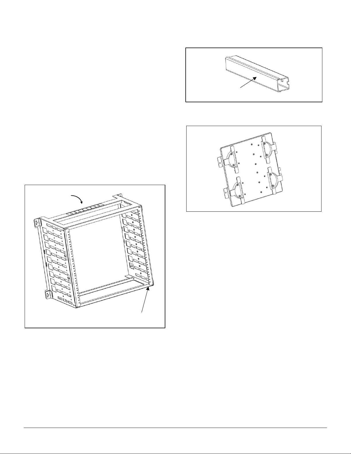
The WR-10U (Figure 3) features welded steel, carrier-
class construction. The front of the frame provides two
vertical rails with standard threaded hole spacing for up to
ten rack units. Eight pairs of threaded grounding holes
and pre-installed screws are provided on the rear
crossbar for attachment of ground lugs. One pair of holes
supports grounding of the WR-10U itself and the other
seven pairs of holes support ground connections from
installed equipment. The unpainted grounding area
provides metal-to-metal contact with ground lug surfaces.
Figure 3. WR-10U Features
Cable Guides
Optional cable guides with removable covers (Figure 4)
can be attached to either side of the WR-10U frame. Up
to ten cable guides can be installed per side.
Side Plate with Take-up Reels
An optional side plate, Model SPL-4H (Figure 5), provides
two adjustable cable take-up reels. The reels are sized to
maintain proper bend radius in fiber applications. The
metal plate can be attached to either side of the WR-10U
frame using the included hardware.
Figure 4. Cable Guide
4. INSTALLATION
The WR-10U shipping carton contains the following:
•Pre-assembled mounting frame
•Six (6) #12 x 1” slotted hex screws, self-tapping
•Product documentation
•Drill template
Installation steps are described in detail below.
A. Mounting frame
Select an appropriate location on a wall or backboard
to install the mounting frame. Choose a mounting
surface and hardware that can support the combined
weight of the mounting assembly and equipment that
is to be installed. Mounting to a 3/4” thick backboard
with #12 x 1” screws is recommended. Maximum
weight holding capacity of the WR-10U is 200 lbs.
Determine the desired orientation of the ground lugs.
The symmetrical design of the WR-10U frame allows it
to be installed with the grounding holes facing upward
or downward.
Tape the drill template to the wall ensuring it is level.
The drill template provides information for multiple wall
Threaded
grounding holes
Standard threaded hole
spacing for up to 10 rack units
Slide on/off cover
Figure 5. Model SPL-4H Side Plate
Figure 6. Model SPL-4H Side Plate
001-01-000083 Rev. 001 Page 3 of 5
mounted racks. Be sure to use the hole symbol Ⓑ.
Drill six (6) 3/16” pilot holes. These holes mate with
the mounting brackets located at the rear corners of
the frame. The frame will be fastened with two screws
in each of the upper brackets and one screw in each
of the lower brackets, as shown in Figure 6.
Before attempting to fasten the mounting frame to the
wall, insert a screw into the top pilot hole on either the
left or right side. Partially thread the screw into the
hole, leaving the screw head approximately 1/4” from
the surface.
Hold the mounting frame against the wall while resting
the cutout of the bracket on the installed screw. Align
the other five mounting holes and install a screw in
each hole. Tighten all six (6) screws securely.
B. Frame grounding
Locate the eight (8) pairs of pre-installed grounding
screws with lock washers on the crossbar of the
frame. The grounding screws are 10-32 x 3/8” on 5/8”
centers.
Install a dual ground lug (customer provided) with
holes on 5/8” centers beneath the included screws
and washers on one pair of grounding holes. Tighten
the screws to fasten the lug to the mounting frame.
The example in Figure 7 illustrates the frame
positioned with grounding screws facing downward.
Connect a ground wire of appropriate gauge to the
ground lug and attach the other end of the wire to a
bonded ground point, per local procedures for network
equipment.
Figure 7. Frame grounding example
C. Equipment Installation
Install rack equipment with 19” hole spacing by
carefully sliding the chassis through the front of the
WR-10U and aligning chassis mounting ears with the
threaded holes in the rails of the WR-10U frame.
Insert and tighten #12-24 machine screws (customer
provided) on each side of the chassis. An example of
a fully populated wall rack is shown in Figure 2.
Attach ground lugs associated with each equipment
chassis to the threaded ground holes on the WR-10U
crossbar as needed.
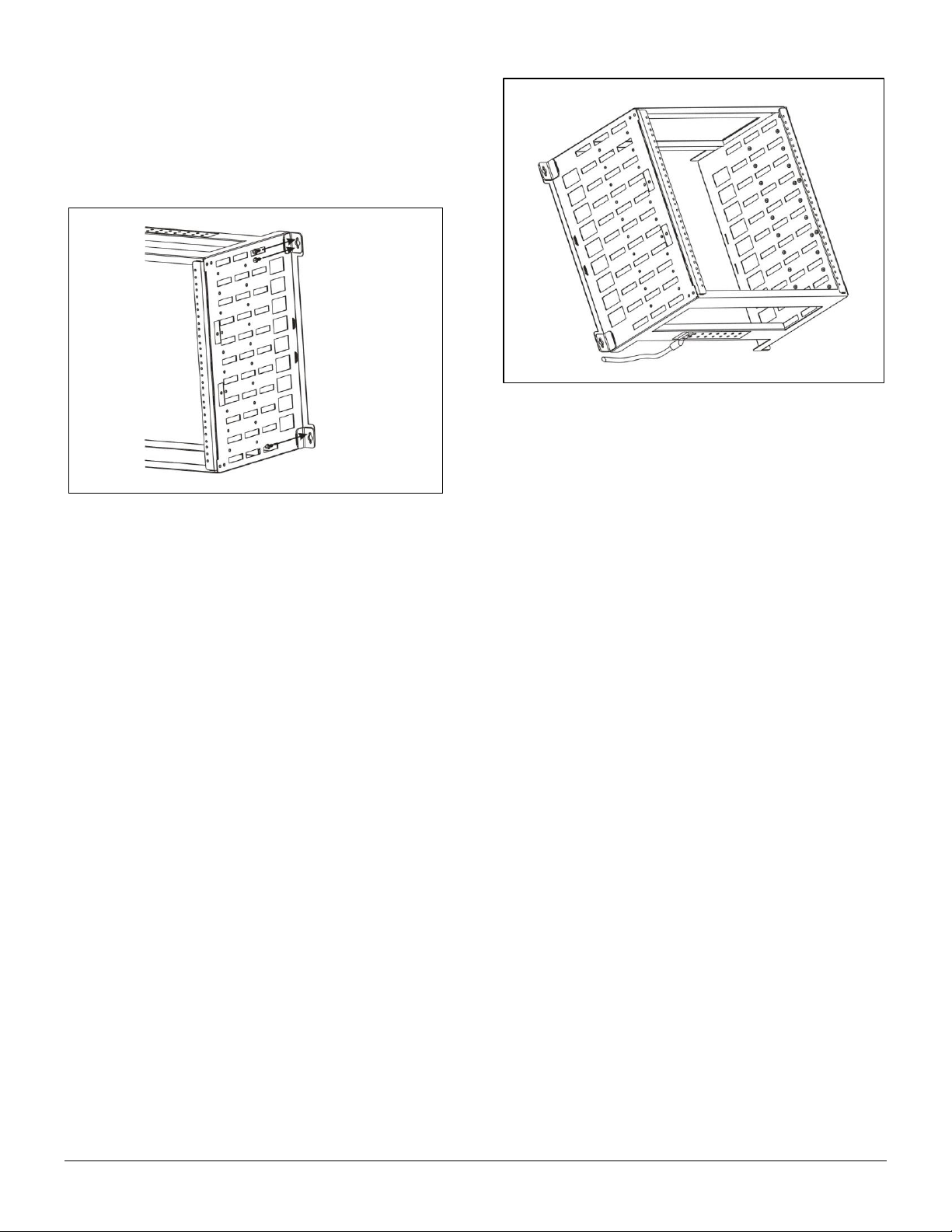
D. Optional Cable Guide Installation
To install a cable guide to the side of the mounting,
first remove the sliding cover from the cable guide.
Insert two of the #10-32 x 3/8” screws (included in
CG-5 package) through the cable guide and into the
threaded holes on the side of the WR-10U frame
(Figure 8).
Groom cabling from the front of the chassis to the wall
through the cable guide on the side of the WR-10U, as
shown in Figure 9, and replace the sliding cover.
Figure 6. Mounting screw locations
Figure 7. Mounting screw locations
001-01-000083 Rev. 001 Page 4 of 5
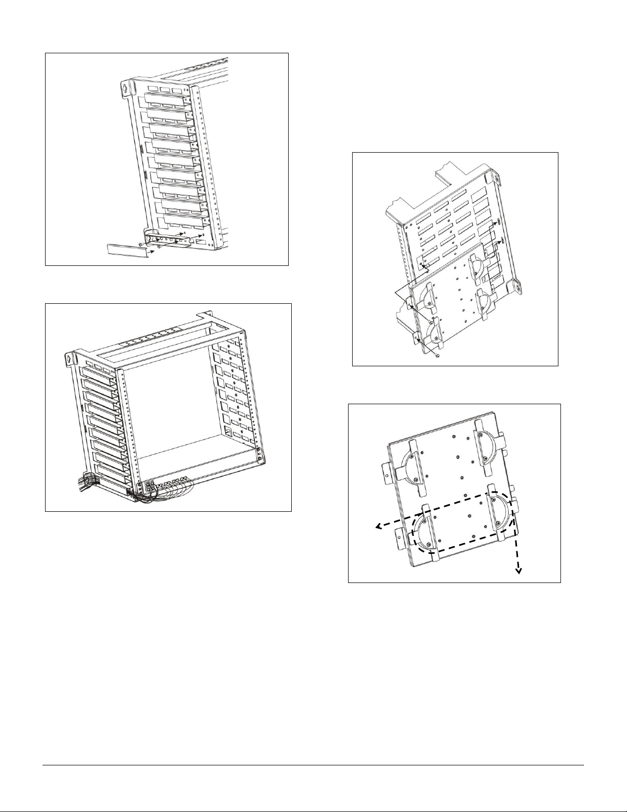
E. Optional Side Plate Installation
Threaded holes on both sides of the WR-10U frame allow
an optional side plate (Model SPL-4H) or additional cable
guides to be installed to expand cable management. The
SPL-4H provides two split and adjustable take-up reels,
as illustrated in Figure 5.
To install and use the SPL-4H side plate, refer to Figure
10 and the steps below.
Slide the two narrower tabs at the edge of the SPL-4H
into the openings on the side of the WR-10U, toward
the rear of the mounting.
Align the wide tabs at the front edge of the SPL-4H
with the threaded holes on the side of the WR-10U
frame. Use the two (2) included #10-32 x 3/8” screws
to securely fasten the side plate to the frame.
Carefully wrap cables around the take-up reels to
reduce slack as needed. Example routing is shown in
Figure 11. Alternate mounting holes are included on
the side plate for repositioning the half-reels, if desired.
5. TESTING AND TROUBLESHOOTING
Each piece of equipment installed in the WR-10U should
be tested according the manufacturer’s instructions.
Figure 8. Cable guide installation
Figure 9. Cable guide application
Figure 10. SPL-4H installation
Figure 11. Cable take-up reel routing

001-01-000083 Rev. 001 Page 5 of 5
6. CUSTOMER SERVICE
If technical or customer assistance is required, please
contact Enginuity at the following:
Customer Service
1-800-980-3266
Technical Support
1-800-841-1005
Enginuity Communications
3545 Stern Avenue
St. Charles, Illinois 60174
www.enginuitycom.com
7. WARRANTY & REPAIRS
Warranty
Enginuity warrants this product for one (1) year from date
of purchase. Any attempt to repair or modify the
equipment by anyone other than an authorized Enginuity
representative will void the warranty.
This limited warranty does not cover any losses or
damages resulting from shipment to or from the
This limited warranty does not cover any losses or
damages resulting from shipment to or from the
customer, or from improper installation, abuse,
modifications, or unauthorized repair by other than
Enginuity personnel.
Repair and Return
Enginuity equipment will be repaired or replaced without
cost during the warranty period if the product is defective
for any reason other than abuse, improper use, or
improper installation. Before returning defective
equipment, first request a Return Material Authorization
(RMA) number from Enginuity. Once an RMA number is
obtained, return the unit, freight prepaid, along with a brief
description of the problem, to:
Enginuity Communications
3545 Stern Avenue
St. Charles, Illinois 60174
ATTN: Repair & Return Dept.
Replacements will be shipped in the fastest manner
consistent with the urgency of the situation. Repair or
replacement of faulty equipment beyond the warranty
period is available for a nominal charge.
8. SPECIFICATIONS
Mounting Frame
Part Number
WR-10U
Description
OnSite™ 19”/10U wall rack
Dimensions (H x W x D)
19.25 x 22.7 x 12.6 inches
Weight
14.0 pounds
Capacity
10 rack units, total installed equipment weight not to exceed 200 lbs.
Operating Temperature
0 to 50C
Standards Compliance
Meets applicable Telcordia NEBS requirements, including Zone 4 seismic.
Optional Side Plate
Part Number
SPL-4H
Description
Side plate for wall rack with (2) adjustable take-up reels
Dimensions (H x W x D)
10.5 x 11.3 x 1.3 inches
Weight
2.5 pounds
Additional Cable Guides
Part Number
CG-5
Description
Pack of (5) cable guides for wall rack
Dimensions (H x W x D)
1.0 x 1.3 x 7.8 inches (each)
Weight
2.0 ounces (each)
Table of contents
Other Enginuity Enclosure manuals


