EnOcean TCM 515 User manual

USER MANUAL
TCM 515 –ENOCEAN TRANSCEIVER GATEWAY MODULE
© 2019 EnOcean | www.enocean.com F-710-017, V1.0 TCM 515 User Manual | v1.13 | August 2019 | Page 1/86
Patent protected:
WO98/36395, DE 100 25 561, DE 101 50 128,
WO 2004/051591, DE 103 01 678 A1, DE 10309334,
WO 04/109236, WO 05/096482, WO 02/095707,
US 6,747,573, US 7,019,241
Observe precautions! Electrostatic sensitive devices!
TCM 515 EnOcean Transceiver Gateway Module
08.08.2019

USER MANUAL
TCM 515 –ENOCEAN TRANSCEIVER GATEWAY MODULE
© 2019 EnOcean | www.enocean.com F-710-017, V1.0 TCM 515 User Manual | v1.13 | August 2019 | Page 2/86
REVISION HISTORY
The following major modifications and improvements have been made to this document:
Version
Author
Reviewer
Date
Major Changes
1.0
MKA
MK, CB
12.05.2017
First public release
1.1
MKA
MKA
22.05.2017
Added detailed antenna information
1.2
MKA
MH, MK
22.06.2017
Added receiver class due to RED requirement
1.3
OS
MKA
08.08.2017
Added FCC grant and regulatory information
for FCC and ISED; Added maximum input
power
1.4
MKA
MKA
31.08.2017
Added Tape & Reel specification
1.5
MKA
MKA
19.09.2017
Added detailed description of filtering function-
ality
1.6
MKA
MKA
25.10.2017
Added maximum number of filters
1.7
MKA
MKA
10.01.2018
Extensive update for production version.
Added detailed description of telegram pro-
cessing, security operations and noise filter-
ing.
1.8
MKA
MKA
30.01.2018
Added product revision history
Added maximum input power and RSSI accu-
racy. Added current during start-up.
1.9
MKA
MKA
30.04.2018
Added DA-7 to product history
1.10
MKA
MKA
31.07.2018
Added DB-8 to product history, extended de-
scription of ESP3 interface, telegram filtering
and BaseID functionality
1.11
MKA
MKA
08.01.2019
Added application info for SAW circuit
1.12
MKA
MKA
05.02.2019
Added note regarding test points and regard-
ing RLC storage.
1.13
MKA
MKA
08.08.2019
Update with new features in product version
DB-09
Published by EnOcean GmbH, Kolpingring 18a, 82041 Oberhaching, Germany
www.enocean.com, info@enocean.com, phone +49 (89) 6734 6890
© EnOcean GmbH, All Rights Reserved

USER MANUAL
TCM 515 –ENOCEAN TRANSCEIVER GATEWAY MODULE
© 2019 EnOcean | www.enocean.com F-710-017, V1.0 TCM 515 User Manual | v1.13 | August 2019 | Page 3/86
Disclaimer
This user manual describes the type of component and shall not be considered as assured
characteristics. No responsibility is assumed for possible omissions or inaccuracies. Circuitry
and specifications are subject to change without notice. For the latest product specifications,
refer to the EnOcean website: http://www.enocean.com.
As far as patents or other rights of third parties are concerned, liability is only assumed for
modules, not for the described applications, processes and circuits.
EnOcean does not assume responsibility for use of modules described and limits its liability
to the replacement of modules determined to be defective due to workmanship. Devices or
systems containing RF components must meet the essential requirements of the local legal
authorities.
The modules must not be used in any relation with equipment that supports, directly or
indirectly, human health or life or with applications that can result in danger for people,
animals or real value.
Components of the modules are considered and should be disposed of as hazardous waste.
Local government regulations are to be observed.
Packing: Please use the recycling operators known to you.

USER MANUAL
TCM 515 –ENOCEAN TRANSCEIVER GATEWAY MODULE
© 2019 EnOcean | www.enocean.com F-710-017, V1.0 TCM 515 User Manual | v1.13 | August 2019 | Page 4/86
TABLE OF CONTENT
1General description........................................................................................ 7
1.1 Basic functionality ......................................................................................... 7
1.2 Technical data............................................................................................... 8
1.3 Physical dimensions.......................................................................................9
1.4 Environmental conditions ...............................................................................9
1.5 Packaging information.................................................................................... 9
1.6 Ordering information......................................................................................9
2Functional information ................................................................................. 10
2.1 High level functionality................................................................................. 10
2.2 Functional modes ........................................................................................ 11
2.3 Device Interface.......................................................................................... 12
2.3.1 Pin-out ............................................................................................... 12
2.4 Power supply .............................................................................................. 13
2.5 Antenna ..................................................................................................... 13
2.6 UART interface ............................................................................................ 13
2.7 Reset ......................................................................................................... 14
2.8 Test Interface (TP1, TP2, TP3) ...................................................................... 14
3Power-up and system initialization................................................................. 15
3.1 Start-up timing ........................................................................................... 15
3.2 User-configurable delay................................................................................ 15
4Telegram reception...................................................................................... 16
4.1 RX maturity time......................................................................................... 17
4.2 Telegram filtering ........................................................................................ 18
4.2.1 Filter types ......................................................................................... 18
4.2.2 Filter definition .................................................................................... 19
4.2.3 Filter enabling ..................................................................................... 20
4.2.4 Filter reading....................................................................................... 21
4.2.5 Filter deletion ...................................................................................... 22
4.2.6 Filter examples.................................................................................... 23
4.2.6.1 Forwarding (Receiver) filter examples.................................................. 23
4.2.6.2 Repeater filter examples .................................................................... 24
5Telegram transmission ................................................................................. 25
5.1 Transmission flow........................................................................................ 25
5.2 Subtelegram Timing .................................................................................... 26
5.3 TX Maturity Time......................................................................................... 27
5.4 Address types ............................................................................................. 27
5.4.1 EURID ................................................................................................ 28
5.4.2 Base ID .............................................................................................. 28
5.4.2.1 Base ID usage .................................................................................. 29
5.4.3 Broadcast ID ....................................................................................... 29
5.5 Duty Cycle Limit.......................................................................................... 30

USER MANUAL
TCM 515 –ENOCEAN TRANSCEIVER GATEWAY MODULE
© 2019 EnOcean | www.enocean.com F-710-017, V1.0 TCM 515 User Manual | v1.13 | August 2019 | Page 5/86
5.5.1 Determining available transmission time................................................. 31
6Telegram repeating ..................................................................................... 32
6.1 Configuration of telegram repeating............................................................... 33
7Security functionality ................................................................................... 34
7.1 Basic concepts ............................................................................................ 34
7.1.1 Telegram encryption ............................................................................ 35
7.1.2 Telegram authentication ....................................................................... 35
7.1.3 Dynamic security key modification ......................................................... 37
7.2 TCM 515 implementation specifics ................................................................. 38
7.2.1 High level architecture.......................................................................... 38
7.2.2 High level execution flow ...................................................................... 39
7.2.3 Secure link table.................................................................................. 40
7.2.3.1 Secure link table parameters .............................................................. 41
7.2.4 Secure EEP support.............................................................................. 42
7.3 Supported security features.......................................................................... 43
7.3.1 Telegram encryption and decryption....................................................... 43
7.3.2 Telegram authentication ....................................................................... 43
7.3.3 Rolling codes....................................................................................... 44
7.3.3.1 Explicit versus implicit rolling code ...................................................... 44
7.3.3.2 RLC roll-over .................................................................................... 45
7.3.3.1 RLC backup ...................................................................................... 46
7.4 Teach-in of secure devices............................................................................ 47
7.4.1 Security parameters............................................................................. 47
7.4.1.1 Security key ..................................................................................... 48
7.4.1.2 Rolling code ..................................................................................... 48
7.4.1.3 Security level format (SLF)................................................................. 48
7.4.2 Teach-in of secure devices with teach-in telegram ................................... 49
7.4.2.1 Learn mode...................................................................................... 50
7.4.2.2 Handling of teach-in telegram when not in teach-in mode ...................... 51
7.4.3 Transmission of a secure teach-in telegram............................................. 51
7.4.4 Teach-in of secure devices using ESP3 ................................................... 52
7.5 Reporting of security-related events .............................................................. 54
8Low power sleep mode................................................................................. 55
9ESP3 interface ............................................................................................ 56
9.1 ESP3 physical interface ................................................................................ 56
9.2 ESP3 Packet Structure ................................................................................. 57
9.3 Supported ESP3 commands .......................................................................... 58
9.4 Persistent versus not persistent configuration settings ..................................... 59
10 Remote Management ................................................................................... 60
11 Device Integration....................................................................................... 61
11.1 Recommended PCB Footprint ................................................................... 61
11.2 Device outline ........................................................................................ 62
11.3 Soldering information.............................................................................. 63
11.4 Packaging information............................................................................. 64
11.5 Layout recommendations......................................................................... 65
11.6 Power supply requirements...................................................................... 66
11.7 Using an SAW Filter with TCM 515 (868 MHz version only) .......................... 66

USER MANUAL
TCM 515 –ENOCEAN TRANSCEIVER GATEWAY MODULE
© 2019 EnOcean | www.enocean.com F-710-017, V1.0 TCM 515 User Manual | v1.13 | August 2019 | Page 6/86
11.8 Low noise design considerations ............................................................... 67
11.9 Suggested Reset circuit ........................................................................... 68
11.10 Identifying the TCM 515 product revision................................................ 69
12 Antenna options .......................................................................................... 70
12.1 Antenna options for 868 MHz (European Union).......................................... 70
12.1.1 Whip antenna...................................................................................... 71
12.2 Antenna options for 902 MHz (US / Canada) .............................................. 72
12.2.1 Whip antenna...................................................................................... 72
12.2.2 Helical antenna.................................................................................... 72
12.2.3 Chip antenna (Supplier: Mitsubishi Material, Type AM11DP-ST01T)............ 73
12.2.4 Dipole antenna (ANT-916-CW-HWR-RPS)................................................ 74
13 Application information ................................................................................ 75
13.1 Transmission range................................................................................. 75
13.2 Maximum input power............................................................................. 76
13.3 RSSI reporting ....................................................................................... 76
14 Regulatory information................................................................................. 77
14.1 RED (European Union) ............................................................................ 77
14.1.1 RED Attestation of Conformity for TCM 515 ............................................. 78
14.2 FCC (United States) ................................................................................ 79
14.2.1 FCC Grant Of Equipment Authorization ................................................... 79
14.2.2 FCC Usage Conditions .......................................................................... 80
14.2.3 OEM Requirements .............................................................................. 81
14.2.4 Module Activation ................................................................................ 82
14.3 ISED (former Industry Canada) Certification .............................................. 83
14.3.1 ISED Technical Acceptance Certificate .................................................... 83
14.3.2 ISED Usage Conditions ......................................................................... 84
14.4 Repeater Function (FCC/IC) ..................................................................... 85
15 Product history............................................................................................ 86

USER MANUAL
TCM 515 –ENOCEAN TRANSCEIVER GATEWAY MODULE
© 2019 EnOcean | www.enocean.com F-710-017, V1.0 TCM 515 User Manual | v1.13 | August 2019 | Page 7/86
1General description
1.1 Basic functionality
TCM515 is an addition to the existing TCM 300 / 310 / 320 transceiver module family con-
sisting of the following products:
◼TCM 515
868.3 MHz ASK, EnOcean Radio Protocol version 1, main market Europe
◼TCM 515U
902.875 MHz FSK, EnOcean Radio Protocol version 2, main market US and Canda
The term “TCM 515” in this document refers to all members of the TCM 515 family unless
noted differently.
TCM 515 products are limited to OEM installation ONLY.
TCM 515 is optimized for application requiring smallest possible size and integrated security
handling such as line-powered actuators or controllers.
For applications requiring highest radio performance - such as gateways or access points
covering larger areas –consider using TCM 310 which provides the highest possible sensitiv-
ity and noise immunity.
TCM 515 provides a transparent radio link between EnOcean radio devices and an external
host connected via UART interface using the standardized EnOcean Serial Protocol V3 (ESP3)
communication protocol.
TCM 515 receives and transmits radio telegrams based on a 50 Ohm or whip antenna con-
nected to the host PCB. It forwards received radio telegrams to an external host processor
or host PC via the ESP3 interface. Messages received from an external host via the ESP3
interface will be transmitted by TCM 515 as EnOcean radio telegrams according to the chosen
frequency.
TCM 515 is implemented as 31 pin reflow-solderable module with optimized form factor for
size constrained applications. It is not pin compatible with existing TCM 310 products. Figure
1 below shows TCM 515.
Figure 1 –TCM 515 outline

USER MANUAL
TCM 515 –ENOCEAN TRANSCEIVER GATEWAY MODULE
© 2019 EnOcean | www.enocean.com F-710-017, V1.0 TCM 515 User Manual | v1.13 | August 2019 | Page 8/86
1.2 Technical data
Antenna
50 Ohm whip antenna (connected at host board)
Supported Radio Frequencies
TCM 515: 868.3 MHz ASK
TCM 515U: 902.875 MHz FSK
Data Rate
125 kbps
Receiver Sensitivity (1)
TCM 515: 868.3 MHz ASK: -92 dBm
TCM 515U: 902.875 MHz FSK: -98 dBm
Maximum Input Power (1)
-23 dBm
Receiver Blocking Performance
Class 2 according to EN 300 220-1
Radiated RF Immunity
3 V / m according to EN 301 489-3
Transmit Power
TCM 515: 868.3 MHz ASK: +10 dBm
TCM 515U: 902.875 MHz FSK: +1 dBm
Supply Voltage (min / max / typ)
2.0 V / 3.6 V / 3.3 V
Supply Current (at 2.0V)
25 mA
Supply Current Sleep Mode (at 2.0V / 25°C)
0.05 mA
Power-up to Ready State Timing (2)
50 ms
Ready State to RX State Delay (2)
200 ms (adjustable via ESP3)
Supply Current between Power-up and RX
12 mA
TX to RX switching time (3)
< 1 ms
Serial Host Interface
UART according to ESP3 Standard (TURBO option)
Note 1: Sensitivity and Maximum Input Power figures are based on 0.1% telegram error rate for the combination of
3 received sub-telegrams measured at 25°C
Note 2: TCM 515 up to revision DB-08 requires approximately 50 ms in total for start-up after power up. Starting
from revision DB-09, this time is reduced to approximately 15 ms in total.
During start-up, TCM 515 waits for a configurable additional delay period before starting RX mode to allow for power
supply stabilization. The default delay period is 200 ms; this is adjustable via ESP3 command (see chapter 3.2)
Note 3: TX to RX switch over time is measured from the transmission of the last bit (end of frame) of a radio frame
until the receiver is ready to receive the first bit (preamble) of a radio frame

USER MANUAL
TCM 515 –ENOCEAN TRANSCEIVER GATEWAY MODULE
© 2019 EnOcean | www.enocean.com F-710-017, V1.0 TCM 515 User Manual | v1.13 | August 2019 | Page 9/86
1.3 Physical dimensions
Module Dimensions
19.0 mm x 14.7 mm x 3.0 mm (all +- 0.3 mm)
Module Weight
1 g
1.4 Environmental conditions
Operating Temperature
-40°C ... 85°C
Storage Temperature
-40°C ... 85°C
Humidity
0% to 95% r.h. (non-condensing)
1.5 Packaging information
Packaging Unit / Method 250 units / Tape and reel
1.6 Ordering information
Type
Ordering Code
TCM 515
TCM 515U
S3003-K515
S3053-K515

USER MANUAL
TCM 515 –ENOCEAN TRANSCEIVER GATEWAY MODULE
© 2019 EnOcean | www.enocean.com F-710-017, V1.0 TCM 515 User Manual | v1.13 | August 2019 | Page 10/86
2Functional information
2.1 High level functionality
TCM 515 is a fully integrated radio transceiver family which enables communication with
other devices implementing the EnOcean Radio Protocol (ERP).
TCM 515 is used to exchange (send and / or receive) radio telegrams with external sensors,
switches or actuators.
TCM 515 is connected to an external host which for instance could be a microprocessor, a
controller or a gateway via the EnOcean Serial Protocol v3 (ESP3) interface.
ESP3 commands are listed within this document for information purposes only; for details
about ESP3 commands refer to the ESP3 specification available from
https://www.enocean.com/esp3
Figure 2 below shows the integration of TCM 515 into a typical system environment.
Figure 2 –TCM 515 system environment
USER MANUAL
TCM 515 –ENOCEAN TRANSCEIVER GATEWAY MODULE
© 2019 EnOcean | www.enocean.com F-710-017, V1.0 TCM 515 User Manual | v1.13 | August 2019 | Page 11/86
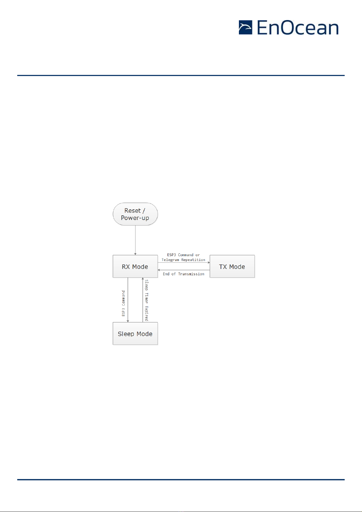
2.2 Functional modes
TCM 515 implements the following functional modes:
◼Power-up and system initialization
◼Telegram reception (including security processing, filtering and repeating if required)
◼Telegram transmission (including security processing if required)
◼Low Power Sleep
The transition between these functional modes is shown in Figure 3 below
Figure 3 –TCM 515 functional modes
Subsequent chapters describe these functional modes in more detail.
USER MANUAL
TCM 515 –ENOCEAN TRANSCEIVER GATEWAY MODULE
© 2019 EnOcean | www.enocean.com F-710-017, V1.0 TCM 515 User Manual | v1.13 | August 2019 | Page 12/86
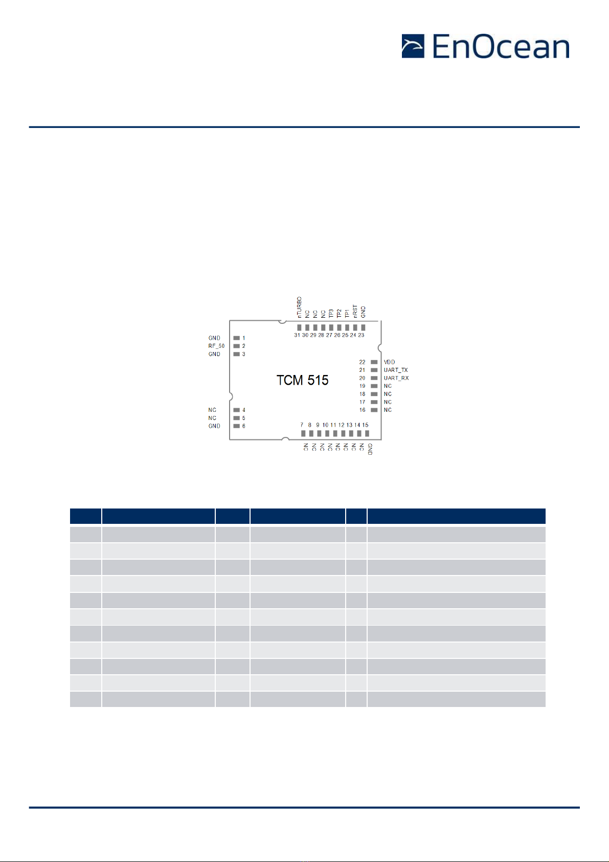
2.3 Device Interface
TCM 515 implements a 31 pin reflow-solderable interface. Solder mask data is available on
request from EnOcean.
2.3.1 Pin-out
The pin assignment (as seen from the top of the device) is shown in Figure 4 below. Solder
mask and mechanical data is available from EnOcean.
Figure 4 –TCM 515 device interface
Table 1 below summarizes the signal assignment.
PIN
NAME
PIN
NAME
PIN
NAME
1
GND
12
NC
23
GND
2
RF_50 (50Ω antenna)
13
NC
24
nRST (Reset, active low)
3
GND
14
NC
25
TP1 (Test Interface)
4
NC
15
GND
26
TP2 (Test Interface)
5
NC
16
NC
27
TP3 (Test Interface)
6
GND
17
NC
28
NC
7
NC
18
NC
29
NC
8
NC
19
NC
30
NC
9
NC
20
UART_RX (Input)
31
nTURBO (UART speed, active low)
10
NC
21
UART_TX (Output)
11
NC
22
VDD
Table 1 - TCM 515 pin assignment
Signals marked with “NC” are reserved for production test and future device variants and
must not be connected in the design.

USER MANUAL
TCM 515 –ENOCEAN TRANSCEIVER GATEWAY MODULE
© 2019 EnOcean | www.enocean.com F-710-017, V1.0 TCM 515 User Manual | v1.13 | August 2019 | Page 13/86
2.4 Power supply
TCM 515 is supplied by the VDD and GND Pins and supports a supply voltage range from 2.0
V to 3.6 V. For best radio performance it is very important to minimize noise on the supply
voltage lines. Please see chapter 11.5 and 11.6.
2.5 Antenna
TCM 515 receives and transmits data based on a 50Ω whip antenna connected to its RF_50
input (Pin 2). Please see chapter 12.
2.6 UART interface
TCM 515 communicates with the external host using the standard ESP3 serial (UART) inter-
face based on the signals UART_TX (Pin 21, direction from TCM 515 to external host) and
UART_RX (Pin 20, direction from external host to TCM 515).
The default interface speed of the ESP3 interface is 57600 bit per second and data is trans-
mitted using 8 data bits, 1 STOP bit and no parity (8N1).
It is possible to select faster communication speeds during operation using the ESP3
CO_SET_BAUDRATE command (see chapter 9.1). The following interface speeds are sup-
ported by TCM 515:
◼57600 bit per second
◼460800 bit per second
Additionally, it is possible to change the default ESP3 interface speed at power up from
57.600 Bit per second to 460.800 Bit per second by connecting the nTURBO input (Pin 31,
active low) to Ground.
Subsequent modification of the interface speed during operation using the CO_SET_BAU-
DRATE command is always possible irrespective of the state of the TURBO input pin. Care
should be taken not to select a UART interface speed which cannot be supported by the
connected host processor as this would prevent subsequent communication.

USER MANUAL
TCM 515 –ENOCEAN TRANSCEIVER GATEWAY MODULE
© 2019 EnOcean | www.enocean.com F-710-017, V1.0 TCM 515 User Manual | v1.13 | August 2019 | Page 14/86
2.7 Reset
TCM 515 can be reset by pulling the nRST pin (Pin 24, active low) to Ground. Please see
chapter 11.9 for reset circuit recommendations.
2.8 Test Interface (TP1, TP2, TP3)
TCM 515 provides a test interface (TP1, TP2 and TP3). The intended use of this interface is
for analysis and debugging of customer products by EnOcean. It is strongly recommended
that customer PCB design provides the ability to connect to this interface.
USER MANUAL
TCM 515 –ENOCEAN TRANSCEIVER GATEWAY MODULE
© 2019 EnOcean | www.enocean.com F-710-017, V1.0 TCM 515 User Manual | v1.13 | August 2019 | Page 15/86
3Power-up and system initialization
After power-up, TCM 515 executes the following functions:
◼Initialization of the MCU
◼Wait for pre-configured delay (default 200 ms)
◼Initialization of the radio
After that, TCM 515 is in ready for operation and will transition to receive mode.
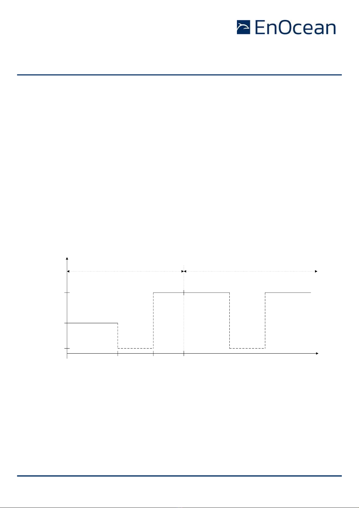
3.1 Start-up timing
For TCM 515 devices up to device revision DB-08, the typical start-up time is 50 ms (exclud-
ing the configured additional delay).
For TCM 515 devices starting with device revision DB-09, start-up time and power consump-
tion has been reduced resulting in a shortened start-up sequence shown in Figure 5 below.
0 ms 10 ms
50 uA
7.5 mA
10 ms + DELAY
DELAY
MCU INIT
25 mA RADIO INIT
15 ms + DELAY Time
Current
RUNNING (RX or TX)
SLEEP
RUNNING (RX or TX)
Start-up and device initialization Device operation
Figure 5 –TCM 515 start-up sequence
3.2 User-configurable delay
TCM 515 provides the option for a configurable additional delay between start-up and oper-
ation to allow the external power supply to stabilize before the device starts the radio. The
factory-programmed default value of this delay is 200 ms. It can be configured as persistent
parameter (maintained after power down) using the ESP3 command CO_WR_STARTUP_DE-
LAY.

USER MANUAL
TCM 515 –ENOCEAN TRANSCEIVER GATEWAY MODULE
© 2019 EnOcean | www.enocean.com F-710-017, V1.0 TCM 515 User Manual | v1.13 | August 2019 | Page 16/86
4Telegram reception
After start-up, TCM 515 will enter receive mode. For each received telegram, TCM 515 per-
forms the following functions:
◼RX Frame processing
Received data bitstream is processed (detection and removal of preamble, start of
frame, end of frame and redundant bits, CRC check, subtelegram merge) and format-
ted as EnOcean radio telegrams
◼Repeater handling
Received telegrams are checked if they should be repeated based on the repeater
mode configured at TCM 515 (L1 Repeater, L2 Repeater, Selective Repeater) and the
repeater information reported as part of the radio telegram. If the received telegram
should be repeated then it will be inserted into the transmission queue. See chapter
6 for details on the repeater functionality.
◼Telegram filtering
Received telegrams can be classified according to user-defined characteristics so that
only telegrams matching these characteristics will be processed and forwarded to the
external host via the ESP3 interface. See chapter 4.2 for details.
◼Security processing
Telegrams from senders using high security mode can be automatically decrypted and
authenticated according to their security parameters stored in the inbound secure link
table. See chapter 7 for details.
◼ESP3 formatting and telegram forwarding
Processed telegrams will be formatted as ESP3 message and forwarded to the external
host via the ESP3 interface. See chapter 9 for details.
Figure 6 below shows the processing flow for received telegrams.
L1 / L2 /
Selective
Repeating
Repeater
Filter List
RX Frame
Processing
TX Frame
Processing
Telegram
Filtering
Host
Filter List
ESP3
Formatting
RX / TX
Switch
Antenna
External Host
Security
Processing
Inbound
Link Table
Figure 6 –Telegram Reception Flow

USER MANUAL
TCM 515 –ENOCEAN TRANSCEIVER GATEWAY MODULE
© 2019 EnOcean | www.enocean.com F-710-017, V1.0 TCM 515 User Manual | v1.13 | August 2019 | Page 17/86
4.1 RX maturity time
The reception (RX) maturity time defines the longest possible interval between the reception
of the first subtelegram and the reception of the last subtelegram belonging to the same
telegram.
Considering the worst case of a telegram received after two levels of repeating, the RX ma-
turity time is always < 100 ms (39 ms + 29 ms + 29 ms) as shown in Table 9.
TCM 515 can be configured to wait for the RX maturity time (100 ms) after reception of a
subtelegram in order to determine the number of received subtelegrams. TCM 515 will in
that case report the actual number of received subtelegrams to the external host.
Alternatively, TCM 515 can be configured to immediately forward a received subtelegram to
the host and discard subsequent identical subtelegrams. This provides the lowest latency and
is the default operation mode for TCM 515.
The selection between these two options is done using the CO_WR_WAIT_MATURITY com-
mand as shown in Table 2 below.
Group
Offset
Size
Field
Value hex
Description
-
0
1
Sync. Byte
0x55
Header
1
2
Data Length
0x0002
2 bytes
3
1
Optional Length
0x00
0 byte
4
1
Packet Type
0x05
COMMON_COMMAND = 5
-
5
1
CRC8H
0xnn
Data
6
1
COMMAND Code
0x10
CO_WR_WAIT_MATURITY = 16
7
1
Wait End Maturity
0xnn
0x00: Received telegrams are forwarded
to the external host immediately
0x01: Received telegrams are forwarded
to the external host after the maturity
time elapsed
-
8
1
CRC8D
0xnn
Table 2 –CO_WR_MATURITY

USER MANUAL
TCM 515 –ENOCEAN TRANSCEIVER GATEWAY MODULE
© 2019 EnOcean | www.enocean.com F-710-017, V1.0 TCM 515 User Manual | v1.13 | August 2019 | Page 18/86
4.2 Telegram filtering
By default, TCM 515 will forward all valid telegrams received by it (including such that are
addressed to a different receiver) to the host via its ESP3 interface.
Filtering allows to setup TCM 515 to forward only specific telegrams (e.g. only such that are
addressed to it) to the external host. Only radio telegrams that match specific user-defined
parameters will be forwarded to the external host (selective forwarding) or repeated (selec-
tive repeating).
Filtering therefore can be used to limit the amount of telegram processing required at the
external host or to optimize the available radio bandwidth.
4.2.1 Filter types
Telegram filtering is the process by which only radio telegrams that match specific user-
defined parameters will be forwarded to the external host (selective forwarding) or repeated
(selective repeating). The following parameters can be used as filter condition:
◼Source ID
Only radio telegrams originating from a specific sender (identified by its EnOcean Uni-
versal Radio ID = EURID) will be processed.
This filter type can be used for instance in actuators which only accept input from
devices (e.g. switches) that have been learned in.
◼Destination ID
Only radio telegrams addressed to a specific receiver (as identified by its EURID) will
be processed. This filter type can be used by a receiver to accept only radio telegrams
intended for itself.
Note that the Broadcast ID (0xFFFF:FFFF) cannot be used as destination ID filter.
◼Telegram Type (RORG)
Only radio telegrams of a specific type (RPS, 1BS, 4BS or VLD) will be processed. This
filter type can be used for instance if an actuator should react only on switch (RPS)
telegrams.
◼Received signal strength (RSSI)
Only radio telegrams above or below a specific signal strength will be processed.
The first case –above - can for instance be used during learn-in if an actuator should
only accept teach-in telegrams from devices close to the receiver.
The second case –below - can be used in repeaters where only weak signals (with
low RSSI) should be repeated in order to limit radio congestion.

USER MANUAL
TCM 515 –ENOCEAN TRANSCEIVER GATEWAY MODULE
© 2019 EnOcean | www.enocean.com F-710-017, V1.0 TCM 515 User Manual | v1.13 | August 2019 | Page 19/86
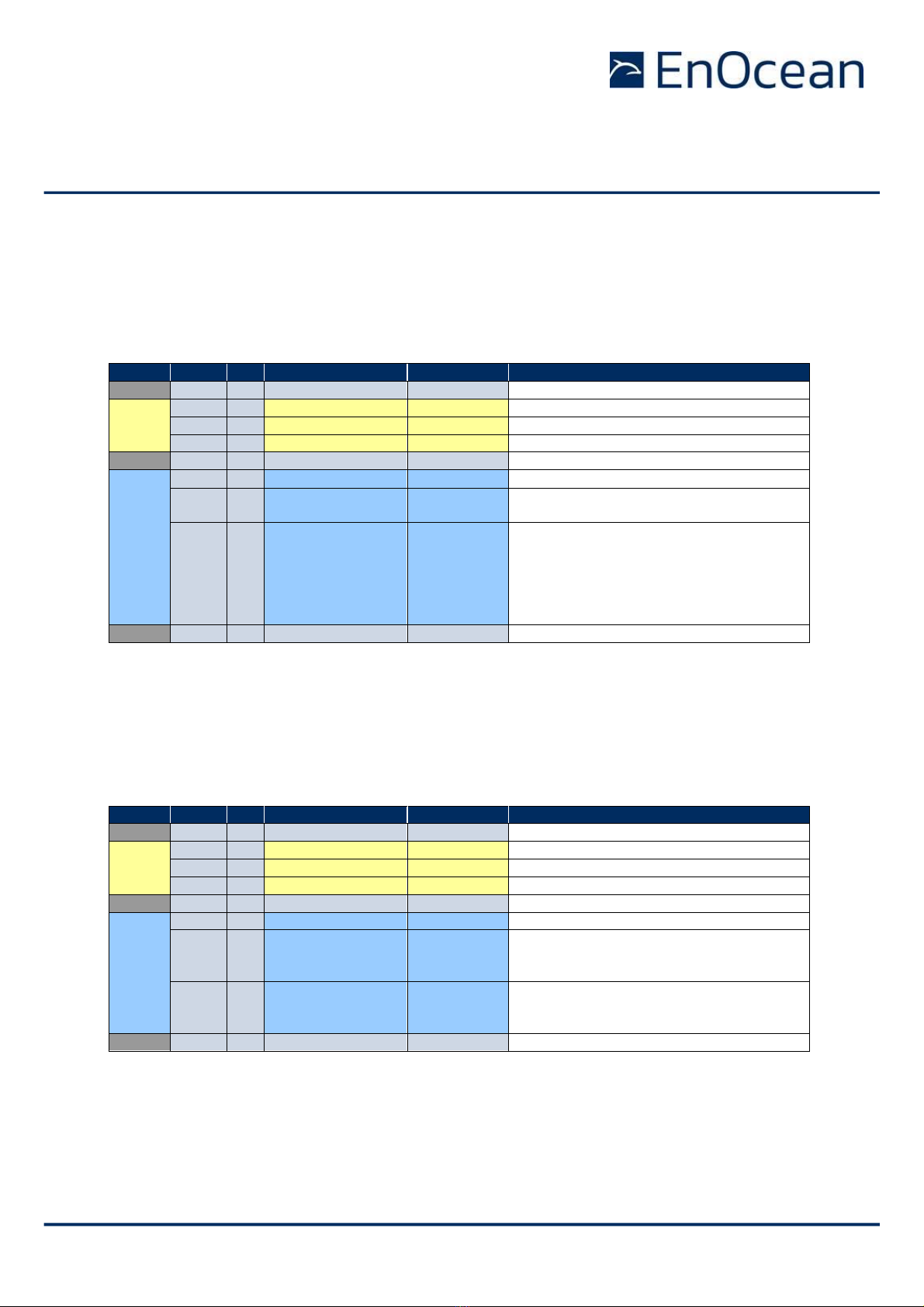
4.2.2 Filter definition
Telegram filters are defined using the CO_WR_FILTER_ADD command as shown in Table 3
below.
Group
Offset
Size
Field
Value hex
Description
-
0
1
Sync. Byte
0x55
Header
1
2
Data Length
0x0007
7 bytes
3
1
Optional Length
0x00
0 byte
4
1
Packet Type
0x05
COMMON_COMMAND = 5
-
5
1
CRC8H
0xnn
Data
6
1
COMMAND Code
0x0B
CO_WR_FILTER_ADD = 11
7
1
Filter criterium
0x00…0x03
Filter criterium to be used
0x00: Source address
0x01: Telegram type (R-ORG)
0x02: Minimum signal strength (dBm)
0x03: Destination address
8
4
Filter value
0xnnnnnnnn
Value to compare filter criterium against
- Source address
- R-ORG
- Signal strength (interpreted as negative
dBm, e.g. 85 -> -85 dBm)
- Destination address
12
1
Filter action
0x00
0x80
0x40
0xC0
0x00: Drop received telegram
0x80: Forward received telegram
0x40: Do not repeat received telegram
0xC0: Repeat received telegram
-
13
1
CRC8D
0xnn
Table 3 –CO_WR_FILTER_ADD
Each filter criterion can be defined as positive filter (message is forwarded / repeated if the
condition is true) or as negative filter (message is forwarded / repeated if the condition is
false). If for instance the filter condition is a certain source ID then it can be selected if only
telegrams originating from this source ID are repeated / forwarded (positive filter) or if all
messages except the one originating from this source ID are repeated / forwarded (negative
filter).
Moreover, for each filter criterion it can be defined if it shall apply for the forwarding func-
tionality or for the repeating functionality of TCM 515. The maximum number of filter criteria
is 30. Attempting to define more filter criteria will result in the response 01: RET_ERROR
(memory space full).
Note that more than one filter can be defined, e.g. it is possible to setup filter rules such that
telegrams originating from several source ID will be processed. If more than one filter con-
dition per functionality is defined then it can be defined if all conditions must be true (logical
AND) or one of the conditions must be true (logical OR).
USER MANUAL
TCM 515 –ENOCEAN TRANSCEIVER GATEWAY MODULE
© 2019 EnOcean | www.enocean.com F-710-017, V1.0 TCM 515 User Manual | v1.13 | August 2019 | Page 20/86
4.2.3 Filter enabling
Once all filters have been defined, the CO_WR_FILTER_ENABLE command shown in Table 4
below has to be used to select the logical relation between the defined filters (logical AND
versus logical OR) and to enable the filtering mechanism for telegram forwarding via ESP3.
Group
Offset
Size
Field
Value hex
Description
-
0
1
Sync. Byte
0x55
Header
1
2
Data Length
0x0003
3 bytes
3
1
Optional Length
0x00
0 byte
4
1
Packet Type
0x05
COMMON_COMMAND = 5
-
5
1
CRC8H
0xnn
Data
6
1
COMMAND Code
0x0E
CO_WR_FILTER_ENABLE = 14
7
1
Forward Filter
ON/OFF
0x00
0x01
0x00: Forwarding filter disabled
0x01: Forwarding filter enabled
8
1
Filter Operator
0x00
0x01
0x08
0x09
OR composition of all filters = 0
AND composition of all filters = 1
OR for radio interface filters; AND for fil-
tered repeating filters = 8
AND for radio interface filters; OR for fil-
tered repeating filters = 9
-
9
1
CRC8D
0xnn
Table 4 –Syntax for CO_WR_FILTER_ENABLE command
The use of filters for the repeater is enabled by means of the CO_WR_REPEATER command
shown in Table 5 below. There, REP_ENABLE has to be set to 0x02 to enable selective re-
peating based on the defined filters.
Group
Offset
Size
Field
Value hex
Description
-
0
1
Sync. Byte
0x55
Header
1
2
Data Length
0x0003
3 bytes
3
1
Optional Length
0x00
0 byte
4
1
Packet Type
0x05
COMMON_COMMAND = 5
-
5
1
CRC8H
0xnn
Data
6
1
COMMAND Code
0x09
CO_WR_REPEATER = 09
7
1
REP_ENABLE
0x00…0x02
0x00: No repeating
0x01: Repeating of all telegrams
0x02: Selective repeating
8
1
REP_LEVEL
0x00…0x02
0x00: No repeating
0x01: One level repeating
0x02: Two level repeating
-
9
1
CRC8D
0xnn
Table 5 –Syntax for CO_WR_REPEATER command
Other manuals for TCM 515
1
This manual suits for next models
1
Table of contents
Other EnOcean Transceiver manuals


