EnOcean TCM 310U User manual

USER MANUAL V1.2
EnOcean GmbH
Kolpingring 18a
82041 Oberhaching
Germany
Phone +49.89.67 34 689-0
Fax +49.89.67 34 689-50
info@enocean.com
www.enocean.com
Subject to modifications
TCM 310 / 310C / TCM 310U User Manual
July 28, 2014
Page 1/28
Patent protected:
WO98/36395, DE 100 25 561, DE 101 50 128,
WO 2004/051591, DE 103 01 678 A1, DE 10309334,
WO 04/109236, WO 05/096482, WO 02/095707,
US 6,747,573, US 7,019,241
Observe precautions! Electrostatic sensitive devices!
Transceiver Module
TCM 310 / TCM 310C / TCM 310U
July 22, 2014

USER MANUAL V1.2
© 2014 EnOcean | www.enocean.com TCM 310 / TCM 310C / TCM 310U User Manual | v1.2 | July 2014 | Page 2/28
TCM 310 / TCM 310C / TCM 310U
REVISION HISTORY
The following major modifications and improvements have been made to the first version of
this document:
No
Major Changes
1.00
Initial version
1.01
Modification for Step Code DB; increased number of filters and Smart Ack mail-
boxes
1.02
Supply voltage range extended
1.03
Start-up time and current consumption in deep sleep mode added in 2.2; im-
proved layout recommendations in 3.5
1.04
Antenna recommendations removed and referred to application note AN102 and
AN105; Maximum Rating for IOVDD modified (IOVDD may now exceed VDD); Ad-
ditional information in 3.6; Chapter “Related Documents” added; pin numbers
added in 3.2; update of FCC grant in 5.2; parameters for antenna requirements
relaxed in 4.2.1.;
1.05
Error in table in 3.2 corrected (pin 17 and 18 need to be connected to GND as
shown in figure above)
1.06
Supply voltage range extended; start-up time from sleep added
1.07
TCM 310U added
1.08
Mitsubishi Materials Chip Antenna added to limited modular approval
1.1
Updated power supply filter recommendation
1.15
Added Start-up Time Parameter, Changed Vmin
1.2
Duty cycle lock added in 3.6 and 5.1, and selective repeating added in 3.7
Published by EnOcean GmbH, Kolpingring 18a, 82041 Oberhaching, Germany
www.enocean.com, info@enocean.com, phone +49 (89) 6734 6890
© EnOcean GmbH
All Rights Reserved
Important!
This information describes the type of component and shall not be considered as assured characteris-
tics. No responsibility is assumed for possible omissions or inaccuracies. Circuitry and specifications
are subject to change without notice. For the latest product specifications, refer to the EnOcean web-
site: http://www.enocean.com.
As far as patents or other rights of third parties are concerned, liability is only assumed for modules,
not for the described applications, processes and circuits.
EnOcean does not assume responsibility for use of modules described and limits its liability to the
replacement of modules determined to be defective due to workmanship. Devices or systems contain-
ing RF components must meet the essential requirements of the local legal authorities.
The modules must not be used in any relation with equipment that supports, directly or indirectly,
human health or life or with applications that can result in danger for people, animals or real value.
Components of the modules are considered and should be disposed of as hazardous waste. Local
government regulations are to be observed.
Packing: Please use the recycling operators known to you.

USER MANUAL V1.2
© 2014 EnOcean | www.enocean.com TCM 310 / TCM 310C / TCM 310U User Manual | v1.2 | July 2014 | Page 3/28
TCM 310 / TCM 310C / TCM 310U
TABLE OF CONTENT
1MODULE VARIANTS AND RELATED DOCUMENTS ...............................................4
2GENERAL DESCRIPTION .................................................................................4
2.1 Basic functionality ......................................................................................... 4
2.2 Technical data...............................................................................................5
2.3 Physical dimensions.......................................................................................6
2.4 Environmental conditions ...............................................................................6
2.5 Ordering information...................................................................................... 6
3FUNCTIONAL DESCRIPTION............................................................................ 7
3.1 Pin out .........................................................................................................7
3.2 Pin description and operational characteristics...................................................7
3.2.1 GPIO supply voltage - IOVDD...................................................................... 8
3.3 Absolute maximum ratings (non operating) ......................................................8
3.4 Maximum ratings (operating)..........................................................................8
3.5 System environment...................................................................................... 8
3.6 Serial Interface .............................................................................................9
3.7 Built-in Repeater ......................................................................................... 10
3.8 Smart Acknowledge ..................................................................................... 11
3.9 Remote Management ................................................................................... 11
4APPLICATIONS INFORMATION....................................................................... 12
4.1 Transmission range ..................................................................................... 12
4.2 Antenna options .......................................................................................... 13
4.2.1 Overview................................................................................................ 13
4.2.2 Whip antenna ......................................................................................... 13
4.2.3 Helical antenna ....................................................................................... 14
4.2.4 Chip antenna (supplier: Mitsubishi Material, Type AM11DG-ST01) ................. 15
4.3 Recommendations for laying a whip antenna .................................................. 16
4.4 Power supply requirements........................................................................... 17
4.5 Layout recommendations ............................................................................. 17
4.5.1 Recommended foot pattern....................................................................... 18
4.6 Soldering information................................................................................... 21
4.7 Tape & Reel specification.............................................................................. 22
5AGENCY CERTIFICATIONS ............................................................................ 23
5.1 CE approval ................................................................................................ 23
5.2 FCC (United States) Certification ................................................................... 24
5.3 FCC Regulatory Statements ......................................................................... 26
5.4 IC (Industry Canada) Certification ................................................................. 27
5.5 Industry Canada Regulatory Statements ........................................................ 28

USER MANUAL V1.2
© 2014 EnOcean | www.enocean.com TCM 310 / TCM 310C / TCM 310U User Manual | v1.2 | July 2014 | Page 4/28
TCM 310 / TCM 310C / TCM 310U
1MODULE VARIANTS AND RELATED DOCUMENTS
This document describes operation of TCM 310 modules available in variations for following
frequencies:
TCM 310 : 868.300 MHz
TCM 310C: 315.000 MHz
TCM 310U: 902.875 MHz
In side this manual the following terms TCM 310x can be used interchangeably for any of
the above frequency.
This document describes operation of TCM 310x modules with their built-in firmware.
In addition we recommend following our application notes, in particular
AN101: Power Supply Layout –Layout considerations for Line-Power
AN102: Antenna Basics –Basic Antenna Design Considerations for EnOcean based
Products
AN105: 315 MHZ Internal Antenna Design –Considerations for EnOcean based Products
The specification of the serial protocol ESP3 can be found here:
http://www.enocean.com/en/enocean_modules/tcm-310/
2GENERAL DESCRIPTION
2.1 Basic functionality
TCM 310x is a SMD mountable radio transmitter mod-
ule enabling the realization of gateways for EnOcean
868 MHz, 315 MHz and 902 MHz radio systems. It pro-
vides a bi-directional radio interface and a bi-
directional serial interface. Radio messages are sent
transparently through the serial interface in both direc-
tions from and to an externally connected host proces-
sor or host PC. In addition control commands can be
sent from the host, e.g. to configure the repeater func-
tionality or to manage Smart Ack functions. TCM 310x
can act as postmaster for up to 20 bi-directional sen-
sors using Smart Ack technology.
Features
Smart Ack controller functionality
Transparent radio channel
Programmable repeater functionality (1 / 2 Level)
ESP3 support (EnOcean Serial Protocol V3)
Not API programmable!

USER MANUAL V1.2
© 2014 EnOcean | www.enocean.com TCM 310 / TCM 310C / TCM 310U User Manual | v1.2 | July 2014 | Page 5/28
TCM 310 / TCM 310C / TCM 310U
1) According to ISO/IEC 14543-3-10 2) @ 0.1% telegram error rate based on transmitted sub-telegrams
2.2 Technical data
Antenna
TCM 310 : external whip or 50 Ω antenna mountable
TCM 310C: external whip
TCM 310U: external whip or Helical antenna
Frequency
TCM 310 : 868.300 MHz (ASK)1)
TCM 310C: 315.000 MHz (ASK)1)
TCM 310U: 902.875 MHz (FSK)
Radio Standard
Enocean 868 MHz/315 MHz: ISO/IEC 14543-3-10
Data rate/Modulation type
125 kbps
Receiver Sensitivity (at 25 °C)
typ. –96 dBm (868.300 MHz) 2)
typ. -98 dBm (315.000 MHz) 2)
typ. -98 dBm (902.875 MHz) 2)
Conducted Output Power
typ. 3 dBm @ 315 and 868 MHz / 1 dBm @ 902.875 MHz
Power Supply
2.6V … 3.5 V
Start-up Time
<500ms
Serial Interface
UART
Current Consumption
Receive mode: 33 mA
Transmit mode: 24 mA
Dimensions of PCB
22x19x3 mm
Operating temperature
0 to +65 °C
Radio Regulations
R&TTE EN 300 220 (TCM 310) v.2.4.1
FCC CFR-47 Part 15 (TCM 310C / TCM 310U)

USER MANUAL V1.2
© 2014 EnOcean | www.enocean.com TCM 310 / TCM 310C / TCM 310U User Manual | v1.2 | July 2014 | Page 6/28
TCM 310 / TCM 310C / TCM 310U
2.3 Physical dimensions
TCM 310 (pads on bottom side of PCB!)
2.4 Environmental conditions
Operating temperature -0 °C … +65 °C
Storage temperature -40 °C … +85 °C
Storage temperature in tape & reel package -20 °C … +50 °C
Humidity 0% … 93% r.H., non-condensing
2.5 Ordering information
Type
Ordering Code
Frequency
TCM 310
S3003-K310
868.300 MHz
TCM 310C
S3033-K310
315.000 MHz
TCM 310U
S3053-K310
902.875 MHz
PCB Dimension 22 x 19 x 3.1 mm
Weight 1.9 g
Unless otherwise specified dimensions are in mm.
Tolerances:
PCB outline dimensions 0.2 mm
All other tolerances 0.1 mm

USER MANUAL V1.2
© 2014 EnOcean | www.enocean.com TCM 310 / TCM 310C / TCM 310U User Manual | v1.2 | July 2014 | Page 7/28
TCM 310 / TCM 310C / TCM 310U
3FUNCTIONAL DESCRIPTION
3.1 Pin out
The figure above shows the pin out of the TCM 310x hardware.
3.2 Pin description and operational characteristics
HW Symbol
Pin #
Function
Characteristics
GND
1, 5, 7, 17, 18,
24, 26, 28, 31
Ground connection
Must be connected to GND; see 4.4
VDD
2
Supply voltage
2.6 V … 3.5 V
RVDD
8
RF supply voltage
regulator output
Leave open
DVDD
25
Digital supply volt-
age
regulator output
1.8 V
Output current: max. 5 mA
IOVDD
23
GPIO supply volt-
age
Must be connected to desired inter-
face supply voltage (see 3.4) See
also 3.2.1.
RESET
27
Reset input
External 10 kΩ pull-down required.
SER_RX
15
UART input
See 3.6
SER_TX
16
UART output
See 3.6
RF_WHIP
4
RF output
Output for whip antenna
RF_50
6
RF output
50 Ohm output for external antenna
n.c.
3, 9-14, 19-22,
29,30, 32-34
Not connected
Do not connect!
EO3000I
Antenna
balun
XTAL
16MHz
TCM310/310C
TOP VIEW
DVDD
RVDD
n.c.
IOVDD
n.c.
n.c.
n.c.
n.c.
RESET
n.c.
n.c.
n.c.
n.c.
n.c.
n.c.
n.c.
SER_RX
SER_TX
GND
n.c.
n.c.
n.c.
GND
GND
GND
RF_50
RF_WHIP
n.c.
VDD
GND
GND
GND
GND
GND
1
918
26
USER MANUAL V1.2
© 2014 EnOcean | www.enocean.com TCM 310 / TCM 310C / TCM 310U User Manual | v1.2 | July 2014 | Page 8/28
TCM 310 / TCM 310C / TCM 310U
3.2.1 GPIO supply voltage - IOVDD
For digital communication with other circuitry the pins of the serial interface UART may be
operated from supply voltages different from DVDD. Therefore an interface voltage supply
pin IOVDD is available which must be connected either to DVDD or to an external supply
within the tolerated voltage range of IOVDD.
If DVDD=0 V (e.g. in any sleep mode or if VDD<VOFF) and IOVDD is supplied,
there may be unpredictable and varying current from IOVDD caused by internal
floating nodes. It must be taken care that the current into IOVDD does not exceed
10 mA while DVDD=0 V. If DVDD=0 V and IOVDD is not supplied, do not apply
voltage to any above mentioned pin. This may lead to unpredictable malfunction
of the device.
IOVDD voltage must not exceed VDD voltage! A malfunction of the module may be
caused by such inverse supply!
3.3 Absolute maximum ratings (non operating)
Symbol
Parameter
Min
Max
Units
VDD
Supply voltage at VDD
-0.5
5.5
V
IOVDD
GPIO supply voltage
-0.5
3.6
V
GND
Ground connection
0
0
V
VIND1
Voltage at RESET, and UART
-0.5
3.6
V
3.4 Maximum ratings (operating)
Symbol
Parameter
Min
Max
Units
VDD
Supply voltage at VDD
TCM 310
2.6
3.5
V
IOVDD
GPIO supply voltage (see also 3.2.1)
1.7
3.6
V
GND
Ground connection
0
0
V
VIND1
Voltage at RESET, and UART
0
3.6
V
VDDR
Max. ripple at VDD
50
mVpp
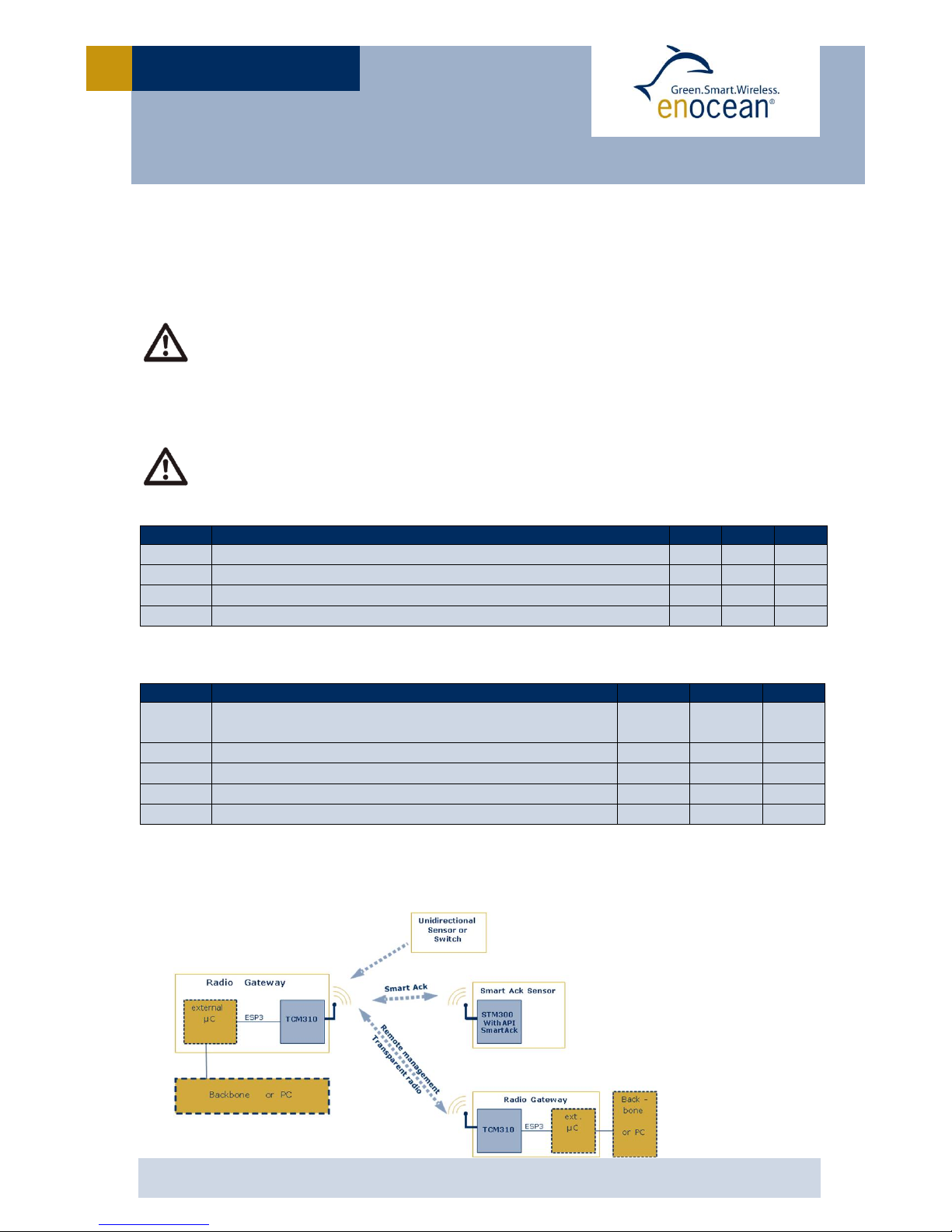
3.5 System environment
In the figure below, TCM 310x is shown in a typical system environment.

USER MANUAL V1.2
© 2014 EnOcean | www.enocean.com TCM 310 / TCM 310C / TCM 310U User Manual | v1.2 | July 2014 | Page 9/28
TCM 310 / TCM 310C / TCM 310U
3.6 Serial Interface
TCM 310x provides a bi-directional serial interface which conforms to the EnOcean ESP3
specification. For details regarding ESP3 please refer to the ESP3 specification1. The data
rate on the serial interface is 58.8 kbit/s which is usually interoperable with systems run-
ning at 57.6 kbit/s.
Direction
Nominal serial data rate
Tolerance
TX (sent by module)
58823 bit/s (=57600 bit/s + 2.1%)
< 50 ppm
RX (received by module)
58823 bit/s
< 5%
The following ESP3 commands are supported:
Type 1 Radio command for transparent mode
Type 2 Responses
Type 4 Event
oSA_CONFIRM_LEARN to confirm/discard learn in/out
oCO_READY to indicate wake up from deep sleep initiated by CO_WR_SLEEP
oCO_DUTYCYCLE_LIMIT to inform about a current limitation due to duty cycle
Type 5 Common commands
oCO_WR_SLEEP to enter energy saving mode (deep sleep mode)
oCO_WR_RESET to reset the device
oCO_RD_VERSION to read SW/HW versions, chip ID etc.
oCO_RD_SYS_LOG to read system log from device data base
oCO_WR_SYS_LOG to reset system log from device data base
oCO_WR_BIST to perform flash BIST operation
oCO_WR_IDBASE to write ID range base number
oCO_RD_IDBASE to read ID range base number
oCO_WR_REPEATER to configure repeater functionality
oCO_RD_REPEATER to read repeater state
oCO_WR_FILTER_ADD to add filter to filter list or to selective repeating
(up to 30 filters are supported)
oCO_WR_FILTER_DEL to delete filter from filter list or from selective repeating
oCO_WR_FILTER_DEL_ALL to delete all filter
oCO_WR_FILTER_ENABLE to enable/disable supplied filters
oCO_RD_FILTER to read supplied filters
oCO_WR_WAIT_MATURITY to wait maturity time before returning radio telegrams
oCO_WR_MEM for writing into memory
oCO_RD_MEM for reading memory
oCO_RD_MEM_ADDRESS to get addresses of special areas
oCO_RD_DUTYCYCLE_LIMIT to read information about current duty cycle limitations
Type 6 Smart Acknowledge commands
oSA_WR_LEARNMODE to set/reset Smart Acknowledge learn mode
oSA_RD_LEARNMODE to get learn mode
oSA_WR_LEARNCONFIRM to add or delete a mailbox of a client
oSA_WR_RESET to send a reset command to a client
oSA_RD_LEARNEDCLIENTS to get learned mailboxes/clients
oSA_WR_POSTMASTER to activate/deactivate post master functionality
Type 7 Remote Management messages up to 256 Bytes
1http://www.enocean.com/en/enocean_modules/tcm-310/

USER MANUAL V1.2
© 2014 EnOcean | www.enocean.com TCM 310 / TCM 310C / TCM 310U User Manual | v1.2 | July 2014 | Page 10/28
TCM 310 / TCM 310C / TCM 310U
3.7 Built-in Repeater
TCM 310x provides the option to activate a one or two-level repeater for EnOcean radio
telegrams.
1-level repeater: If a received telegram is a valid and original (not yet repeated), the tele-
gram is repeated after a random delay. This delay will be chosen such that the maximum
TX maturity time (as standardized in ISO 14543-3-10) of 40ms will not be exceeded.
2-level repeater: If a received telegram is valid and original or repeated once, the telegram
is repeated after a random delay. This delay will be chosen such that the maximum TX ma-
turity time (as standardized in ISO 14543-3-10) of 40ms will not be exceeded.
Repeated telegrams are marked as “repeated” by an increased repeater counter. Configura-
tion of the repeater functionality is done via serial interface commands.
For detailed recommendations regarding the usage of repeaters please refer to our applica-
tion note EnOcean Wireless Systems - Installation Notes (PDF), 09/2010.
TCM310x also provides selective repeating. It is possible to add filters and these will be
applied during repeating. Selective repeating can be done based on:
Sender ID
Destination ID
RORG
dBm value
It is possible to define white lists or black lists for selective repeating and for filtering of
received radio telegrams passed via ESP3 independently.
All configuration values set via ESP3 commands are held in RAM and will therefore
be lost after RESET or after a deep sleep phase. Only Smart Ack mailboxes are
stored in FLASH and are available also after RESET or a deep sleep phase.
After sending a CO_WR_RESET command, the following CO_READY event indi-
cates wake up reason 06 meaning ”A memory request from the CPU core does not
correspond to any valid memory location.” This is caused by the real reset cause
used when CO_WR_RESET will be performed. It is not a SW/HW malfunction.
When using repeaters, care must be taken to ensure that regulatory transmitter
duty cycle limits (if applicable) are not exceeded.
2-level repeating function should only be activated after careful study of the radio
conditions! Otherwise the system function can be compromised by collisions of
telegrams.
USER MANUAL V1.2
© 2014 EnOcean | www.enocean.com TCM 310 / TCM 310C / TCM 310U User Manual | v1.2 | July 2014 | Page 11/28
TCM 310 / TCM 310C / TCM 310U
3.8 Smart Acknowledge
TCM 310x provides a post master function with 20 mailboxes for sensors using Smart Ac-
knowledge technology. For more information on smart acknowledge please refer to the
EnOcean End Equipment Profiles (EEP) 2.6 specification.
When teaching-in a device using Smart Acknowledge please take care to switch off
all TCM 3xy devices which are not continuously powered. Otherwise these TCM
3xy modules could be declared postmaster.
If power supply to such postmaster will be switched off then Smart Acknowledge
would not work due to the absence of the postmaster.
Smart Ack radio telegrams will be received and internally processed (post master,
mailbox, etc.). There is no forwarding of such telegrams to the serial ESP3 inter-
face.
3.9 Remote Management
TCM 310x provides a transparent radio channel also for remote management messages
with a message length of up to 256 bytes. This enables an external micro controller con-
nected to TCM 310 to handle remote management request from external devices or to con-
trol other devices via remote management.
For more information on remote management please refer to the EnOcean End Equipment
Profiles (EEP) 2.5 specification.

USER MANUAL V1.2
© 2014 EnOcean | www.enocean.com TCM 310 / TCM 310C / TCM 310U User Manual | v1.2 | July 2014 | Page 12/28
TCM 310 / TCM 310C / TCM 310U
4APPLICATIONS INFORMATION
4.1 Transmission range
The main factors that influence the system transmission range are type and location of the
antennas of the receiver and the transmitter, type of terrain and degree of obstruction of
the link path, sources of interference affecting the receiver, and “dead” spots caused by
signal reflections from nearby conductive objects. Since the expected transmission range
strongly depends on this system conditions, range tests should categorically be performed
before notification of a particular range that will be attainable by a certain application.
The following figures for expected transmission range are considered by using a PTM, a
STM or a TCM radio transmitter device and the TCM radio receiver device with preinstalled
whip antenna and may be used as a rough guide only:
Line-of-sight connections: Typically 30 m range in corridors, up to 100 m in halls
Plasterboard walls / dry wood: Typically 30 m range, through max. 5 walls
Line-of-sight connections: Typically 30 m range in corridors, up to 100 m in halls
Ferro concrete walls / ceilings: Typically 10 m range, through max. 1 ceiling
Fire-safety walls, elevator shafts, staircases and supply areas should be considered as
screening.
The angle at which the transmitted signal hits the wall is very important. The effective wall
thickness –and with it the signal attenuation –varies according to this angle. Signals
should be transmitted as directly as possible through the wall. Wall niches should be
avoided. Other factors restricting transmission range:
Devices mounted on metal surfaces (shielding and detuning of antenna may cause heavy
loss of transmission range)
Hollow lightweight walls filled with insulating wool on metal foil
Suspended ceilings with panels of metal or carbon fibre
Lead glass or glass with metal coating, steel furniture
The distance between EnOcean receivers and other transmitting devices such as com-
puters, audio and video equipment that also emit high-frequency signals should be at least
0.5 m
A summarized application note to determine the transmission range within buildings is
available as download from www.enocean.com.
USER MANUAL V1.2
© 2014 EnOcean | www.enocean.com TCM 310 / TCM 310C / TCM 310U User Manual | v1.2 | July 2014 | Page 13/28
TCM 310 / TCM 310C / TCM 310U
4.2 Antenna options
4.2.1 Overview
Several antenna types have been investigated by EnOcean. Please refer to our application
notes AN102, and AN105 which give an overview on our recommendations.
All TCM 310x modules have been approved with whip antenna, and TCM 310U with helical
antenna in addition.
868.300 MHz modules used in Europe do not need additional approval if alternative used
external antenna fulfils the following requirements:
Frequency
band
868.300 MHz
ISM
Antenna must be suited for this band
Antenna type
Passive
Mandatory for radio approval
Impedance
~50 Ohm
Mandatory for radio approval
Maximum gain
≤ 0 dBd
Mandatory for radio approval
In addition it is important to fulfill the following requirements in order to achieve compati-
bility with other EnOcean products and to ensure excellent EMI robustness:
VSWR
≤ 3:1
Important for compatibility with EnOcean protocol
Return Loss
> 6 dB
Important for compatibility with EnOcean protocol
Bandwidth
≤ 20 MHz
Important if 10 V/m EMI robustness required for device
For 315 MHz / 902.875 MHz modules (TCM 310C / TCM 310U) please note
that a full approval is needed if modules are used with antennas other than
the specified antennas.
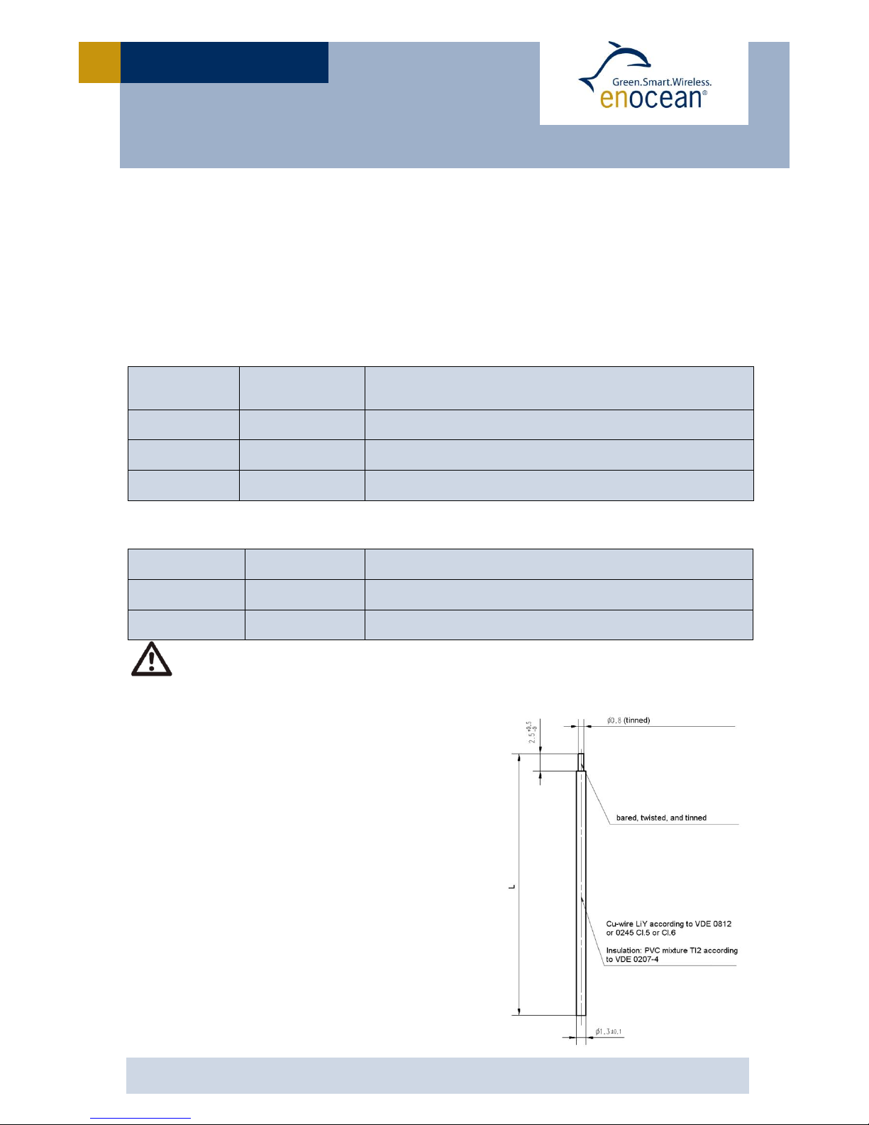
4.2.2 Whip antenna
315 MHz
Antenna: 150 mm wire, connect to RF_WHIP
Minimum GND plane: 50 mm x 50 mm
Minimum distance space: 10 mm
868.3 MHz
Antenna: 86 mm wire, connect to RF_WHIP
Minimum GND plane: 38 mm x 18 mm
Minimum distance space: 10 mm
902.875 MHz
Antenna: 64 mm wire, connect to RF_WHIP
Minimum GND plane: 50 mm x 50 mm
Minimum distance space: 10 mm

USER MANUAL V1.2
© 2014 EnOcean | www.enocean.com TCM 310 / TCM 310C / TCM 310U User Manual | v1.2 | July 2014 | Page 14/28
TCM 310 / TCM 310C / TCM 310U
4.2.3 Helical antenna
315 MHz
please contact EnOcean for availability
868.3 MHz
according to drawing below, connect to RF_WHIP
please contact EnOcean for MOQ
Minimum GND plane: 35 mm x 30 mm
Minimum distance space: 10 mm
902.875 MHz
limited modular approval available
please contact EnOcean for MOQ and mandatory limited modular approval user agreement
according to drawing below, connect to RF_WHIP
Minimum GND plane: 35 mm x 30 mm
Minimum distance space: 10 mm
USER MANUAL V1.2
© 2014 EnOcean | www.enocean.com TCM 310 / TCM 310C / TCM 310U User Manual | v1.2 | July 2014 | Page 15/28
TCM 310 / TCM 310C / TCM 310U
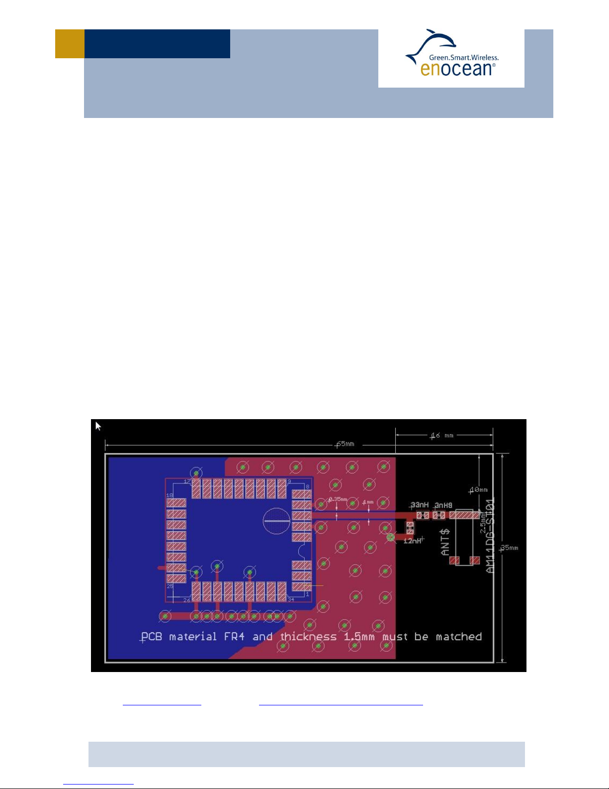
4.2.4 Chip antenna (supplier: Mitsubishi Material, Type AM11DG-ST01)
315 MHz
Modular approval not available. Range and gain significantly reduced because of antenna
size vs. the wavelength. Small chip antennas at this frequency may be suited for space-
constrained applications. Check with supplier for matching circuit and board design guide-
lines. Supplier can make recommendations or do testing to optimize individual PCB design.
868.3 MHz
Additional matching circuit and proper board design is required.
Check with supplier for matching circuit and board design guidelines.
Connect matching circuit to RF_50 using 50 Ohm strip lines. Please follow 902 MHz board
design recommendations and dimensions. Be aware that matching values differ!
902.875 MHz
Limited modular approval is available. Please contact EnOcean to sign the mandatory lim-
ited modular approval user agreement. Dimensions may not be shortened. Matching circuit
is part of the limited modular approval and may not be changed. Minimum top and bottom
side ground plane required as shown below. Connect ground planes using multiple via as
shown. Connect matching circuit to RF_50. Use High Q wire wound inductors, e.g. 0603
Murata LQW18A series. Matching circuits values: L1 = 3.9 nH; L2 = 33 nH, L3 = 12 nH.
This antenna evaluation board is available upon request for use with EnOcean EDK 350 de-
veloper kit.
For any further questions or chip antenna quotes, please refer to Mitsubishi Materials web-
site at www.mmea.com or email to electroniccomponents@mmus.com.
USER MANUAL V1.2
© 2014 EnOcean | www.enocean.com TCM 310 / TCM 310C / TCM 310U User Manual | v1.2 | July 2014 | Page 16/28
TCM 310 / TCM 310C / TCM 310U
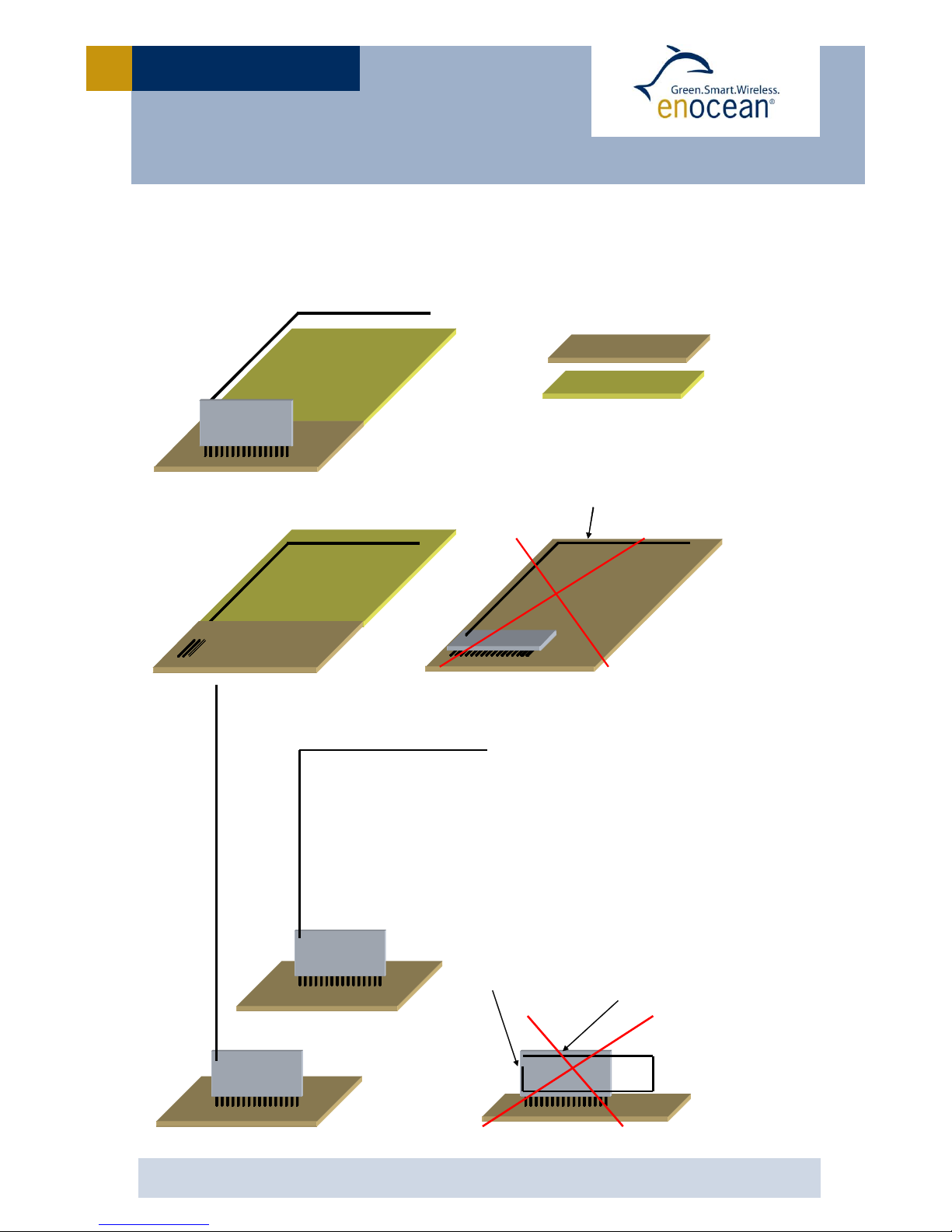
4.3 Recommendations for laying a whip antenna
Antenna too close
to GND area
Antenna end led
back to foot point
PCB
with
GND
PCB
without
GND
Antenna
too
close
to GND
area

USER MANUAL V1.2
© 2014 EnOcean | www.enocean.com TCM 310 / TCM 310C / TCM 310U User Manual | v1.2 | July 2014 | Page 17/28
TCM 310 / TCM 310C / TCM 310U
4.4 Power supply requirements
In order to provide a good radio performance, great attention must be paid to the power
supply and a correct layout and shielding. It is recommended to place a 22 µF ceramic ca-
pacitor between VDD and GND close to the module (material: X5R, X7R, min 6.3 V to avoid
derating effects).
In addition, an HF SMD EMI Suppression Ferrite Bead such as the Würth WE-CBF HF SMD
EMI Suppression Ferrite Bead (Würth order number 742863160) shall be inserted in the
power supply line.
For best performance it is recommended to keep the ripple on the power supply rail below
10 mVpp (see 3.4).
All GND pins must be connected to GND. Be careful not to create loops! The
ground must be realized ideally on both sides of the PCB board with many vias. At
least there must be a short star connection. Otherwise RF performance can be
reduced!
4.5 Layout recommendations
The length of lines connected to I/Os should not exceed 5 cm.
It is recommended to have a complete GND layer in the application PCB, at least
in the area below the module and directly connected components (e.g. mid-layer
of your application PCB).
Due to unisolated test points there are live signals accessible on the bottom side
of the module.
Please follow the following advices to prevent interference with your application
circuit:
We suggest avoiding any copper structure in the area directly underneath
the module (top-layer layout of your application PCB). If this is not possible
in your design, please provide coating on top of your PCB to prevent short
circuits to the module. All bare metal surfaces including vias have to be
covered (e.g. adequate layout of solder resist).
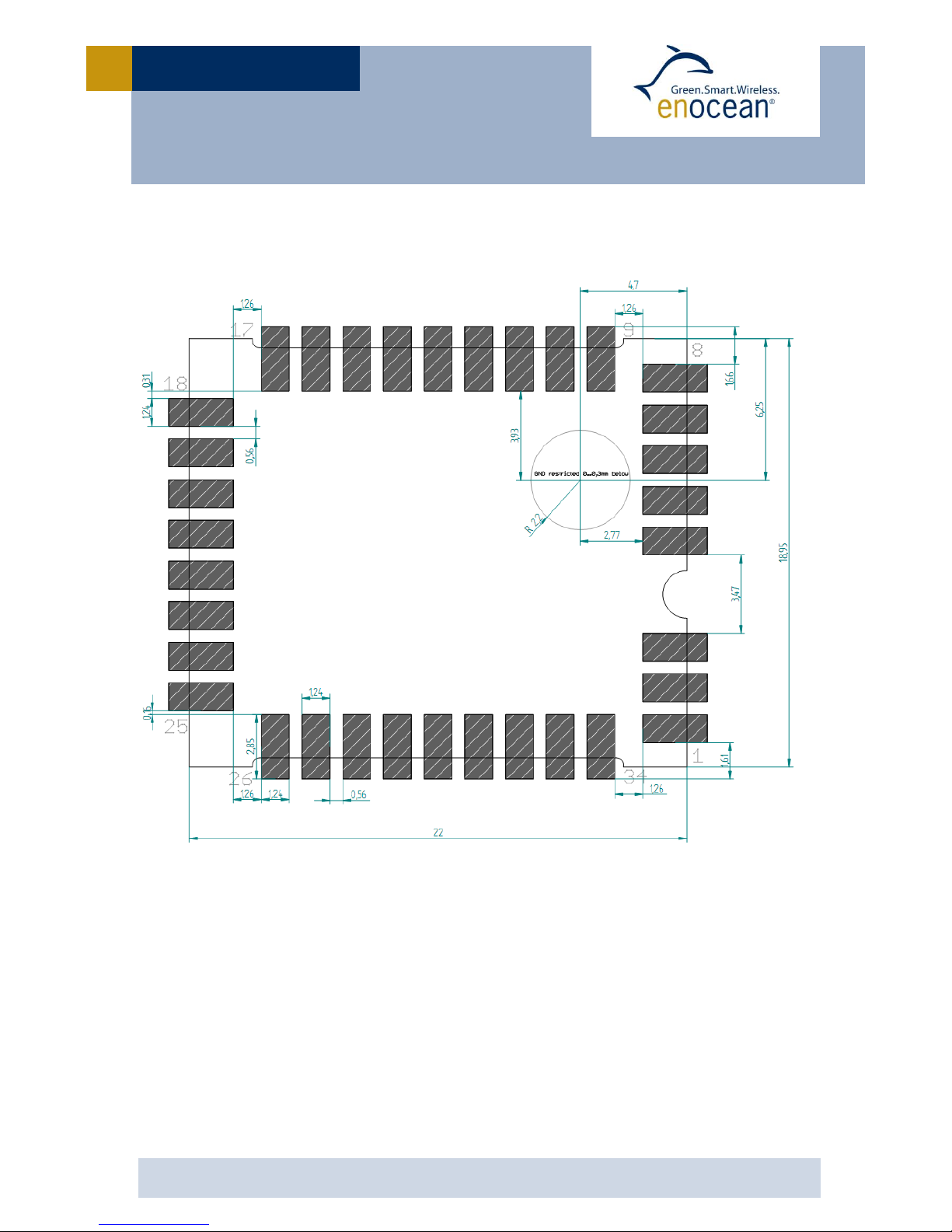
It is mandatory that the area marked by the circle in the figure below is
kept clear of any conductive structures in the top layer and 0.3 mm below.
Otherwise RF performance will be degraded!
Furthermore, any distortive signals (e.g. bus signals or power lines) should not be
routed underneath the module. If such signals are present in your design, we sug-
gest separating them by using a ground plane between module and these signal
lines.

USER MANUAL V1.2
© 2014 EnOcean | www.enocean.com TCM 310 / TCM 310C / TCM 310U User Manual | v1.2 | July 2014 | Page 18/28
TCM 310 / TCM 310C / TCM 310U
4.5.1 Recommended foot pattern
Top layer

USER MANUAL V1.2
© 2014 EnOcean | www.enocean.com TCM 310 / TCM 310C / TCM 310U User Manual | v1.2 | July 2014 | Page 19/28
TCM 310 / TCM 310C / TCM 310U
Solder resist top layer
USER MANUAL V1.2
© 2014 EnOcean | www.enocean.com TCM 310 / TCM 310C / TCM 310U User Manual | v1.2 | July 2014 | Page 20/28
TCM 310 / TCM 310C / TCM 310U
Solder paste top layer
The data above are also available as EAGLE library.
In order to ensure good solder quality a solder mask thickness of 150 µm is recommended.
In case a 120 µm solder mask is used, it is recommended to enlarge the solder print. The
pads on the solder print should then be 0.1 mm larger than the pad dimensions of the
module as specified in chapter 2.3. (not relative to the above drawing).
Nevertheless an application and production specific test regarding the amount of soldering
paste should be performed to find optimum parameters.
Table of contents
Other EnOcean Transceiver manuals


