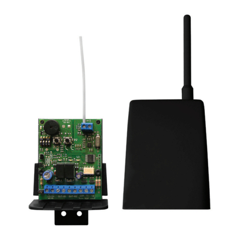
EB TECHNOLOGY TX-MINI User manual

TRASNCEIVER-RX-TXMINI_130515_VXX15_IT-GB-FR-DE-ES www.ebtechnology.it www.nolgo.info
TRANSCEIVER
RX
TX
V2
100%
ITALY
• Sistema via radio 868Mhz FM bidirezionale
senza fi li che trasmette il segnale di una si-
curezza al quadro di controllo.
• Il ricevitore verifi ca costantemente lo stato dei
trasmettitori connessi.
• Gestione fi no a n° 16 trasmettitori TRANS-
CEIVER-TX
• 868 Mhz bidirektionale drahtlose Funkeinheit,
zur Signalübertragung.
• Der Empfänger (RX) kontrolliert ständig den
Status des verbundenen Funksenders (TX).
• Er kann bis zu 16 Funksender TRANCEIVER-
TX regeln.
• 868 Mhz radio bidirectional device, wireless
which transmits a signal to a control device.
• The receiver constantly checks the status of
the transmitters connected to it.
• It can manages up to 16 transmitters TRAN-
CEIVER-TX.
• Système radio 868Mhz FM bidirectionnel sans
fil qui transmet le signal à partir d’un dispositif
de sécurité pour le dispositif de contrôle.
• Le récepteur surveille l’état d’émetteurs con-
nectés.
• Gère jusqu’à 16 émetteurs TRANSCEIVER-TX
IT GB
FR DE
• Sistema vía radio 868Mhz bidireccional ina-
lámbrico que transmite la señal de seguridad
al Tablero de control.
• El receptor comprueba costantemente el es-
tado de los transmisores conectados.
• Gestión hasta 16 transmisores TRANSCEIV-
ER-TX.
ES
868 Mhz radio bidirectional device, wireless

Prescrizioni Generali
eb technology srl si riserva il diritto di apportare eventuali modifi che al prodotto senza preavviso; inoltre declina
ogni responsabilità per danni a persone o cose dovuti ad un uso improprio del prodotto diverso da quanto
previsto nel presente manuale. Leggere attentamente il seguente manuale di istruzioni prima di procedere con
l’installazione e la programmazione del sistema.
• Il presente manuale di istruzioni è destinato solamente a personale tecnico qualifi cato nel campo delle in-
stallazioni di automazioni.
• Qualsiasi operazione di manutenzione o di programmazione deve essere eseguita esclusivamente da perso-
nale qualifi cato in quanto la modifi ca del progetto o della confi gurazione dell’apparato senza la consultazione
del fabbricante o del suo rappresentante autorizzato può creare situazioni pericolose.
Questo dispositivo soddisfa i requisiti della categoria 2 della EN 954-1 solo se usato in confi gurazione TEST a
controllo attivo DIP-1 TX & RX OFF.
Verifi care sul prodotto la presenza e la leggibilità della marcatura CE, in essa sono indicati: lotto di produzione.
eensione nominale, corrente nominale e grado di protezione IP.
E’ importante informare l’utilizzatore fi nale dei seguenti punti:
• Sostituire le batteria del modulo TX almeno ogni 12 mesi per garantire sempre il corretto funzionamento,
verifi care dopo la sostituzione le funzionalità del sistema.
• Prima della chiusura del contenitore del modulo TX, accertarsi che guarnizione e sede relativa siano intere e
pulite. Se neccessario, rimuovere con un panno residui di spocizia. Contattare eB technology per eventuali
ricambi.
• Le aree che danno accesso ai dispositivi devono essere tenute libere da ostacoli.
E’ necessario installare un fusibile sui contatti relè di uscita, con valore ≤ 100 mA e tensione ≥ 60 V
I dispositivi di sicurezza devono essere fatti conoscere a tutte le persone appropriate.
Installazione e Manutenzione
Impiego
TX
N.C. / 8,2k
TX TX
RX
Applicazione su automazione scorrevole
TX
RX
Applicazione su porta
ad impacchettamento rapido
Le restrizioni d’uso sono le seguenti:
• Chiuse e paratie
• Porte di ascensori
• Porte di veicoli
• Porte principalmente usate per la custodia di animali
• Tende in tessuto per teatro, Barriere ferroviarie
• Barriere utilizzate solo per veicoli, Dispositivi e apparati di sicurezza per macchine diverse dalle porte.
Il dispositivo inoltre non può essere utilizzato solamente per il controllo manuale e per l’arresto, anche d’emer-
genza, delle porte motorizzate.
Il prodotto può essere utilizzato su impianti di automazione di cancelli scorrevoli e portoni sezionali industriali.
La velocità massima dell’automazione dovrà essere di 60 m/min, in quanto il tempo di risposta del sistema è
pari a 100 ms.
Prescrizioni Generali

2002/95/EC
Ernestino Bandera
Busto Arsizio, 27/11/2014
Dimensioni b50 x h160 x d25 mm
Alimentazione 2 batterie LR06/AA
(1,5V-2600mAh)
Temperatura di esercizio -15 ÷ +50 °C
Autonomia in stand-by TX - DIP1 OFF 1 anno
TX - DIP1 ON 2 anni
Portata massima 20 m
Ingressi 2
Grado di protezione IP54 Test a pressione ambiente
Plastiche POLICARBONATO PC spessore: > 3 mm
TRANSCEIVER-TXMINI TRANSCEIVER-RX
è conforme alle seguenti disposizioni pertinenti:
ETSI EN 301 489-3 EN 300 220-1 EN 300 220-3 EN 60950: 1997 1999/5/CEE
2004/108/CE 2006/95/CE EN 954-1 (categoria 2)
Questo dispositivo è considerato come un componente operante in combinazione con altri sistemi. Le caratteristiche EMC possono subire delle
variazioni in funzione del tipo d’installazione quindi una verifi ca delle caratteristiche EMC dell’intero impianto è necessaria.
Il seguente prodotto risponde alle normative vigenti solo se collegato con TEST
Dichiarazione CE conformità
Caratteristiche tecniche
Dimensioni b65 x h81 x d30 mm
Alimentazione
12/24 Vac/dc
Con isolamento dalla rete
elettrica non inferiore a quello
tra circuito primario e secon-
dario di un trasformatore di
sicurezza conforme alla IEC
61558-2-6 o equivalente. Nel
caso la fonte d’alimentazione
sia in corrente continua con
potenza superiore a 100VA
(>8A), è necessario interporre
un sezionatore adeguato tra
questa ed il modulo RX.
Corrente assorbita 70 mA
Temperatura di esercizio -20 ÷ +60 °C
Numero TX memoralizzabili max 16 TX
Grado di protezione IP44
Plastiche ABS
spessore: > 2 mm
Contatti relè 1 e 2 di uscita
Carico di tipo resistivo, ten-
sione massima sul contatto
Na/Nc <= 30 Vac oppure <=
60 Vdc, corrente 1…100mA.
Adatto per circuiti di tipo
SELV.
RX
5mm 25mm
160mm 140mm
TX
75 mm
95 mm
195 mm
40 mm
25 mm

TX-MINI
COM. COSTE
ING. 1 COSTA
- BATTERIA
+ BATTERIA
- ANTENNA
+ ANTENNA
DIP 2 - Ingresso 1
OFF - contatto NC
ON - contatto 8,2K
DIP 3 - Ingresso 2
OFF - contatto NC
ON - contatto 8,2K
12 Vac/dc 24 Vac/dc
RX
+ ANTENNA
- ANTENNA
JUMPER J12
87
1234
JUMPER N/R
N A
NC
12 3 4 5 6 7 8 9
+ 12/24 Vac/dc
- 12/24 Vac/dc
OUT N/R 1
OUT N/R 2
COM TEST
TEST T1
TEST T2
9
ING. 2 COSTA
ON
P1
LED
TX1
P2
P1
PROG
P2
CHECK
BUZZER
LED
OUT1
N/R1 N/R2
ON
LED
OUT2
LED
RX1
-4-
TRANSCEIVER v2 Manuale tecnico
Schema e collegamenti elettrici
Leggere attentamente il manuale
Leggere attentamente questo manuale pri-
ma di utilizzare il prodotto e conservare il
manuale per futuro riferimento.

3Tenere premuto il pulsante P1 PROG del ricevitore per 12 secondi.
Al suono del Buzzer rilasciare
TRANSCEIVER v2 Manuale tecnico
-5-
1Posizionare tutti i DIP in OFF sia del TX che del RX
2
Alimentare RX 12/24 ac/dc se 12V ponticellare Jumper12V
Il LED-RX1 emette un lampeggio veloce
contemporaneamente ad un beep del buzzer.
7Premere e tenere premuti contemporaneamente i pulsanti P1 e P2
del trasmettitore
8Dopo 5 secondi il led si accende indicando l‘avvenuta cancellazione.
Rilasciare quindi pulsanti. Viene cosi cancellata la memoria del trasmettitore.
Prima installazione
Ricevitore
Reset della memoria del ricevitore
Questa operazione deve essere effettuata sempre al primo utilizzo.
Trasmettitore
4Collegare nei morsetti del TX il contatto di sicurezza NC
oppure il contatto sicurezza resistiva 8,2k
5
Selezionare con il DIP-2 per ING 1 e DIP-3 per ING 2, il tipo di ingresso:
OFF seleziona l’ingresso per un contatto NC
ON seleziona l’ingresso per un contatto resistivo a 8,2 K
6Alimentare TX con 2 Batterie da 1,5V tipo LR06 AA
Il LED-TX1 emette un lampeggio veloce e poi si spegne
Reset della memoria del trasmettitore
Questa operazione deve essere effettuata sempre al primo utilizzo.
P1 PROG
>
P1 PROG
>
BUZZER
Ing. COSTA 1
COM coste
Ing. COSTA 2
7
8
9
led
TX1
P1 - TX P2 - TX
+
led
TX1
TX
RX
12 V 24 V
ON
DIP 2-3 TX
ON 8K2 - OFF NC
1 2 3 4
1 2 3 4

TRANSCEIVER v2 Manuale tecnico
-6-
ON
Apprendimento TX - RX
Prima di effettuare la procedura di appredimento porre il dip 4 del TX come riportato:
ON
DIP 4 - TX
OFF
Apprendimento Ingresso 1
DIP 4 - TX
ON
Apprendimento Ingresso 2
NC NC
ING. 1 ING. 2
Apprendimento su OUT 1 (RX)
Apprendimento su OUT 2 (RX)
Per associare una costa all’uscita OUT 1 del ricevitore procedere come segue:
1. Premere 1 volta il tasto P1-PROG del ricevitore: il LED-RX1 emette 1 lampeggio veloce.
2. Entro 60 secondi dalla pressione del tasto P1-PROG, premere il pulsante P1 del TX.
3. Se l’apprendimento è avvenuto con successo il Buzzer del ricevitore emettera un segnale acustico, se inve-
ce il TX è già presente, allora verranno emessi 3 segnali acustici.
4. Una volta effettuata la memorizzazione il ricevitore esce automaticamente dalla modalità di apprendimento
e il LED-RX1 si spegne.
Per memorizzare un altro TX sullo stesso ingresso ripartire dal punto 1.
Per associare una costa all’uscita OUT 2 del ricevitore procedere come segue:
1. Premere 2 volte il tasto P1-PROG del ricevitore: il LED-RX1 emette 2 lampeggi veloci.
2. Entro 60 secondi dalla pressione del tasto P1-PROG, premere il pulsante P1 del TX.
3. Se l’apprendimento è avvenuto con successo il Buzzer del ricevitore emettera un segnale acustico, se inve-
ce il TX è già presente, allora verranno emessi 3 segnali acustici.
4. Una volte effettuata la memorizzazione il ricevitore esce automaticamente dalla modalità di apprendimento
e il LED-RX1 si spegne.
Per memorizzare un altro TX sullo stesso ingresso ripartire dal punto 1.
P1
LED
TX1
P2
P1
LED
TX1
P2
1 2 3 4 1 2 3 4

TRANSCEIVER v2 Manuale tecnico
-7-
Confi gurazione a controllo attivo
DIP-1 OFF sia su TX che RX
Il sistema utilizzato come sicurezza per le
automazioni risponde alle nomative vigenti solo se
viene eseguito il test dalla centrale all’inizio di ogni
manovra utilizzando gli ingressi test.
Ingressi TEST
Collegare agli ingressi test il COMUNE (negativo),
e l’uscita FOTOTEST dalla centrale elettronica
dell’automazione.
• Con il DIP-2 del RX in OFF il RICEVITORE
eseguirà il test di trasmissione e ricezione
quando sugli stessi ingressi test è applicata una
tensione.
• Con il DIP-2 del RX in ON il RICEVITORE
eseguirà il test di trasmissione e ricezione in
mancanza di tensione sugli stessi ingressi test.
In questa confi gurazione si verifi ca un controllo
attivo della sicurezza e del sistema a norma di
legge, la ricezione del segnale da parte del TX è
sempre attiva e di conseguenza ci sarà un consumo
maggiore delle batterie.
Nel caso di 2 LR06 AA 1,5V la durata è di circa 12
mesi.
Confi gurazione a controllo passivo
DIP-1 ON sia su TX che RX
In questa confi gurazione si verifi ca un controllo
passivo detto pure: “CONTROLLO STATO IN VITA”
della sicurezza, la ricezione del segnale da parte del
TX si attiva ogni 12 secondi. Se dopo 30 secondi il
RICEVITORE non ha ricevuto la comunicazione di
stato in vita di un TX, il RICEVITORE pone in allarme
l’uscita a cui è associato il TX.
Installazione
Se si sceglie di operare con questa confi gurazione
si consiglia di eseguire l’installazione con DIP-
1 OFF sia su TX che RX in modo da eseguire il
test di funzionamento con il sistema CHECK e poi
impostare DIP-1 ON sia su TX che RX.
Ad impianto già installato al momento dell’accensione,
il ricevitore attende la trasmissione periodica dello
stato in vita dei TX appresi, quindi attiverà l’uscita
entro un tempo di 10 secondi, se questi non sono
presenti o non funzionano si deve attendere qualche
secondo ancora, prima che il ricevitore fi nisca la
ricerca (LED-RX1 rosso si spegne). Questo vale
anche se si esegue il TEST (FOTOTEST) da
centrale, vedi descrizione precedente, l’uscita verrà
riattivata entro 10 secondi.
Questa confi gurazione comporta un consumo del TX
molto inferiore rispetto la precedente. Nel caso di 2
LR06 AA 1,5V la durata è di circa 24 mesi.
Test
Quando si attiva il test tramite gli ingressi test (vedi collegamenti descritti precedentemente), il ricevitore pone
in allarme l’uscita se tutti i TX associati vengono rilevati, pone l’uscita in stato normale quando il test viene
disattivato.
Uscite OUT1 e OUT2 RX
Sono in stato di normalmente chiuso N.C. oppure a 8,2k quando non si è in allarme. E’ presente un led relativo
a ciascuna uscita sempre acceso quando l’uscita è nello stato normale non allarmata. Se si utilizza l’uscita in
modo resistivo è normalmente a 8,2k e in stato di allarme è un contatto chiuso. L’impostazione del tipo di uscita
è settata tramite JUMPER N/R1 NC/NA e JUMPER N/R2 NC/NA posizionati sotto gli stessi relè.
Modalità di funzionamento

Manuale tecnico
-8-
Qualità del segnale con buzzer
Qualità del segnale con LED-RX1
Il LED-RX1 emette dei lampeggi quando si riceve la segnalazione di allarme da parte di un TX (si può fare una
prova aprendo ad esempio il contatto NC del morsetto TX). Il numero di lampeggi da 1 a 5 indica la qualita’ del
segnale della comunicazione.
Modo CHECK solo con DIP-1 OFF sia su TX che RX
Se si preme il pulsante P2 del RX per 5 secondi il ricevitore entra in modalita’ CHECK, un segnale del buzzer
confermerà l’operazione. Questa funzione permette di testare le comunicazioni con i TX. Il ricevitore RX rimane
in modo CHECK per 5 minuti oppure fi no a che non si preme nuovamente P2 su RX. Durante il modo CHECK
il Ricevitore emette dei beep singoli ad indicare che le comunicazioni con i TX sono regolari, mentre emetterà 3
beep veloci se rivela errori. All’uscita dal modo CHECK il ricevitore RX emettera un beep lungo ad indicare che
le comunicazioni con i TX sono state regolari, mentre emetterà 3 beep veloci se ha rilevato problemi. Durante
il modo CHECK l’utilizzatore potrà eseguire comunque le manovre dell’automazione.
Segnalazione Batteria Scarica
Il Ricevitore emette 3 brevi beep se il TX che trasmette la segnalazione di allarme ha la batteria scarica:
• Il beep batteria scarica verrà emesso ogni 12 secondi nella CONFIGURAZIONE A CONTROLLO PASSIVO
• Il beep batteria scarica verrà emesso ogni 120 secondi nella CONFIGURAZIONE A CONTROLLO ATTIVO
• Il beep batteria scarica verrà emesso ogni qualvolta interviene la sicurezza
Per verifi care la qualità del segnale trasmesso dal trasmettitore e quindi ricevuto dal
ricevitore, basta semplicemente porre in ON il DIP4-RX
Il BUZZER ora comincerà ad indicare la qualità della comunicazione con segnali acustici (da 1 a 5)
emessi ogni 12 secondi se è stata confi gurata la modalità a CONTROLLO PASSIVO,
mentre ogni 120 secondi nella modalità a CONTROLLO ATTIVO.
Con un “beep” il buzzer indicherà che il segnare ricevuto dal RX sarà di scarsa qualità,
fi no ad arrivare a 5 “beep” che indicheranno una ottima qualità del segnale.
ON
1 beep
Segnale Scarso
5 beep: Segnale Ottimo
...
1 lampeggio: segnale scarso 5 lampeggi: segnale ottimo
...
TRANSCEIVER v2
1 2 3 4

Important notes
The manufacturer may change the product without warning: also the manufacture declines all responability for
the inadvertent or negligent operation when the product is not installed as per the instructions in the manual.
Please observe the following instructions, they provide you with important information on the safe installation.
• This manual is only for qualified installers in the automation field.
• Any installation, maintenance or programming must only be carried out by qualified installers, as any change
or reconfiguration of the product without consulting the manufacturer or the agent can be dangerous.
This device conforms to the Norm EN 954-1 category 2 only if used in the active TEST configuration DIP1 TX
& RX OFF.
Check that the CE marking can be clearly read, it is also labelled with: production lot, nominal voltage, nominal
current and IP rating.
It is important that the end user is informed about:
• Replacing the battery every 12 months to guarantee the correct operation, testing the complete installation
after replacing.
• Before closing the TX, make sure the O-RING is undamaged and clean. If necessary remove any dust with
a cloth. Contact eB technology for any spare part.
• The access area where the device is installed must be free from obstacles.
It is necessary to install a fuse in-line with the output of the relay, with value v ≤ 100 mA and power ≥ 60 V.
All users must be made aware of the safety devices in use
Installation and maitenance
Intended use
TX
N.C. / 8,2k
TX TX
RX
Application on sliding automation
TX
RX
Application on rapid doors
Typical applications are:
• Weirs and bulkhead
• Lift doors
• Vehicle door
• Doors for cases
• Curtains for theater, rail barriers
• Barriers only for vehicles. Safety devices for machines differ from doors
This device cannot be be used for manual control or for stop system, even emergency, of motorized doors.
The product can be installed for sliding gates and industrial-sectional doors. The maximum speed of the instal-
lation is 60m/min, as the time response is 100ms.
-9-

2002/95/EC
Ernestino Bandera
Busto Arsizio, 27/11/2014
Dimensions b50 x h160 x d25 mm
Power supply 2 batterie LR06/AA
(1,5V-2600mAh)
Working temperature -15 ÷ +50 °C
Stand-by time TX - DIP1 OFF 1 year
TX - DIP1 ON 2 years
Maximum range 20 m
Inputs 2
Protection degree IP54 Pressure State response
Cover POLYCARBONATE PC
Thickness: > 3 mm
TRANSCEIVER-TXMINI TRANSCEIVER-RX
complies with thefollowing relevantprovisions:
ETSI EN 301 489-3 EN 300 220-1 EN 300 220-3 EN 60950: 1997 1999/5/CEE
2004/108/CE 2006/95/CE EN 954-1 (categoria 2)
This device is considered as a component with other devices.
EMC details can be changed according to the installation so an EMC check of the entire installation is necessary
This product complies with the current norms only if it connected with TEST.
EC declaration of confi rmity
Technical features
Dimensions b65 x h81 x d30 mm
Power supply
12/24 Vac/dc
With isolated electric network
not less that primary circuit
and secondary circuit of a
transformer conformed to the
IEC 61558-2-6 or equivalent.
In case the source of the po-
wer supply is DC with power
more that 100 VA (>8A), is ne-
cessary to install an isolating
switch between this device
and the RX.
Absorbed current 70 mA
Working temperature -20 ÷ +60 °C
Number of radio channels max 16 TX
Protection degree IP44
Cover ABS
Thickness: > 2 mm
Output relay contact
Resistive charge, maximum
power in the contact NO/NC
Nc <= 30 Vac or <= 60 Vdc,
current 1…100mA. Suitable
for SELV Circuits.
RX
5mm 25mm
160mm 140mm
TX
75 mm
95 mm
195 mm
40 mm
25 mm
Technical features
Technical features

Read carefully the operating manual
Read this manual carefully before installation
and keep it for the future.
TRANSCEIVER v2 Technical manual
Layout of the control unit
TX-MINI
- BATTERY
+ BATTERY
- ANTENNA
+ ANTENNA
DIP 2 - IN 1
OFF - NC contact
ON - 8,2K contact
DIP 3 - IN 2
OFF - NC contact
ON - 8,2K contact
12 Vac/dc 24 Vac/dc
RX
+ ANTENNA
- ANTENNA
JUMPER J12
87
1234
JUMPER N/R
NO
NC
12 3 4 5 6 7 8 9
+ 12/24 Vac/dc
- 12/24 Vac/dc
OUT N/R 1
OUT N/R 2
COM TEST
TEST T1
TEST T2
9
ON
COM. SAFETY EDGE
IN 1 SAFETY EDGE
IN 2 SAFETY EDGE
P1
PROG
P2
CHECK
BUZZER
ON
P1
LED
TX1
P2
LED
OUT1
N/R1 N/R2
LED
OUT2
LED
RX1
-11-

3Cancel the memory of the receiver: keep pressed the P1-PROG
for 12 seconds, when the receiver sounds, release the button.
TRANSCEIVER v2 Technical manual
-12-
1Put all DIP-SWITCHES in OFF position (Tx and Rx)
2
Supply power to the receiver 12/24 Vac/dc,
if 12V make a link to JUMPER 12V.
LED-0 and LED-1 flashes fastly and the receiver make a “beep” sound.
TX
RX
7Press and keep pressed both P1 and P2 of the transmitter
8After 5 seconds the l.e.d. are lit on to indicate the cancellation of the memory.
Release the buttons. The memory will be cleared of all previously memorized
installations.
First Installation
Receiver
Cancel of the memory of the receiver
This operation should be done at the first installation
Transmitter
4Connect to the terminal board the N.C. contact or the 8.2 K resistive edge contact
5
Select the input with DIP-SWITCH 2 for Input 1 and DIP-SWITCH 3 for Input 2:
OFF: Select an input for a N.C. contact
ON: For a 8.2 K resistive edge contact
6Give power supply on the TX with two 1,5V batteries LR06 AA:
LED-1 of the transmitter fl ashes fast and then slowly.
Reseting the TX
This operation should be done at the first installation.
12 V 24 V
P1 PROG
>
P1 PROG
>
BUZZER
ON
DIP 2-3 TX
ON 8K2 - OFF NC
Safety edge 1
COM coste
Safety edge 2
7
8
9
led
TX1
P1 - TX P2 - TX
+
led
TX1
1 2 3 4
1 2 3 4

TRANSCEIVER v2 Technical manual
-13-
ON
Memorization of TX and RX
Before starting the memorization, put dip-switch 4 of the tx as shown:
ON
DIP 4 - TX
OFF
Memorization IN 1
DIP 4 - TX
ON
Memorization IN 2
NC NC
IN. 1 IN. 2
How to learn a code on OUT 1 (RX)
How to learn a code on OUT 2 (RX)
To associate one safety edge to the output OUT1 in the receiver do as follow:
1. Press once the P1-PROG of the receiver, LED-TX1 flashes once.
2. Press P1 of the transmitter within 60 seconds after pressing P1-PROG.
3. If the buzzer sounds it means that the operation is confirmed, if the TX is already memorized the buzzer
beeps three times.
4. Once the memorization has been completed, the receiver works automatically and the LED-RX1 turns off.
If you need to memorize extra transmitters start from point 1 again.
To associate one safety edge to the output OUT2 in the receiver do as follow:
1. Press twice the P1-PROG of the receiver, LED-TX1 flashes once.
2. Press P1 of the transmitter within 60 seconds after pressing P1-PROG.
3. If the buzzer beeps it means that the operation is confirmed, if the TX is already memorized the buzzer beeps
three times.
4. Once the memorization has been completed, the receiver works automatically and the LED-RX1 turns off.
If you need to memorize extra transmitters starts from point 1 again.
P1
LED
TX1
P2
P1
LED
TX1
P2
1 2 3 4 1 2 3 4

TRANSCEIVER v2 Technical manual
-14-
Memorization with continous testing
of the TX. DIP-1 OFF in Tx and Rx
The system is a safety device according to the laws
only if the test will be done at the beginning of each
cycle the inputs.
TEST INPUTS
Connect to the test connections COMMON
(negative) and FOTOTEST output from the control
unit of the gate.
• With DIP-2 of the RX in OFF the Receiver will
check the transmission of all TX when there is
tension in all inputs.
• DIP-2 of the RX in ON position, will check all
transmissions in case of lack of tension.
In this case, there is an active check of the safety
and of the installation according to the law, the
receiving part of the TX is always activated, and
there is a higher consumption of the batteries.
In case of 2 batteries LR06 AA 1,5 V
the battery life is approximately 12 months.
Memorization with periodic testing of
the TX DIP -1 in ON in Tx and Rx
There is a periodic check available called “CHECK
OF THE CONDITION” of the safeties, the Tx
receives the signal each 12 sec. If after 30 seconds
the receiver doesn’t receive any signal from the
transmitter, the RECEIVER switches on the alarm
output for the corresponding TX.
Installation
To test this operating mode put DIP-1 OFF in the
transmitter and in the receiver, after completing
your test, put DIP-1 ON in the transmitter and in the
receiver for normal operation.
When you switch on the installation, the receiver will
wait for the constant transmission of the TX, and if
successful will activate the output in 10 seconds, and
if the TX are not found or are not working, the receiver
will check all the transmitters again. (red L.E.D.
turns off). This is also for the TEST (PHOTOTEST)
from the control unit, the output will close within 10
seconds. This may delay the opening of the gate by
10 seconds.
With this installation the battery life will be up to 24
months.
Test
When the control panel activates the TEST with TEST INPUT (see previous connections), out 1 and out 2 will
go open circuit and return to close circuit when the test is complete.
OUT1 and OUT 2 of the receiver
The outputs are N.C. or 8,2K when not in alarm. Each output has a l.e.d. which is normally lit on. If you use an
optical 8,2K output and it is activated the contact is normally closed. To select the output use JUMPER N/R1
NC/ NA and JUMPER C/R2 NC/NA below the relays.
Operating system

Technical manual
-15-
Signal quality indicated by the Buzzer
LED-RX1 Signal quality
The LED-RX1 of the receiver flashes when one Tx is in alarm (you can test this by opening a N.C. contact
of the terminal board of the TX). The l.e.d. flashes from 1 to 5 times and it indicates the signal quality of the
transmission:
Check with DIP-1 OFF in the TX and in the RX
If you push P2 of the receiver for 5 seconds, the receiver will work in CHECK: the buzzer will sound to confirm
the operation. This operation can test the transmission of the TX. The function will be in CHECK for 5 minutes
until P2 on the RX is pressed. During the CHECK operation the receiver will sound constantly to indicate the
correct operation of the TX while it will beeps for 3 times to indicate the incorrect transmission of the TX. When
the receiver is out of the CHECK operation, the receiver will give one long beep if the transmission with the
TX is correct while it will beep 3 times if there is a problem with the tx. During the CHECK operation, the gate
can move.
TX Battery warning
The receiver will be for 3 times if the battery of one TX is not working properly:
• The beep is every 12 sec in the PASSIVE CONTROL MEMORIZATION
• The beep is every 120 sec in the ACTIVE CONTROL MEMORIZATION
• The beep is every time it appears the safety
With DIP 4 in the receiver is in ON position, it indicates the signal quality of the buzzer.
It beeps from 1 to 5 and it indicates signal quality
and each 12 seconds in the PASSIVE CONTROL MEMORIZATION,
while 120 seconds each in the ACTIVE CONTROL MEMORIZATION.
The buzzer indicates the quality of the signal through a “beep sound” 1 beep is not
suffi cient, 5 beeps indicates excellent quality of the signal
ON
1 beep
not good signal
5 beeps:
very good signal
...
1 fl ash: not good signal 5 fl ashes: very good signal
...
TRANSCEIVER v2
1 2 3 4

Les restrictions sont:
• Écluse et cloisons
• Portes pour ascenseurs
• Portes pour véhicules
• Portes pour cages des animaux
• Rideau pour théâtre, barrière pour le passage du train
• Arrières pour véhicules. Dispositifs de sécurité pour machines différents des portes
Le dispositif ne peut pas être utilisé seulement pour le contrôle manuel et pour l’arrêt, même d’urgence, des
portes motorisées.
Information generales
eB technology se réserve le droit de modifier sans préavis et décline toute responsabilité en cas de domma-
ges provenant d’une utilisation inappropriée ou incorrecte différente de celle indiquée dans les instructions.
Il faut lire attentivement et entièrement les présentes instructions avant l’installation et la programmation du
système.
• Afin de garantir une utilisation et un entretien sûrs de l’installation du portail, l’installation doit être effectuée
seulement par du personnel qualifié.
• Le montage, l’entretien, la réparation et le démontage de la motorisation de portail coulissant doivent être
confiés à un professionnel, parce que la modification du projet ou de la configuration du système sans con-
sulter le fabricant ou son agent peut créer des situations dangereuses.
Le dispositif répond aux normes requises EN 954-1 catégorie 2 SEULEMENT si on utilise la configuration TEST
avec contrôle active DIP1 TX & RX OFF.
Il faut vérifier que le marquage CE soit lisible et indique: lot de production, extension nominale, courant nomi-
nal et le niveau de protection IP.
C’est important informer l’utilisateur fi nal de:
• Avant de fermer la boîte du TX, il faut s’assurer que le joint soit entier et nettoyé. Il faut enlever la poussière
avec un chiffon. Il faut contacter eB technology pour les pièces de rechange.
• Avant de ferme la boîte du TX, il faut s’assurer que le joint soit entière et nettoyée. Il faut enlever avec un
chiffon la poudre. Il faut contacter EB Technology pour les pièces de rechange.
• La zone d’accès aux dispositifs doit être libre d’obstacles.
Il faut installer un fusible sur les contacts sortie du relais, avec valeurs ≤ 100 mA et alimentation ≥ 60 V.
Les dispositifs de sécurité doivent être connus des personnes appropriées.
Installation et entretien
Utilisation
TX
N.C. / 8,2k
TX TX
RX
Portail coulissant
TX
RX
Portes sectionelles Industrielles
Le produit peut être utilisé pour portes coulissantes et portes sectionnelles industrielles. La vitesse maximum
de l’automatisme est 60m/min, parce que le temps de réponse est de 100ms.
Information generales
-16-

2002/95/EC
Ernestino Bandera
Busto Arsizio, 27/11/2014
Dimensions b50 x h160 x d25 mm
Alimentation 2 batterie LR06/AA
(1,5V-2600mAh)
Working temperature -15 ÷ +50 °C
Autonomie en attente TX - DIP1 OFF 1 année
TX - DIP1 ON 2 ans
Portée maxi 20 m
Entrées 2
Degré de protection IP54 Test avec pression milieu
Boitier POLYCARBONATE
PC épaisseur: > 3 mm
TRANSCEIVER-TXMINI TRANSCEIVER-RX
correspondaux dispositions pertinentes suivantes:
ETSI EN 301 489-3 EN 300 220-1 EN 300 220-3 EN 60950: 1997 1999/5/CEE
2004/108/CE 2006/95/CE EN 954-1 (catégorie 2)
Le dispositif est considéré comme un système associé à d’autres systèmes.
Les caractéristiques EMC peuvent changer selon le type d’installation et il est nécessaire de contrôler les caractéristiques EMC de l’installation.
Le produit correspond aux normes actuelles s’il est branché avec TEST.
Déclaration CE de conformité
Caractéristiques techniques
Dimensions b65 x h81 x d30 mm
Alimentation
12/24 Vac/dc
Avec l’isolation du réseau
électrique pas inférieur entre
le circuit primaire et secon-
daire du transformateur de
sécurité conforme à la norme
IEC 61558-2-6 ou équivalent.
Dans le cas où la source d’a-
limentation est en courant
continu avec une puissance
supérieure à 100VA (>8A) un
sectionneur est nécessaire
entre cell et le RX.
Courant absorbé 70 mA
Température
de fonctionnement -20 ÷ +60 °C
Nombre de canaux radio max 16 TX
Degré de protection IP44
Boitier ABS
épaisseur: > 2 mm
Type de relais
Charge optique, tension
maximum NO/NF <= 30
Vac ou <= 60 Vdc, courant
1…100mA. Apte pour les cir-
cuits SELV.
RX
5mm 25mm
160mm 140mm
TX
75 mm
95 mm
195 mm
40 mm
25 mm

-18-
TRANSCEIVER v2 Notice d’emploi
Schéma de l’armoire et branchements électriques
TX-MINI
- BATTERIE
+ BATTERIE
- ANTENNE
+ ANTENNE
DIP 2 - Entreè 1
OFF - contact NC
ON - contact 8,2K
DIP 3 - Entreè 2
OFF - contact NC
ON - contact 8,2K
12 Vac/dc 24 Vac/dc
RX
+ ANTENNE
- ANTENNE
JUMPER J12
87
1234
JUMPER N/R
N A
NC
12 3 4 5 6 7 8 9
+ 12/24 Vac/dc
- 12/24 Vac/dc
OUT N/R 1
OUT N/R 2
COM TEST
TEST T1
TEST T2
9
ON
COM. PALPEUSE
ENTREE’ 1 PALPEUSE
ENTREE’ 2 PALPEUSE
P1
PROG
P2
CHECK
BUZZER
ON
P1
LED
TX1
P2
LED
OUT1
N/R1 N/R2
LED
OUT2
LED
RX1
Il faut lire le manuel
Lire la notice avec attention
avant l’installation.

3Appuyez pendant 12 secondes P1-PROG du recepteur
Quand le Buzzer émet un signal, il faut relâcher le bouton
TRANSCEIVER v2 Notice d’emploi
-19-
1Placez tous les interrupteurs DIP en position OFF (TX et RX)
2
Alimenter le récepteur RX 12/24 ac/dc, si 12V positionner le JUMPER à 12V
avec Jumper12V. La LED-RX1 clignote rapidement simultanément avec un
bip du buzzer
TX
RX
7Appuyez et maintenir appuyés les deux boutons P1 et P2 de l’émetteur
8Après 5 secondes le voyant s’allume pour indiquer la résiliation.
Ensuite, relâchez les boutons. La mémoire de l’émetteur est effacée.
Première installation
Récepteur
Effacer la mémoire du récepteur
Cette opération doit être effectuée toujours à la première utilisation
Emetteur
4Connecter aux bornes de TX le contact de la sécurité NC
ou le contact de la sécurité résistive 8,2K
5
Sélectionnez le type d’entrée, avec DIP-2 pour Entrée 1 et DIP-3 pour Entrée 2:
OFF: entrée pour un contact NC
ON: l’entrée pour un contact résistif 8,2 K
6Alimentation du TX: 2 Batterie de 1,5V type LR06 AA LED-TX1
clignote rapidement puis s’éteint
Effacer la memoire de l’émetteur
Cette opération doit être effectuée toujours à la première utilisation
12 V 24 V
P1 PROG
>
P1 PROG
>
BUZZER
ON
DIP 2-3 TX
ON 8K2 - OFF NC
PALPEUSE 1
COM PALP.
PALPEUSE 2
7
8
9
led
TX1
P1 - TX P2 - TX
+
led
TX1
1 2 3 4
1 2 3 4

TRANSCEIVER v2 Notice d’emploi
-20-
ON
Programmation TX - RX
Avant la mémorisation il faut mettre DIP4 de l’émetteur comme montré:
ON
DIP 4 - TX
OFF
Programmer Entreé 1
DIP 4 - TX
ON
Programmer Entreé 2
NC NC
ENTREE’. 1 ENTREE’. 2
Programmer TX sur la sortie OUT 1 (RX)
Programmer TX sur la sortie OUT 2 (RX)
Pour associer la barre palpeuse à la sortie OUT1 du récepteur il faut:
1. Appuyer une fois P1-PROG sur le recepteur, LED-RX1 clignote une fois.
2. Appuyer sur la touche P1 de l’émetteur entre 60 secondes qu’on a appuyé le touche P1-PROG.
3. Si le buzzer sonne une fois, ça veut dire que l’émetteur a été mémorisé correctement, si l’émetteur a été déjà
mémorisé le buzzer sonne trois fois.
4. Le récepteur sort de la programmation automatiquement et LED-RX1 s’éteint.
Pour mémoriser un autre émetteur il faut partir du point 1.
Pour associer la barre palpeuse à la sortie OUT2 du récepteur il faut suivre:
1. Appuyez deux fois P1-PROG sur le recepteur, LED-RX1 clignote une fois.
2. Appuyer sur la touche P1 de l’émetteur entre 60 secondes qu’on a appuyé le touche P1-PROG.
3. Si le buzzer émet un signal, ça veut dire que l’émetteur a été mémorisé correctement, si l’émetteur a été déjà
mémorisé le buzzer émet 3 signaux.
4. Le récepteur sort de la programmation automatiquement et LED-RX1 s’éteint.
Pour mémoriser un autre émetteur il faut partir du point 1.
P1
LED
TX1
P2
P1
LED
TX1
P2
1 2 3 4 1 2 3 4
This manual suits for next models
1
Table of contents
Languages:
Other EB TECHNOLOGY Transceiver manuals