Enoch Systems NANO-PV-D5251 User manual

Product Installation Guide
and enterprise branch and head offices
NANO-PV-D5251
,(,
Copyright © 2013 Enoch Systems, LLC, Enoch Systems and the Enoch Systems logo are trademarks or registered trademarks of Enoch Systems, LLC and/or its affiliates in the U.S. and other countries.
Third-party trademarks mentioned are the property of their respective owners. All rights reserved.
All manuals and user guides at all-guides.com
all-guides.com
1
EPIC SBC with Intel® Atom™ D425/ D525/N455, VGA/LVDS, Dual
GbE, USB2.0, CF II, Audio and SATA II, RoHS
NANO-PV-D4251-R10
NANO-PV-D5251-R10
NANO-PV-N4551-R10
Quick Installation Guide
Version 1.0
Oct. 28th, 2010
Package Contents
NANO-PV-D4251/D5251/N4551 package includes the following items:
1 x NANO-PV-D4251/D5251/N4551-R10 Single Board Computer
1 x SATA cable with 5v power
2 x RS-232 cable
1 x KB/MS Y Cable
1 x USB Cable
1 x Power Cable
1 x Audio Cable
1 x Mini Jumper Pack
1 x Driver CD
1 x One Key Recovery Utility CD
1 x QIG (Quick Installation Guide)
©2006 Copyright by IEI Technology corp.
All rights reserved.
All manuals and user guides at all-guides.com

2
Specifications
CPU:
D425: Intel® Atom™ 45nm 1.8GHz Single Core Processor with
512KB L2 Cache
D525: Intel® Atom™ 45nm 1.8GHz Dual Core Processor with
1MB L2 Cache
N455: Intel® Atom™ 45nm 1.66GHz Single Core Processor with
512KB L2 Cache
System Chipset: Intel ICH8M
BIOS: UEFI BIOS
System memory: One 204-pin 800MHz DDR3 SDRAM
SO-DIMM supported (System max. 2GB)
LAN: Dual PCIe GbE by Realtek RT8111E, LAN1 supports
ASF2.0
I/O Interface:
2 x SATA II
8 x USB 2.0 (6 by header, 2 on rear side)
4 x RS-232
1 x RS-232/422/485 with Auto Flow control
1 x LPT
1 x CF Type II socket
2 x PS/2 KB/MS
Expansions:
1 x PCI-104 slot
1 x PCIe Mini card slot (PCIe + USB + SATA signal) support IEI
mini DOM
Audio: Realtek ALC888 HD codec
Digital I/O: 8-bit digital I/O, 4-bit input/ 4-bit output by super I/O
Super I/O: FINTEK F81865
Display Interface:
Analog CRT up to 2048x1536 for D525/ D425, 1400x1050 for
N455 Support for CRT hot plug
18-bit single-channel LVDS, resolution support up to WXGA
1366x768 or XGA 1024x768
Watchdog timer:
All manuals and user guides at all-guides.com

3
Software programmable supports 1~255 sec. system reset
TPM
1 x 20-pin LPC pin header
SMBUS
1 x 4-pin wafer connector
Power Supply: 12V only, AT/ATX support
Power Consumption:
2.21A @ 12V(Intel® Atom™ D525 with 2GB 1066Mhz DDR3)
2.11A @ 12V(Intel® Atom™ D425 with 2GB 1066Mhz DDR3)
2.00A @ 12V(Intel® Atom™ N455 with 2GB 1066Mhz DDR3)
Humidity: Operation: 5% ~ 95%, non-condensing
Temperature:
-20°C~60°C with free air, -20°C~70°C with force air for D525
processor
-20°C~65°C with free air, -20°C~70°C with force air for D425
processor
-20°C~70°C with free air, -20°C~75°C with force air for N455
processor
Dimension: 165 mm x 115 mm
Weight: GW: 850g; NW: 350g
Ordering Information
NANO-PV-D5251-R10:
EPIC with Intel® Atom™ D525 1.8GHz, DDR3, VGA/LVDS, Dual GbE,
USB2.0, CF II, Audio and SATA II, RoHS
NANO-PV-D4251-R10:
EPIC with Intel® Atom™D425 1.8GHz, DDR3, VGA/LVDS, Dual GbE,
USB2.0, CFII, Audio and SATA II,RoHS
NANO-PV-D4251-R10:
EPIC with Intel® Atom™ N455 1.66GHz, DDR3, VGA/LVDS, Dual GbE,
USB2.0, CFII, Audio and SATA II,RoHS
32200-015100-RS :LPT cable
32000-062800-RS: SATA cable
32205-000300-100-RS: RS-232/422/485 cable
19FTS00032100-000001-RS: CPU fan
TPM-IN01-R11:20-pin INFINEON TPM Module, S/W management Tool,
Firmware V3.17
All manuals and user guides at all-guides.com

4
Jumpers setting
LABEL FUNCTION
J_AUTOPWR1 AT/ATX mode selection
J_ATXCTL1 AT/ATX mode selection
J_CMOS1 Clear CMOS
J_VLVDS1 LCD Voltage Selection
J4 RS232/RS422 or RS485 Type Selection
J6 RS422/RS485 type selection
J9 RS422 terminal selection
J10 RS485 terminal selection
JCF1 CF master/slave selection
J_VCF1 CF Voltage selection
JP1 PCI-104 voltage selection
J_LCD_TYPE1
LVDS1 panel resolution selection
AT/ATX
Mode Selection
J_AUTOPWR1
DESCRIPTION
J
_ATXCTL1
DESCRIPTION
Open ATX mode 1-2 ATX mode
Short(Default)
AT
mode(default)
2-3 AT mode(default)
J_CMOS1: Clear CMOS Setup
J_CMOS1 DESCRIPTION
Short 1-2 (default)*
Keep CMOS Setup (default)
Short 2-3 Clear CMOS Setup
COM3 RS232/RS422 or RS485 Type Selection
J4 DESCRIPTION
1-2 RS232(default)
3-4 RS422
5-6 RS485
COM3 RS422 or RS485 Type Selection
J6 DESCRIPTION
1-3,2-4 RS422
3-5,4-6 RS485
All manuals and user guides at all-guides.com

5
PIO_VCC:PCI-104 device voltage selection
JP1 DESCRIPTION
1-2 5V
2-3(default) 3.3V(default)
CF voltage selection
J_VCF1 DESCRIPTION
1-2 5V
2-3(default) 3.3V(default)
LCD
Voltage Selection
J_VLVDS1
DESCRIPTION
1
-2(default)
3.3V(
default)
3
-4
5V
5
-6
12V
J_LCD_TYPE1
: LVDS1 panel resolution selection
Resolution 1-2 3-4 5-6 7-8
640 X 480 (18bit)
Open
Open
Open Open
800 X 480 (18bit)
Short
Open
Open Open
800 X 600 (18bit)
Open
Short
Open Open
1024 X600 (18bit)
Short
Shot
Open Open
1024 X768 (18bit)
Open
Open
Short
(default)
Open
1280
X 720 (18bit)
Short
Open
Short Open
1280 X 800(18bit)
Open
Short
Short Open
1366
X 768 (18bit)
Short
Short
Short Open
Compact Fla
sh Master/Slave Function Se
lection
.
JCF1
DESCRIPTION
Short
Master
Open
(default)
Slave
(default)
J9: RS422
terminal
selection
short 120 ohm termination Resistance
open NC
J1
0: RS485
terminal
selection
short 120 ohm termination Resistance
open NC
All manuals and user guides at all-guides.com
all-guides.com
6
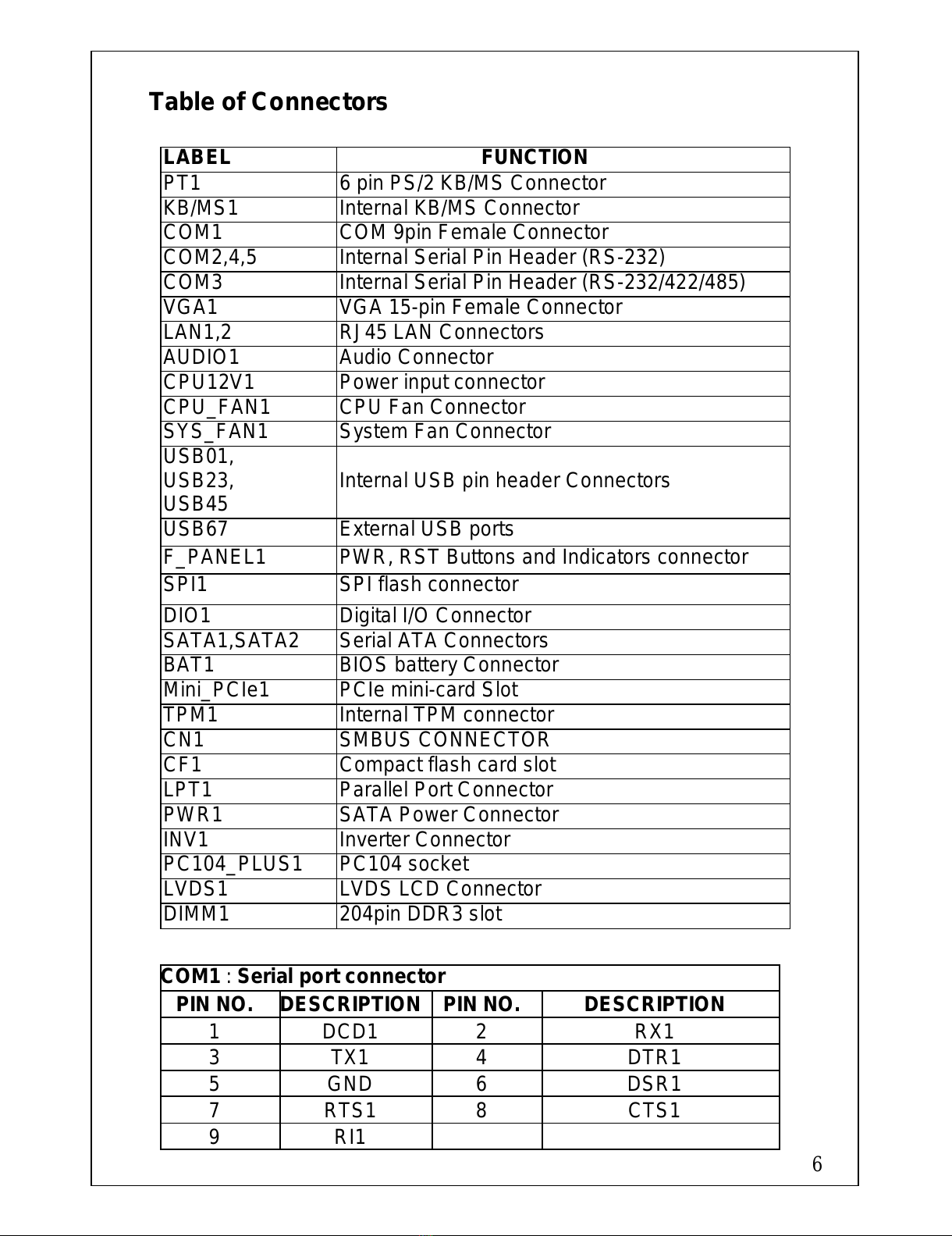
Table of Connectors
LABEL FUNCTION
PT1 6 pin PS/2 KB/MS Connector
KB/MS1 Internal KB/MS Connector
COM1 COM 9pin Female Connector
COM2,4,5 Internal Serial Pin Header (RS-232)
COM3 Internal Serial Pin Header (RS-232/422/485)
VGA1 VGA 15-pin Female Connector
LAN1,2 RJ45 LAN Connectors
AUDIO1 Audio Connector
CPU12V1 Power input connector
CPU_FAN1 CPU Fan Connector
SYS_FAN1 System Fan Connector
USB01,
USB23,
USB45 Internal USB pin header Connectors
USB67 External USB ports
F_PANEL1 PWR, RST Buttons and Indicators connector
SPI1 SPI flash connector
DIO1 Digital I/O Connector
SATA1,SATA2 Serial ATA Connectors
BAT1 BIOS battery Connector
Mini_PCIe1 PCIe mini-card Slot
TPM1 Internal TPM connector
CN1 SMBUS CONNECTOR
CF1 Compact flash card slot
LPT1 Parallel Port Connector
PWR1 SATA Power Connector
INV1 Inverter Connector
PC104_PLUS1 PC104 socket
LVDS1 LVDS LCD Connector
DIMM1 204pin DDR3 slot
COM1
: Serial port connector
PIN NO.
DESCRIPTION
PIN NO. DESCRIPTION
1 DCD1 2 RX1
3 TX1 4 DTR1
5 GND 6 DSR1
7 RTS1 8 CTS1
9 RI1
All manuals and user guides at all-guides.com

7
COM
2,COM4,COM5:
Serial port connector.(PIN HEADER 2*5,10PIN,P:2.0mm)
PIN NO
DESCRIPTION
PIN NO
DESCRIPTION
1 DCD 2 RX
3 TX 4 DTR
5 GND 6 DSR
7 RTS 8 CTS
9 RT
KB_MS1:
6-pin Mini-DIN Keyboard Connector
PIN NO. DESCRIPTION PIN NO. DESCRIPTION
1 VCC (+5V) 2 Mouse Data
3 Mouse Clock 4 Keyboard Data
5 Keyboard Clock 6 Keyboard GND
BAT1 :
Battery connector (WAFER 1*2PIN,2PIN,P:1.25MM)
PIN NO. DESCRIPTION PIN NO. DESCRIPTION
1 VBAT 2 GND
PT1
: Keyboard/Mouse Connector (MINIDIN JACK,6PIN,)
PIN NO.
DESCRIPTION
PIN NO
DESCRIPTION
1 L_KDAT 2 L_MDAT
3 GND 4 GND
5 VCC 6 L_KCLK
7 GND 8 L_MCLK
COM3 :
Serial port connector.(PIN HEADER 2*7,14PIN,P:2.0MM)
PIN
DESCRIPTION
PIN
DESCRIPTION
1 DCD3 2 DSR3
3 RXD3 4 RTS3
5 TXD3 6 CTS3
7 DTR3 8 RI2
9 GND 10 N/A
11
RS422 TX2
+/485
12 RS422 TX2-/485
13 RS422 RX2+ 14 RS422 RX2-
All manuals and user guides at all-guides.com

8
VGA1:
15-pin Female Connector
PIN NO.
DESCRIPTION
P
IN NO. DESCRIPTION
1 RED 2 GREEN
3 BLUE 4 NC
5 GND 6 GND
7 GND 8 GND
9 VCC 10 Display_ GND
11 NC 12 DDCDAT
13 HSYNC 14 VSYNC
15 DDCCLK
LAN1
,2: RJ45 LAN Connector
PIN NO.
DESCRIPTION PIN NO. DESCRIPTION
1 MDI0+ 8 MDI2+
2 MDI0- 9 MDI3-
3 MDI1+ 10 MDI3+
4 MDI1- 11 LED 100M LED
5 GND 12 MDI2-
6 GND 13 LAN Active
7 MDI2- 14 VCC3
USB0_1,USB2_3, USB4_5: USB Connector
PIN NO.
DESCRIPTION PIN NO.
DESCRIPTION
1 VCC (+5V) 5 DATA_P
2 GND 6 DATA_N
3 DATA_N 7 GND
4 DATA_P 8 VCC
USB
6
-
7
:
2
USB
Connector (USB PORT)
PIN NO.
DESCRIPTION PIN NO.
DESCRIPTION
1 VCC 2 DATA6_N
3 DATA6_P 4 GND
5 VCC 6 DATA7_N
7 DATA7_P 8 GND
9 VCC 10 DATA6_N
All manuals and user guides at all-guides.com
9
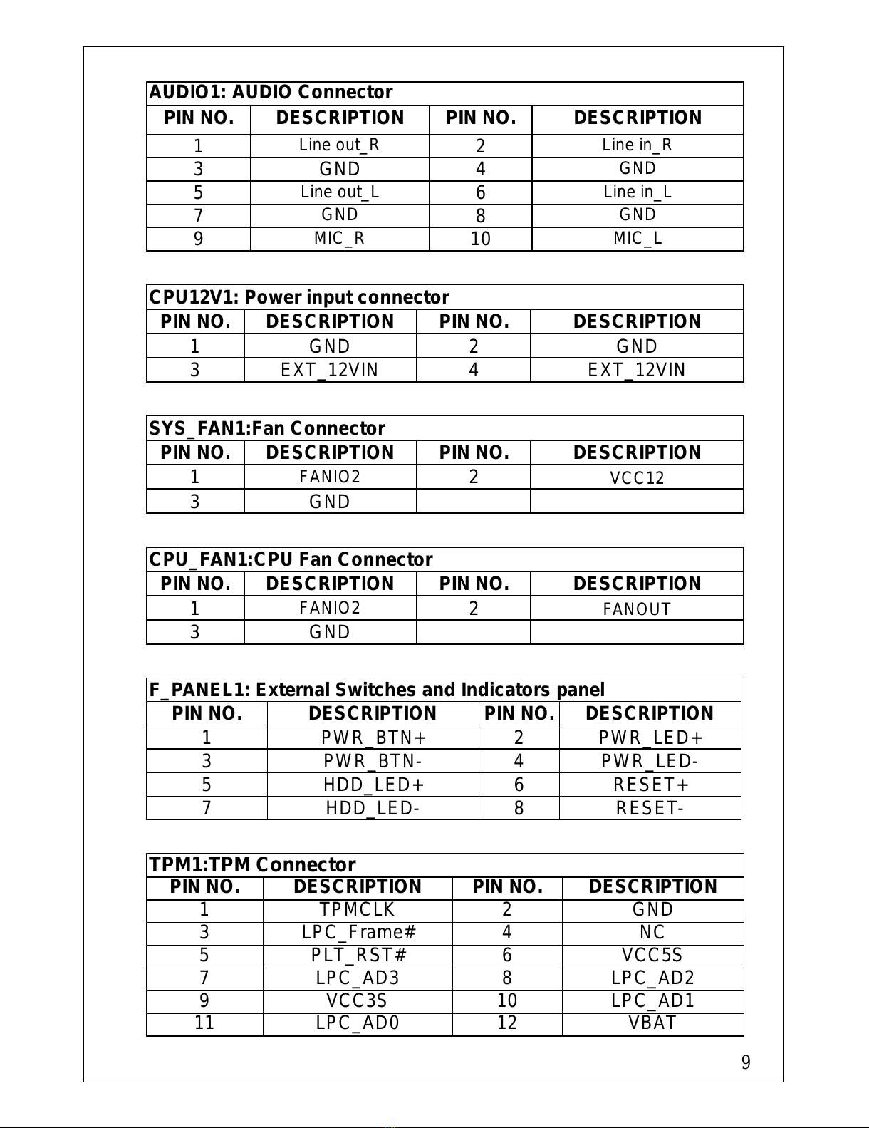
AUDIO1: AUDIO Connector
PIN NO.
DESCRIPTION PIN NO.
DESCRIPTION
1 Line out_R 2 Line in_R
3 GND 4 GND
5 Line out_L 6 Line in_L
7 GND 8 GND
9 MIC_R 10 MIC_L
CPU12V1: Power input connector
PIN NO.
DESCRIPTION PIN NO. DESCRIPTION
1 GND 2 GND
3 EXT_12VIN 4 EXT_12VIN
SYS_FAN1:Fan Connector
PIN NO.
DESCRIPTION PIN NO. DESCRIPTION
1 FANIO2 2 VCC12
3 GND
CPU_FAN1:CPU Fan Connector
PIN NO.
DESCRIPTION PIN NO. DESCRIPTION
1 FANIO2 2 FANOUT
3 GND
F_PANEL1: External Switches and Indicators panel
PIN NO. DESCRIPTION PIN NO.
DESCRIPTION
1 PWR_BTN+ 2 PWR_LED+
3 PWR_BTN- 4 PWR_LED-
5 HDD_LED+ 6 RESET+
7 HDD_LED- 8 RESET-
TPM1:TPM Connector
PIN NO. DESCRIPTION PIN NO. DESCRIPTION
1 TPMCLK 2 GND
3 LPC_Frame# 4 NC
5 PLT_RST# 6 VCC5S
7 LPC_AD3 8 LPC_AD2
9 VCC3S 10 LPC_AD1
11 LPC_AD0 12 VBAT
All manuals and user guides at all-guides.com

10
13 SMBCLK 14 SMBDATA
15 GND 16 INT_SERIRQ
17 GND 18 NC
19 VCC3S 20 LAD
DIO
1 : 10-pin Digital I/O Connector.
PIN NO DESCRIPTION PIN NO. DESCRIPTION
1 GND 2 VCC5S
3 OUTPUT3 4 OUTPUT2
5 OUTPUT1 6 OUTPUT0
7 INPUT3 8 INPUT2
9 INPUT1 10 INPUT0
CN1:SMBUS CONNECTOR
PIN NO. DESCRIPTION PIN NO. DESCRIPTION
1 GND 2 SDAT
3 SCLK 4 +5V
LVDS1 :
LVDS LCD Connector.
PIN NO.
DESCRIPTION PIN NO.
DESCRIPTION
1 GND 2 GND
3 LVDSA_DATA0+ 4 LVDSA_DATA0-
5 LVDSA_DATA1+ 6 LVDSA_DATA1-
7 LVDSA_DATA2+ 8 LVDSA_DATA2-
9 LVDSA_CLK 10 LVDSA_CLK-
11 NC 12 NC
13 GND 14 GND
15 L_DDC_DATA 16 L_DDC_CLK
17 VCC_LCD 18 VCC_LCD
19 VCC_LCD 20 VCC_LCD
SATA1
,SATA2: SATA Connectors
PIN NO. DESCRIPTION PIN NO. DESCRIPTION
1 GND 2 TXP
3 TXN 4 GND
5 RXN 6 RXP
7 GND
All manuals and user guides at all-guides.com
all-guides.com
11
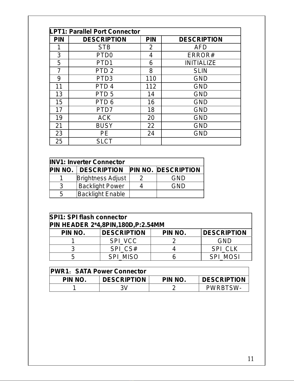
LPT1:
Parallel Port Connector
PIN
DESCRIPTION PIN
DESCRIPTION
1 STB 2 AFD
3 PTD0 4 ERROR#
5 PTD1 6 INITIALIZE
7 PTD 2 8 SLIN
9 PTD3 110
GND
11 PTD 4 112
GND
13 PTD 5 14 GND
15 PTD 6 16 GND
17 PTD7 18 GND
19 ACK 20 GND
21 BUSY 22 GND
23 PE 24 GND
25 SLCT
INV1
: Inverter Connector
PIN NO.
DESCRIPTION
PIN NO.
DESCRIPTION
1
Brightness Adjust
2 GND
3 Backlight Power
4 GND
5 Backlight Enable
SPI1
: SPI flash connector
PIN HEADER 2*4,8PIN,180D,P:2.54MM
PIN NO. DESCRIPTION
PIN NO. DESCRIPTION
1 SPI_VCC 2 GND
3 SPI_CS# 4 SPI_CLK
5 SPI_MISO 6 SPI_MOSI
PWR1:SATA Power Connector
PIN NO. DESCRIPTION
PIN NO. DESCRIPTION
1 3V 2 PWRBTSW-
All manuals and user guides at all-guides.com

12
Board Layout: Dimensions (Unit: MM)
All manuals and user guides at all-guides.com
13
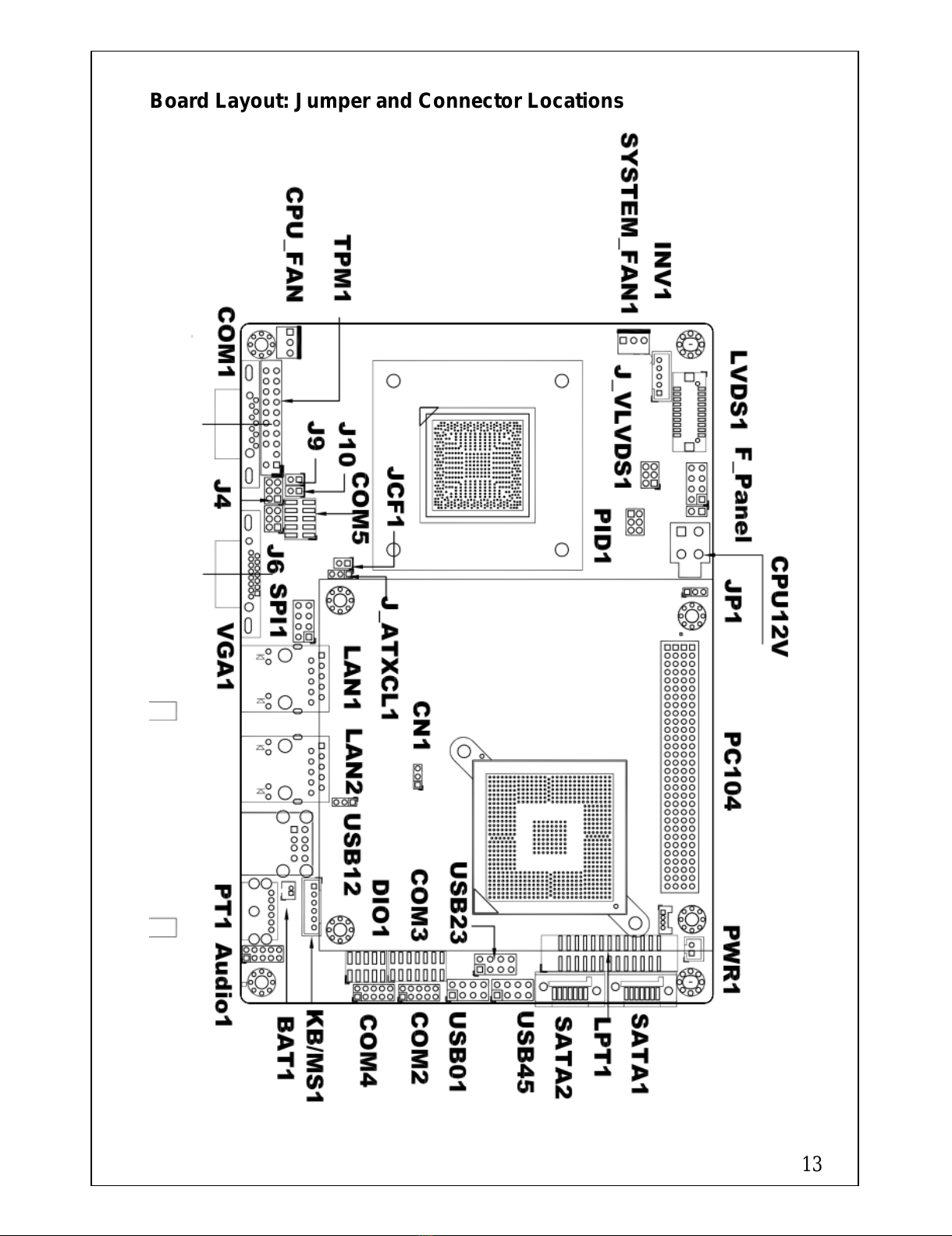
Board Layout: Jumper and Connector Locations
All manuals and user guides at all-guides.com

14
Bottom Side:
::
:
All manuals and user guides at all-guides.com
This manual suits for next models
3
Other Enoch Systems Motherboard manuals


