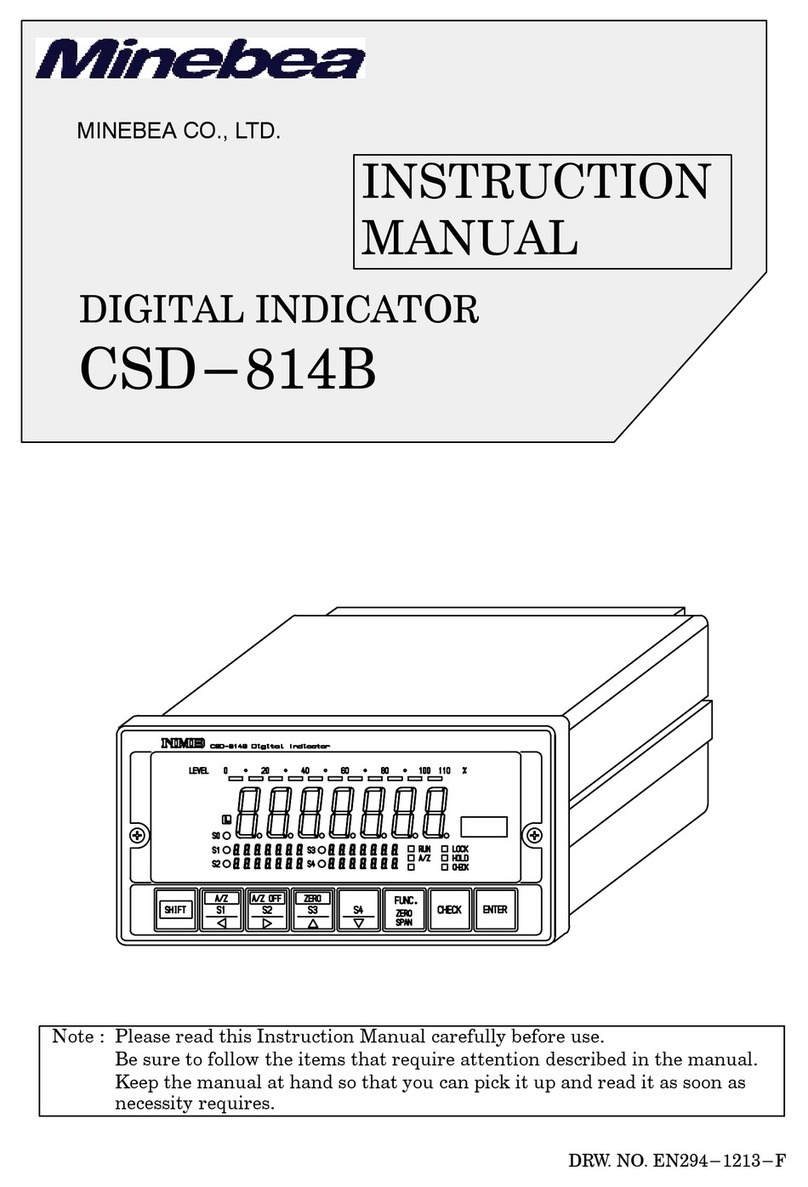
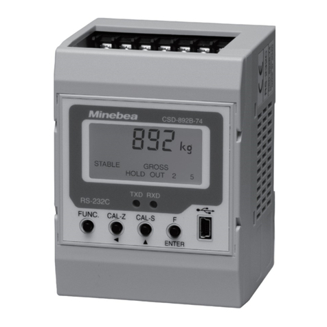
Minebea CSD-904-EX User manual

DIGITAL INDICATOR
CSD-904-EX
Instruction Manual
MINEBEA Co., Ltd.
Measuring Components Business Unit
EN294-1185-G

I
Forwards
Thank you very much for your purchasing Minebea’s Digital Indicator, model CSD-904-EX.
This manual explains the handling procedures and the notes when it would be used. Make use of it
properly after reading through the manual carefully.
Be sure to deliver the manual to the end user. Moreover, the end user should keep the manual at
hand after reading it over.
Marks and arrangements used in this manual
The following marks are attached to the explanation on the matters that indicate “Don’t do this.”,
“Take care” and “For reference”.
Be sure to read these items where these marks are attached.
Warning
Caution
Warning may cause injury or accident that may harm to the operator.
Don’t do these things described here.
It is a description when the occurrence only of assumption of danger by which the user owes injury when handling is mistaken, and material
damage is assumed.
Caution during operation and working.
Be sure to read the item to prevent malfunction.

II
For safe operation
Be sure to read this instruction manual before use.
1. Installation place
Caution
● Environmental temperature :-10 ℃ to 40 ℃
● Environmental humidity :Less than 85 %RH (Non condensing)
Warning
① Location where installation is not allowed.
● Do not locate the instrument in direct and/or high temperature area.
● Do not use the instrument in a high humid area.
● Do not install the instrument where there are vibrations and shocks.
● Do not use the instrument where there is excess of dusts and fine particles.
● Do not use the instrument where there are corrosive gas and salt and like that.
● Do not install the instrument where there is rapid change of temperature and humidity.
● Do not install the instrument near the devices that are magnetized or generate an electromagnetic field.
● Do not install the instrument where the instrument may be affected by radioactivity or radial rays.
● Avoid the location where chemical reaction may take place such as in a laboratory, or like that.
Use the instrument where the temperature/humidity specifies with the range as follows:
As it may cause an unexpected faulty in the instrument., don’t locate the instrument on the places as follows :

III
② Installation
Warning
Each dimensions of the instrument and required dimensions for the environmental spaces are as follows:
Side shape when the AC cable, the external control input plug or load cell connecting plug is attached.
Side shape when the BCD plug is attached.
● When installing the instrument, install as referring to the following figures and secure the space around the instrument.
Unit:mm
Front Side
Rear
Unit:mm
(55)
(48.5)
(50.3)
(
45.3
)
187
0
+1
92
Panel cut size
0
+1
192
96
141 (11)
20.2
186
91

IV
③ Applicable environment
Warning: The instrument may subject to use in a highly humid area or in full of powder dust.
In such a case, use the instrument by inserting the panel mount gasket attached between the control panel
(cabinet) and the main body.
By inserting the panel mount gasket, the front panel section becomes IP65 (International Protection Code) or
equivalent in dust-proof and water-proof construction.
Panel mounting attachment
Screw
Control board (Cabinet)
Panel mounting gasket
(Dust proof・Water proof)

V
2. Power supply
Warning
Warning
Caution
3. Application note
Caution
Caution
Caution
Caution
Caution
Be sure to check that the power supply is off in connecting each cable. If the work is done while the power is on, there may have the case that
electric shock to the operator or even may have damage to the instrument.
Before supplying the power, check that the indication of power supply voltage/specifications for the instrument and the power going to supply
should be the same. If they are not equal, contact with Minebea. If you use the instrument without checking them, it may cause a damage in the
instrument or electric shock to the operator.
Earth wire should be grounded securely.
When earth wire is not connected, it may cause a malfunction of the instrument or electric shock to the operator.
Before using a new instrument or exchanging the strain gage applied transducer for a new one, be sure to make calibration. If calibration will not
be made, the correct measuring results may not be obtained nor which may cause malfunction in the instrument and there may exist damage
in peripheral equipment. Besides, even though calibration has been made, there may occur the similar case when the results are not correct, so
make calibration, again.
When change of setting is made carelessly on the instrument during measurement, the correct measuring results may not be obtained and it
may cause malfunction in the instrument and even have the possibility of damage in peripheral instruments.
In case of using the instrument, check that the connections are executed properly. If not connected properly, the correct measuring result will
not be obtained, nor it may cause malfunctions of the instrument, damage to the peripheral equipment or even more serious accidents.
Do not shock the instrument such as throwing something on it.
If neglected, it may cause destruction of the parts and damage to the electrical circuits.
Do not remove the case cover of the instrument, nor peel off the panel sheet nor take the instrument into pieces. If neglected, it may cause a
damage to the case and the panel sheet and even have the possibility of damage to resist to environments or operational performances.
At the time of shipment from the factory, the instrument has been plated with a clear sheet on the panel sheet for protective purpose.
In case of application, use the instrument after removing the clear sheet first.
Do not push the panel sheet on the instrument with the excessive strong force nor push it with sharp edge object such as a driver. If
neglected, it may cause damage to the panel switch and even have the possibility of damage to resist to environments or operational
performances.

VI
History of revision
Date Instruction manual No. Details of revised point
2003/03 DRW. NO.EN294-1185 First Version Ver.2.000
2003/04 DRW. NO.EN294-1185A
Due to ECN NO. FN03-02048.
*Changed the “minimum scale “ to “scale interval”.
*Changed the “meter “ to “measuring section”.
*Changed the “measurement display “ to “load display”
*In the section 6-9-5,changed the “minimum scale” to “scale
interval in calibration”
*Change the “OVR.” to “OVER” in the section 13-2-8 and 15-3.
*Corrected the “ID No.” to “Address” in 13-3-12.
*Added “Sending data: binary code BCD” on the table in 12-1.
2003/08 DRW. NO.EN294-1185B Due to ECN NO. FN03-02107.
– Correction –
13-3-13. write “Contents” instead of Japanese
2004/11 DRW. NO.EN294-1185C
Due to ECN No.FN04-02169
・Correction of the error/mistake in the contents.
・Correction of a gravity acceleration setting value
Nov. 2005 DRW. NO.EN294-1185D
Due to ECN No.FN05-02135
*Add the clause “When this is used in Japan domestic, the voltage
that exceeds AC125 V cannot be supplied by the limitation of
“Electrical Appliance and Material Safety Law”.
May. 2010 DRW. NO.EN294-1185E
Due to ECN No.FN10-01019A
- Addition -
Panel mounting gasket is added.
Oct. 2010 DRW. NO.EN294-1185F
Due to ECN No.FN10-02140
- Change -
Minebea logo is changed.
Jan. 2011 DRW. NO.EN294-1185G
Due to ECN NO.FN11-02001A
- Correction -
13-3-10. “DE-9S-N (JAE)”
to “DE-9S-NR by JAE or equivalent.”
Due to ECN No.FN11-02016
ROM Ver.3.100 or lator.
- Addition –
7-2. ”Function of the function date”
Key lock F-08 is added to the table.
8-4. “Key lock function” is added.
8-4-1.”Key lock” is added.
19. “Setting table for functions”
F-08 is added to the table.
Update of Index.

1
Index
Forwards ........................................................................................................................................................................I
Marks and arrangements used in this manual .....................................................................................................I
For safe operation......................................................................................................................................................II
1. Installation place............................................................................................................ II
2. Power supply...................................................................................................................V
3. Application note ..............................................................................................................V
History of revision....................................................................................................................................................VI
1. Name and function of each point ......................................................................................................................1
1-1. Front panel..................................................................................................................... 1
1-2. Rear panel ...................................................................................................................... 3
2. Connecting method ...............................................................................................................................................4
2-1. Notes concerning to the connecting wires......................................................................... 4
2-2. Connection with the load cell........................................................................................... 4
2-3. Connection of the external control input .......................................................................... 6
2-4. Connection of the serial interface (S-I/F).......................................................................... 7
2-5. Connection of the power supply and ground..................................................................... 8
3. Operation .................................................................................................................................................................9
3-1. Changeover of mode........................................................................................................ 9
4. Calibration............................................................................................................................................................. 11
4-1. Set items required in the calibration...............................................................................11
4-2. Procedure set if necessary after calibration.....................................................................11
4-3. Calibration procedures.................................................................................................. 12
4-4. Fine adjustment of zero and span.................................................................................. 18
4-5. Digital linearize ............................................................................................................ 21
4-6. Calibration only of zero point ........................................................................................ 24
4-7. LOCK of calibration...................................................................................................... 26
5. C function mode.................................................................................................................................................. 27
5-1. Setting method of C function data ................................................................................. 27
5-2. Function of C function data ........................................................................................... 28

2
6. Various functions by C function data ........................................................................................................... 30
6-1. Setting of decimal point display position ........................................................................30
6-2. Condition of over display ( or display)................................................................30
6-3. Setting of the unit..........................................................................................................30
6-4. Zero set .........................................................................................................................30
6-5. Zero tracking.................................................................................................................31
6-6. Power on zero ................................................................................................................32
6-7. Tare weight cancellation ................................................................................................32
6-8. Gravity acceleration compensation.................................................................................33
6-9. Automatic range switch .................................................................................................35
6-10. Setting of the stability detection time width in calibration ............................................36
6-11. Digital linearizer clear .................................................................................................36
6-12. Memory clear...............................................................................................................36
7. Function mode..................................................................................................................................................... 37
7-1. Setting method of the function mode ..............................................................................37
7-2. Function of the function data .........................................................................................38
8. Various functions by function data................................................................................................................ 41
8-1. Digital filter ..................................................................................................................41
8-2. Display frequency..........................................................................................................41
8-3. Stabilization filter..........................................................................................................41
8-4. Key lock function ...........................................................................................................43
8-5. Stability detection..........................................................................................................43
8-6. Input of the fixed tare weight cancellation......................................................................44
8-7. Automatic printing ........................................................................................................45
8-8. Accumulation.................................................................................................................45
8-9. Setting of the external control input operation ...............................................................47
8-10. Memory clear...............................................................................................................47
9. Record place of set data.................................................................................................................................. 48
9-1. Data recorded in RAM ...................................................................................................48
9-2. Data recorded in EEPROM ............................................................................................48

3
10. Check mode ....................................................................................................................................................... 49
10-1. Setting method of Check mode..................................................................................... 49
10-2. Confirmation of ROM version ...................................................................................... 50
10-3. Confirmation of external control input......................................................................... 50
10-4. Confirmation of contact output .................................................................................... 51
10-5. Confirmation of load cell output voltage....................................................................... 51
10-6. Confirmation of BCD output (When BCD output is applied.) ........................................ 52
10-7. Confirmation of analog output (When the analog output is applied.)............................. 52
11. Comparator ........................................................................................................................................................ 53
11-1. Comparison operation of comparator............................................................................ 53
11-2. Target of comparator comparison operation.................................................................. 53
11-3. Upper/lower limit comparison mode............................................................................. 53
11-4. Weigh in/out mode....................................................................................................... 57
12. Serial interface (S-I/F)................................................................................................................................. 61
12-1. Specification of interface.............................................................................................. 61
12-2. Data format ................................................................................................................ 61
12-3. Explanation of format data.......................................................................................... 62
12-4. Explanation of output type .......................................................................................... 62
13. Options................................................................................................................................................................ 63
13-1. Analog output .............................................................................................................63
13-2. BCD output................................................................................................................. 67
13-3. RS-232C and RS-422/485 interface .............................................................................. 71
13-4. Contact output............................................................................................................84
13-5. Power supply voltage................................................................................................... 85
14. Trouble shooting............................................................................................................................................... 86
14-1. Execute trouble shooting ............................................................................................. 86
15. Specifications .................................................................................................................................................... 98

15-1. Specifications for analog.............................................................................................. 98
15-2. Specifications for digital .............................................................................................. 98
15-3. Interface ..................................................................................................................... 98

4
15-4. General specifications ..................................................................................................99
15-5. Specification at the shipment .....................................................................................100
15-6. Accessories.................................................................................................................100
16. Error display..................................................................................................................................................... 101
17. Warranty............................................................................................................................................................ 102
17-1. Warranty................................................................................................................... 102
17-2. Repair .......................................................................................................................102
18. Character's pattern for display................................................................................................................... 103
19. Setting table for functions ...........................................................................................................................104

1
1. Name and function of each point
1-1. Front panel
① Unit display section
The set measuring unit is displayed.
“○” lights on at the unit display section at the stand-by condition(The load display has been turned off
while energized.).
② Load display section
It displays “Gross/Net value”, “Over” and “Error”.
Also it displays the condition or the setting value in proceeding the various setting.
③ Condition display section
It displays the condition of CSD-904-EX.
ACCUM. It lights on when the accumulation data is made.
Also, it blinks when the accumulation data is displayed.
The load value and the accumulated display are switched by key.
MD It lights on when the measured data is steady.
PT It blinks while setting a fixed tare weight cancellation.
It lights on when a fixed tare weight cancellation is set.
TARE It lights on when the tare weight cancellation is executed.
GROSS It lights on when the load display is gross value.
NET It lights on when the load display is net value.
ZERO It lights on the load value of gross or net value is a zero, and within ±1/4 of
a scales interval.
④ Judgement display section
It displays the comparison result of the comparator function.
⑤ key
This key turns the display on and off. When the display is turning off, the electric power is supplied to
the inside of the indicator and the measuring section. The display becomes the stand-by condition at
the time of turning off.
① Unit display section
② Load display section
④ Judgement display section
③ Condition display section
⑤ Key for ON/OFF
⑥ Key for setting
⑦ Key for accumulation
⑧ Key for the set of tare weight
⑫ Key for printing
⑪ Key for zero set
⑩ Key for net or gross weight
⑨ Key for tare weight cancellation

2
⑥ key
It is switched to the accumulation display, and also to the previous state by which the status of each
mode is set.
⑦ key
It is used for the load value to accumulate, and also it carries up the set digit when the value is set.
⑧ key
It is used when the setting of the fixed tare weight cancellation is executed.
And also it carries down the set digit when the value is set.
⑨ key
The tare weight cancellation is executed.
And one value of the selected digit is raised when the value is set.
⑩ key
It switches the gross value and net value of the displayed data.
And one value of the selected digit is lowered when the value is set.
⑪ key
It memorizes a present load value as a zero point, and makes the display a zero.
⑫ key
It outputs the printed data. Moreover, it decides various data entries, and memorizes the set value in
an internal memory.

3
1-2. Rear panel
① Power supply socket
Connecting the AC cable regularly attached to this point, the power supply voltage is supplied.
② Fuse holder
The fuse of the specified capacity is installed.
③ Optional products attaching portion 1
One point of either the BCD output, RS-232C, RS-422/485, the analog electric current output or the
analog voltage output is installed.
④ Optional products attaching portion 2
The contact output is installed.
⑤ Connector for the external control input
It is an input connector to control the function of this unit with outside contact point or open collector.
⑥ Output terminals for serial interface
It connects with the printer or the external display unit.
⑦ Connector for load cell
It connects with the signal wires from the measuring section (load cell).
⑧ Calibration LOCK switch section
Calibration LOCK switch can be operated by removing the cover.
①Power supply socket
③Optional products
attaching portion 1
②Fuse holder ⑦Connector for load cell
⑥Output terminal for
serial interface
⑤Connector for external
control input
④Optional products
attaching portion 2
⑧Calibration LOCK switch section

4
2. Connecting method
2-1. Notes concerning to the connecting wires
● Be sure to set the power supply to OFF, when the connection will be made.
● Please do not put the plug of the AC power supply until the installation is completed.
There is no switch which switches power supply ON/OFF in the main body.
● Please separate the cable connected with the main body from the power supply line and noise source of
control I/O, etc., as much as possible.
● Conduit wiring should be the type of exclusive one, and avoid using with another line together.
● The grounding wire should be connected. Grounding should be the D class with single earth.
Please do not share with the grounding and the power supply system.
Please connect the grounding via the attached AC cable.
● Please use the shielded cable for the connection with the external control input and the contact output,
and also connect the shield with the shield terminal or the main body.
2-2. Connection with the load cell
Please connect the plug attached as a load cell connector with the receptacle in the rear panel to connect with
the load cell. Suitable plug : NJC-207-PF(by Nanahoshi) or equivalent.
① When the connecting cable is 6 wires method
② When the connecting cable is 4 wires method
The connection between the second of sensing input +/connector and the third of the sensing input -/connector should be short-circuited
near the main body of the load cell. It will not work as the 6 wires method when the short-circuit is made in the load cell connector.
In case of using with 4 wires method, the connection between No.1 - No.2 and No.3 – No.4 in the connector should be short-circuited.
When No.2 connectors and No.3 are used while opened, CSD-904-EX does not work normal operation.
Load cell Sensing input +
Load cell connecto
r
Sensing input -
Load cell input -
Load cell input +
Shield
Load cell
Load cell input +
Load cell input -
Load cell exciting +
Load cell exciting -
Load cell connecto
r
Load cell exciting +
Shield
Load cell exciting -

5
③ When you connect the load cell in parallel
The hopper scale, the track scale, etc., have the case to connect the several pieces of the load cell in
parallel. The parallel connection can be easily done by using optional SB-310 and SB-320 (Summing
type junction box).
Load cell connecto
r

6
2-3. Connection of the external control input
The function can be controlled from the outside with the “INPUT” connector in the rear panel.
It is executed by shorting each pin and the COM pin with a contact point or an open collector after wiring for
the connector.
Pin No. Function No. Setting value and details
0 Operation OFF
1 The same operation as key
2 The same operation as key
3 The same operation as key
4 The same operation as key
5 The same operation as key
6 The same operation as key
7 The same operation as key
8 The same operation as key
9 Display the net weight
(Effective during the measurement mode.)
1 F-60
INPUT1 function
10 Display the accumulated value
(Effective during the measurement mode.)
2 COM pin of INPUT1~7
3 F-61 INPUT2 function Selectable as well as F-60
4 F-62 INPUT3 function Selectable as well as F-60
5 F-63 INPUT4 function Selectable as well as F-60
6 F-64 INPUT5 function Selectable as well as F-60
7 F-65 INPUT6 function Selectable as well as F-60
8 F-66 INPUT7 function Selectable as well as F-60
Connect
or case Shield connection
Suitable plug : TCP0586-71-5201(by Hoshiden) or equivalent good.
● For the connections with external control inputs, be sure to apply shielded cable, and the shield should be connected with the connector
case. If not connected, it may cause malfunction due to the effects from external noises and so on.
● When “1 to 8” is selected in the setting of function F-60 to 66, each external control input becomes the same operation as the key input
operation.
● After about 100 ms or more is short-circuited, the operation is executed as for the input signal.
● Only the changeover of the net amount display and the changeover function of the accumulated display are the level input.
Other than them are pulse input and become effective once at the pulse width of 100 ms or more.
● Common of the COM of the external control input (two pins) and serial interface circuits is common.
INPUT
Layout of INPUT connector pin
CSD-904-EX internal e
q
uivalent circuit
or

7
2-4. Connection of the serial interface (S-I/F)
It is a two-wire method serial interface to connect a printer and an external indicator, etc.
● There are M250 printer etc. made by Unipulse as an equipment for the serial interface.
● The cable must use two wires shielded cable as much as possible. Please connect the shield to F.G. terminal.
Please make the cable in the twist when you do not use the shielded wire.
(The length of the cable is within 100 m for shielded wire, and within 20 m for unshielded wire.)
● Equipment for the serial interface can be connected up to three units in parallel. (The maximum output current Approx.DC20 mA)
● Common of the COM of the external control input(two pins) and the serial interface circuit is common.
● Internal circuit is isolated through photo-coupler.
CSD-904-EX internal
equivalent circuit
Equipment for
serial interface

8
2-5. Connection of the power supply and ground
Please insert the attached AC cable into the socket of power supply in the rear panel.
Plugs of the AC cable are three pins, and pins round-shaped at the center are the ground terminal.
It is inserted in the power supply outlet in the predetermined power requirement.
Please use the attached adapter for ground when the ground terminal is not exist in the outlet.
Power supply voltage
AC100 V (Permissible variable range AC85 V to AC110 V)
Power supply frequency
50/60 Hz
Caution
● Connections with the power supply and the earth should be made securely according to the above figures and also within the rated capacity
of the instrument.
● Attached AC cable is to be used for AC125 V power supply. When you will use the power supply of AC200 V or AC240 V, please prepare
the cable for AC250 V power supply separately.
● When this is used in Japan domestic, the voltage that exceeds AC125 V cannot be supplied by the limitation of “Electrical Appliance and
<ateroal Safety Law”.
● Grounding should be the D class with single earth. If neglected, it may cause an unexpected malfunction due to the effects of noise from
other equipment.
Rear panel
Adapter for the ground
Code of
power supply
Socket of power supply

9
3. Operation
3-1. Changeover of mode
This unit has various modes according to the operating situation.
Proceed the changeover of the mode by the key operation.
● When the load cell output exceeds ±10 % of weighting by the power on zero function after checking the display, the display becomes the
error indication of “ ”. At this time, if the key is pressed, the display compulsorily becomes a load display. Refer to the
paragraph 6-6. Power on zero.
Power ON
Display check
(All lights on)
display of
Measurement mode
(Display measuring value)
Stand-by condition
(Lights off the measuring value display)
Set mode
①Refer to the function mode
②Refer to the C function mode
Measurement mode
(Display accumulated value)
⑤Refer to the comparator mode
+
+
③Refer to the calibration
mode
④Refer to the check mode
display of
display of
display of
Table of contents
Other Minebea Measuring Instrument manuals

Minebea
Minebea TMD-100 User manual

Minebea
Minebea CSD-401 User manual

Minebea
Minebea CSD-801 User manual

Minebea
Minebea CSD-903-73 User manual

Minebea
Minebea CSD-814B User manual

Minebea
Minebea CSD-892B-07-25 User manual

Minebea
Minebea CSD-709 User manual

Minebea
Minebea CSD-891B User manual

Minebea
Minebea CSD-581-74 User manual

Minebea
Minebea MIS-202-PT User manual
Popular Measuring Instrument manuals by other brands

WIKA
WIKA mensor 9476 operating instructions

Thermo Electron
Thermo Electron ELECTRA Operator's manual

Calculated Industries
Calculated Industries Scale Master Classic user guide

Tektronix
Tektronix TLA7N Series Service manual

Dewetron
Dewetron TRIONet Technical reference manual

Triplett
Triplett GSM350 manual