eNovates Single Wallbox User manual

Single Wallbox
Installation manual
SWB_4xx_22_T2
SWB_4xx_22_C7
SWB_4xx_22_T2S
SWB_4xx_22_T2SE
English

To access the Single Wallbox Installation Manual
please scan the QR code or use the link
https://www.enovates.com/manual-installation-manual/
To access the Pedestal Installation Manual
please scan the QR code or use the link
https://www.enovates.com/manual-pedestal-installation/
To access the Single Wallbox User Manual
please scan the QR code or use the link
https://www.enovates.com/manual-user-manual/
To access the Single Wallbox Acessories Manual
please scan the QR code or use the link
https://www.enovates.com/manual-accessoire-manuals/

CONTENTS
Contents1. Safety instructions................................................................. 5
1.1. Purpose..................................................................... 5
1.2. Safety terminology...................................................... 5
2. Technical specifications........................................................... 9
3. Installation supplies.............................................................. 11
3.1. Box content.............................................................. 11
3.2. Accessories...............................................................12
3.3. Required tools...........................................................13
4. Installation requirements.......................................................14
4.1. Installer specifications................................................14
4.2. General cable specifications........................................ 14
4.3. Power cord specifications............................................14
4.4. Grounding specifications.............................................15
4.5. Required nominal input voltage................................... 15
4.6. Electrical protection specifications................................16
5. Wall mounting......................................................................17
6. Check before configuration.................................................... 24
7. How to configure.................................................................. 25
8. Final note............................................................................ 26
9. Support...............................................................................26
10. Abbreviations..................................................................... 27
11. Software............................................................................29
3


1. SAFETY INSTRUCTIONS
1.1. Purpose
Safety instructions are provided below in order to ensure safe, long-
term use of the product. Failure to comply with the instructions
and general safety guidelines for electrical systems may lead to an
electric shock, fire hazard, damage, malfunction, injury and/or death.
Read the safety instructions in this document before installing and
using the product.
1.2. Safety terminology
Danger texts provide important
information to avoid situations with a
high chance to cause severe malfunction,
damage, injuries or death.
Warning texts provide important
information to avoid situations with a
significant chance to cause malfunction,
damage, injuries or death.
Caution texts provide important
information to avoid situations that
may cause some degree of malfunction,
damage or injuries.
5

• Do not let the product be used by children, or individuals who
cannot assess the risks associated with unintended product use.
Children in the vicinity must be supervised by adults while the
product is in use.
• Do not have the product serviced by non-qualified personnel in
order to avoid the risk of serious injury from electric shock or
damage to the product. None of the product’s parts are intended
to be serviced by users. Do not attempt to disassemble, tamper
with, or modify the product. If the product requires servicing,
repair or relocation, contact a qualified electrician to perform
these operations.
• If an accident has occurred or a hazardous situation has
developed with regard to the product, have a certified electrician
immediately disconnect the product’s electrical supply.
• Do not use the product if one or more of its components may
have become damaged or compromised.
• Always make sure the product is not submerged in water, and
is not located near water. Do not handle the product with wet
hands, and make sure no liquid is sprayed on it or comes into
contact with it. Store the charging cable in the socket to prevent
unnecessary exposure to contamination or moisture. Handling the
product or its components while conductive liquids are present
may cause an electric shock with the risk of serious injury or
death.
• Do not use or install the product in the vicinity of explosive,
volatile, combustible or highly flammable substances. Note that
some electric vehicles release hazardous or explosive gasses
when charging, which may cause an explosion with the risk of
serious injury or death. Refer to the vehicle’s manual to check
if this is the case, and follow the instructions it specifies before
choosing the location of the product.
6

• The product must be grounded through a permanent wiring
system or grounding conductor.
• Disconnect input power at the circuit breaker before installing,
cleaning, removing or relocating the product.
• The product should be used to charge Mode 3 compatible
electric vehicles only. Check the vehicle’s compatibility using the
information in the vehicle manual.
• Avoid using a private power generator, adapters, conversion
adapters or cord extensions with the product. The introduction of
accessories not prescribed for the product may create technical
incompatibilities that can cause malfunction or damage, and
result in injury or death.
• Do not let the product and charging cable come into contact with
heat sources. High temperatures may impair functionality, cause
damage or cause hazards.
• Damage to the product may cause injury or death. Respect the
product’s operating parameters and technical specifications, and
make sure damage is not inflicted or allowed to accumulate on
the product. Do not use the product if it fails to operate normally
or appears cracked, frayed, broken or otherwise damaged. If you
suspect the product may have been damaged, have it checked by
a qualified electrician as soon as possible.
• Take care not to apply force or pressure to any part of the product
or to damage it with sharp objects or impacts.
• Use of the product may interfere with the proper functioning
of medical or implantable electronic devices in the user, such
as a pacemaker or defibrillator. The user should check with the
manufacturer of such electronic devices whether electric charging
may affect such a device before using the product.
7

• Installing and/or testing the product incorrectly may result in
damage to the product and/or a connected vehicle’s battery.
Such damage is excluded from the vehicle and charging product’s
warranties.
• The charging cable must be completely unwound and overlapping
loops must be avoided before charging to prevent overheating,
which may damage the product.
• Do not put fingers or objects in the socket or any other exposed
part of the product, as doing this may cause injury or damage.
• Keep (electro)magnetic devices away from the product, as their
use in the vicinity of the product may negatively affect the
product’s functionality, even to the point of causing damage to the
product.
• Use the product only in temperatures within its operating range of
-30°C to 50°C.
• Only transport and store the product in its original packaging.
Do not subject the product to strong force, impact, pull, twist,
tangle or drag and do not step on any part of the product. If the
product is damaged in transport, while it was not transported in
its original packaging, no damage liability can be accepted.
• Store the product in a dry environment and within the
temperature range provided in the technical specifications.
8

2. TECHNICAL SPECIFICATIONS
Residential & Fleet Professional
Charging Mode Mode 3 (IEC 61851-1ed.
3) ISO-15118
Mode 3 (IEC 61851-1ed.
3) ISO 15118
Charge Control RFID (IEC 14443 A/
B, ISO 15693) Plug &
Charge (ISO-15118-2)
RFID (IEC 14443 A/
B, ISO 15693) Plug &
Charge (ISO-15118-2)
Connectivity BLE 5.X
Wifi Client Mode
Ethernet (2x LAN,
bridged)
BLE 5.Xw
Wifi (AP & Client)
Ethernet (WAN + LAN,
router)
2G / 4G / LTE
Multi-charge
(Parking Lot)
Satellite Main Charger/ Satellite*
Backend Protocol OCPP 1.6J
OCPP 2.0
OCPP 1.6J
OCPP 2.0
Metering MID meter MID meter
Load Balancing Supported via optional
hardware
Supported via optional
hardware
HMI BLE app BLE app
Options Broken PEN
Detection
BiDirectional Charging
(V2G AC)
HEMS Integration
(EEBus)
Broken PEN
Detection
BiDirectional Charging
(V2G AC)
HEMS Integration
(EEBus)
* A network with one main charger and one or multiple satellites acts as a charging hub. In
this setup, satellite charge points are dependent on a main charger. The main charging
station handles the loadbalancing in the charging hub.
Electrical Properties
Supply network system AC
Electric connection
method
Permanently connected
Protective class Class I equipment
Voltage Rating 1x230V+N (50Hz)
3x400V+N (50Hz)
3x230V (50Hz)
Current Rating 32A
Rated impulse voltage 4kV
9

Electrical Properties
Max Charging Power 7.4kW (single phase)
22kW (triphase)
Charging socket AC–Type2 socket
Optional: T2S, T2SE
Cable plug Cable (7m) with AC-Type2 plug
Installation wiring 0.75 .. 10mm²
Earth Leakage Detection DC 6mA (included)
Compliancy The products described above are in conformity with
the relevant Union harmonization legislation:
-Low Voltage Directive LVD (2014/35/EU and
changes)
-Electromagnetic Compatibility EMC Directive
(2014/30/EU and changes)
-Radio Equipment and repealing Directive (2014/53/
EU)
-Waste electrical and electronic equipment WEEE
directive (2012/19/EU)
-Registration, Evaluation, Authorization and
Restriction of Chemicals REACH directive (No
1907/2006)
-RoHS directive (2002/95/EC)
-RoHS 2 Directive (2011/65/EU)
and are compliant with the following standards:
-IEC 61851-1:2017
-IEC 61851-21-2:2018
-IEC 62196
-IEC 60529:1989 + A1: 1999 + A2:2013
-IEC 61439-7:2018
-OCPP1.6 Full incl. Security
-EV-Ready 1.4G1
-ZE-Ready 1.4G1
Physical Properties
Access Locations with non-restricted access
Dimensions (W x H x D) 248 x 426 x 120 (T2 or C7)
248 x 426 x 165 (T2S or T2SE)
Weight (kg) 3.5 - 5.0 kg
Enclosure rating IK10 (IEC 62262)
IP54 (IEC 60529)
Operating Temperature -30°C … +50°C
Humidity Max 95% (non condensing)
10

Physical Properties
Mounting Wall mount (included)
Single side pedestal (optional)
Double side pedestal (optional)
Warranty 2 years
3. INSTALLATION SUPPLIES
Not all the necessary tools for installation are delivered with the
product.
Before you start, please check that all tools and components,
required for an easy installation, are available.
3.1. Box content
12
3
4
56789
11
10
12
# Description Amount
1 Charger unit (T2 version or C7 version with fixed cable) x1
2 Cover (contains socket lid) x1
Cable block x1
3Cable bridge x1
11

# Description Amount
4 Wall bracket x1
5 Security screw M4x8 (Torque 1.2Nm) x1
6 Screws M5x14 (Torque 1.2Nm) x4
7 Screws M5x16 (Torque 1.2Nm) x2
8 Screws M6x14 (Torque 1.2Nm) x2
9 Screws 6x30 (Torx T25) x3
10 Plugs 8mm x3
11 Installation Manual x1
12 C sticker (hexagonal) x1
3.2. Accessories
#Can be additionally purchased Residential
& Fleet
Professional
1 eDSBI x x
2 eDSBIII x x
3 eDLB x
4 eDP1B: Dynamic P1 Balancer x x
5 External Coil set x x
6 Single Side Pedestal x x
7 Double Side Pedestal x x
8 Pedestal Anchor
(flat for solid soil)
x x
Compatible external tools Residential
& Fleet
Professional
Potential-free on/off peak contact x x
Shunt device x x
12
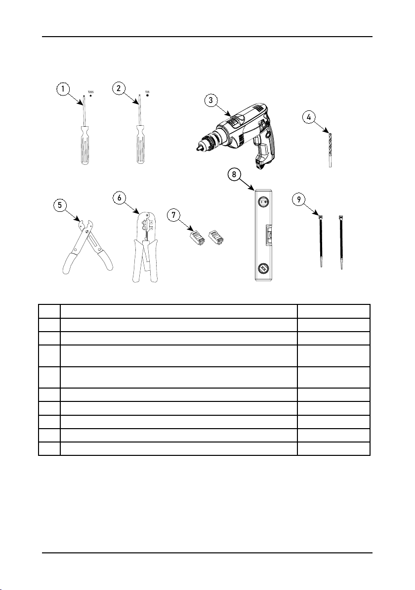
3.3. Required tools
T20S T25
12
3
4
5
6
7
9
8
# Description Amount
1 Torx screwdriver T20S x1
2 Torx screwdriver T25 x1
3 Drill for pedestal mounting
(suited to mounting surface) x1
4 Hand drill 8mm for wall mounting
(suited to mounting surface) x1
5 Cable stripper x1
6 Ethernet RJ45 cable crimper x1
7 Ethernet connector RJ45 for cable crimping x2*
8 Spirit level tool x1
9 Tie wraps x2
* When installing a charging hub, 1 or 2 ethernet connectors are used for each charge point.
This depends if charging hub is configured as a daisy chain or a star.
13

4. INSTALLATION REQUIREMENTS
4.1. Installer specifications
Only authorized technicians should install and maintain the product.
The technician should conform to the following qualifications:
• safety measures as well as the parts of this manual that relate to
the installation of the product;
• The technician should be aware of and comply with all applicable
local, national and international laws and regulations;
• The technician should be capable of acknowledging the potential
hazards of the product and take the necessary precautions to
protect people and property from hazard damage.
4.2. General cable specifications
The product requires a proper power cord. An ethernet cable is
recommended (not required) to connect the charge point with the
internet. Wifi and 4G (only professional) are also possible to connect
the charge point with the internet. The ethernet cable is not to be
used underground unless through a holding tube or reinforced (STP)
cable in order to prevent corrosion by moisture or rupture by ground
shifts.
Insofar as is possible, the cables should already be present and ready
to connect to the product at the start of the product installation
procedure. Use of sheathed cables is recommended when running
cables underground. Do note that the RJ45 connectors should be
connected only after feeding the cable through the grommet into the
product.
Always use shielded ethernet cable when installing.
4.3. Power cord specifications
The electrician should select the type and dimensions of the power
cord and safety components as appropriate for the installation
environment and situation, compliant with local regulations.
14
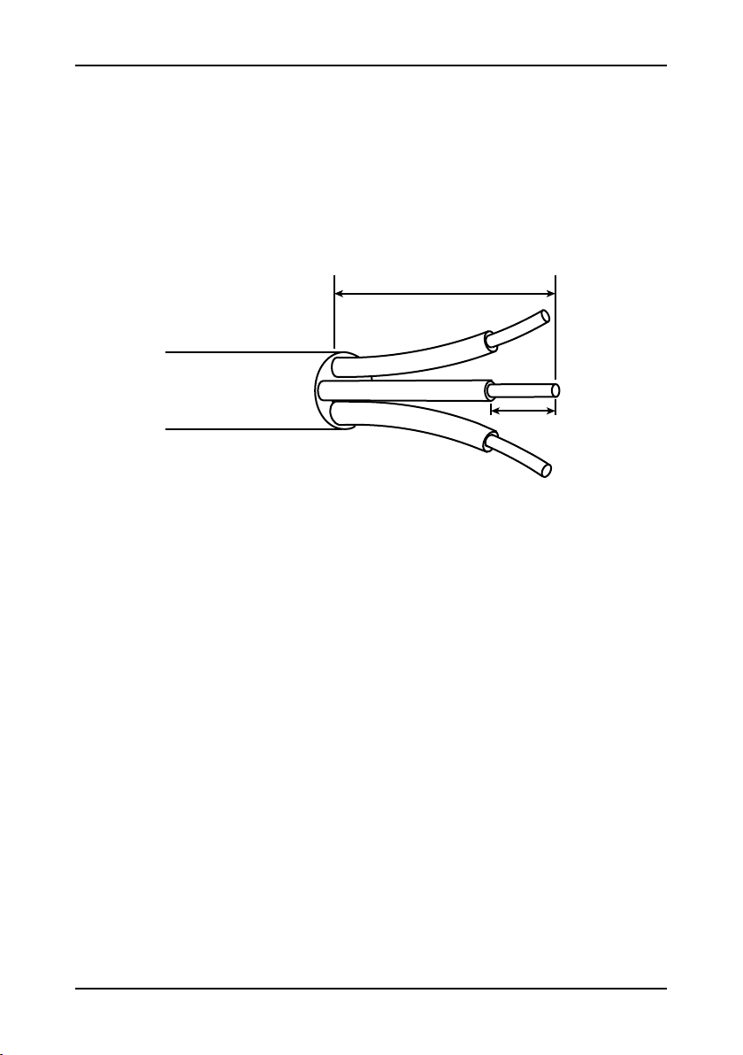
The power cord should be able to provide power continuously at
maximum load for the charging station.
• Power cord thickness: Ø 10 – 22.5 mm.
• Power cord cross-section: solid wires max 10 mm² | string wires
6 mm² .
1,8cm
16cm
1. Strip ±16 cm from the exterior insulating coating of the power cord.
Consider shortening cable length if that makes installation easier.
2. Strip ±1,8 cm from the exterior insulating coating of the N, L3, L2, L1
and PE wires.
4.4. Grounding specifications
The charging station should be grounded in accordance with local
regulations.
4.5. Required nominal input voltage
• 1-phase: 230 V ± 10 % - 50 Hz.
• 3-phase: 400 V (3 × 400 V + N) ± 10 % - 50 Hz.
A 3-phase charging station can also be connected to a 1-phase setup.
Important note: when connecting only 1 phase, the charge point
MUST be connected to L1, NOT to L2 or L3. Make sure there is 230V
between L1 and N at the power input of the charge point.
15

Some electrical vehicles may have a more limited voltage tolerance
than 10%. If issues occur when charging, and the voltage is close to
the 10% voltage tolerance, check that the electrical vehicle type is
suitable for charging with this voltage.
4.6. Electrical protection specifications
Circuit breaker
The installer must select a suitable circuit breaker (type B or C, rated
40A) to match the charging limit of the charging station, taking
into account the specifications of the circuit breaker manufacturer,
selectivity regulations and EV-Ready guidelines.
Set a lower load limit on the charging station than the nominal current
of the charging station protection.
The overcurrent protection is built in
as part of other electrical components
in an existing consumer unit.
Set the load limit to 80%
of the rated current.
The overcurrent protection is built into
a special case with adequate cooling.
A simultaneity factor of 1 was used in
the design of the consumer unit.
Set the load limit to 90%
of the rated current.
Residual current protection
According to IEC 60364-7-722:2015, this charging station must be
installed with a minimum residual current protection type of A, rated
30mA. IEC 60364-7-722:2015, paragraph 722.531.2.101:
Excluding circuits that use electrical isolation as a safety measure,
each connection point shall be shielded using residual current
protection.
Note: When installing in accordance with EV-Ready guidelines,
each residual current protection system must be type A high
immunity: type HPI, SI, HI, KV... depending on the supplier.
RCBO
Has overcurrent and residual current protection as described above.
16

Note: The charging station comes with a DC fault current detection
device, certified in accordance with IEC 62955.
The electrician is responsible for selecting a suitable residual current
protection that complies with local rules and regulations.
5. WALL MOUNTING
Note: For mounting the charger on a pedestal, see the installation
booklet, which is accessible through the QR code or web link
on the first page of this manual.
The wall mounting procedure consists of a few steps.
1. Install the wall bracket.
2. Secure the cable block to the wall bracket.
3. Slide the charger onto the wall bracket.
4. Secure the charger to the wall bracket.
5. Connect the cables.
6. Attach and secure the cover.
7. Attach and secure the socket lid.
8. If necessary, attach a C sticker.
More detailed information about each step is available.
17

Install the wall bracket.
1) The standard installation height is 100 to 110 cm from the floor or
ground, measured from the center of the socket. The wall bracket
contains three pill-shaped clearance holes for installation. Use the
clearance holes to mark the positions on the wall where the holes
should be created, and then drill the three holes.
104-114 cm
Note: Use proper levelling tool to make sure that the wall bracket
is levelled.
Make sure the position of the bracket provides at least 30
centimeters of space around the charger when the charger is
attached to it.
Lead the cables through the circular holes at the bottom of the
bracket. Use either the holes in the back support, or the holes in
the bottom support, as is most convenient for your cable setup.
2) If the mounting surface consists of concrete or brick, fix the
bracket securely to the wall using the provided 3 8mm plugs and
3 M6x30 screws. If there is a different type of mounting surface,
another fixing method must be used.
Note: Make sure the bracket is level and sturdy.
Secure the cable block to the wall bracket.
1) Position the cable block onto the bottom of the wall bracket using
18
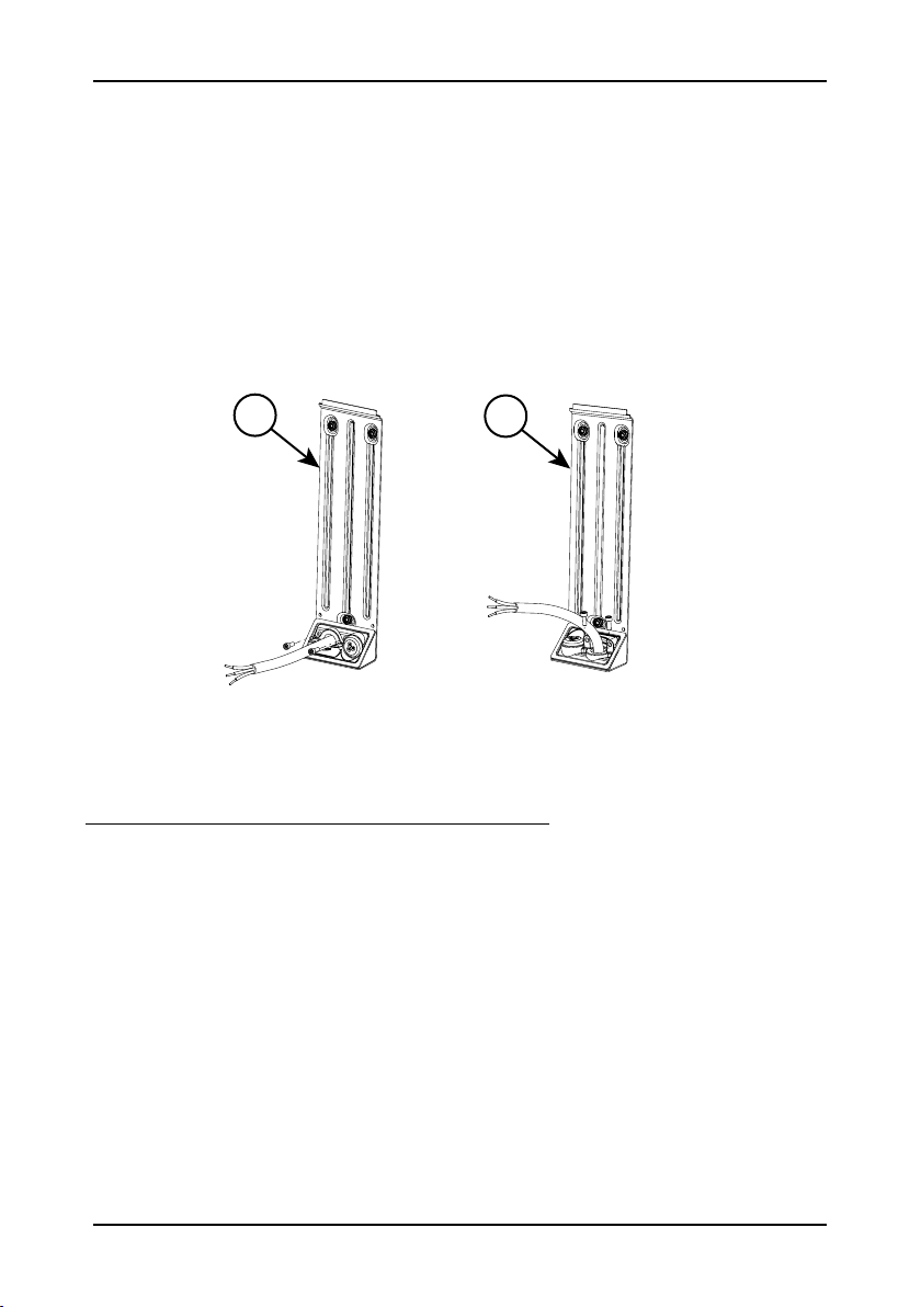
your preferred orientation. There are circular holes in the bottom
and the back of the wall bracket, from which cables can pass
through the cable block into the charger unit. Remove the bridge
component from the cable block. Pull the cables through the
circular holes and through the cable block.
2) Use the provided 2 M5x16 (Torque 1.2Nm) screws to secure
the cable block to the wall bracket. Keep the bridge component
nearby.
12
1: cable from back (wall)
2: cable from below (ground)
Slide the charger onto the wall bracket.
1) Align the niche with the wall bracket.
19

Note: The back of the charger unit contains a niche, designed as
a connection slot for a wall bracket or pedestal bracket.
2) Carefully slide the charger unit onto the wall bracket so that the
wall bracket slots into the back of the charger unit. Lead the
cables into the charger unit through the hole at the bottom.
Secure the charger to the wall bracket.
Use the provided 2 M6x14 (Torque 1.2Nm) screws to secure the
charger unit to the wall bracket through the clearance holes and
tapped holes inside of the mounted charger.
20
Other manuals for Single Wallbox
1
Table of contents
Other eNovates Batteries Charger manuals


