Enovation Controls Murphy PowerView PV485 User manual

00-02-1207
2021-0306-2507
Section 78
PowerView® Display
Model PV485
Murphy Standard Operations Manual

2021-0306-2507 ii 00-02-1207
Please read the following information before installing.
BEFORE BEGINNING INSTALLATION OF THIS MURPHY
PRODUCT:
•Read and follow all installation instructions.
•Please contact Enovation Controls immediately if you have any
questions.
Revision Date
Details
2021-03-25
New Document
2021-06-07
Pre-production revision


2021-0306-2507 iv 00-02-1207
Table of Contents
Introduction...............................................................................................................................76
Engine Parameters....................................................................................................76
Glossary of Terms and Acronyms..............................................................................76
Button Assignments.................................................................................................87
Home Screen.............................................................................................................87
Button Functions........................................................................................................98
Scrolling 12 Gauges.................................................................................................108
Regen Screen..........................................................................................................119
I/O Status Screen.....................................................................................................129
Preset Screen ........................................................................................................1210
Alert Icons..............................................................................................................1311
Popup Message Screen.........................................................................................1412
Main Menu............................................................................................................................ 1512
Enter Password......................................................................................................1613
Display Settings .....................................................................................................1814
Engine Settings......................................................................................................2217
System Settings.....................................................................................................2619
Advanced Settings.................................................................................................3021
IO Settings .............................................................................................................3925
Throttle Settings.....................................................................................................4528
Communication Setup............................................................................................4829
Diagnostics.............................................................................................................5131
Customize Display Interface...................................................................................5533
Main Screen Gauge Setup.....................................................................................5935
Engine Manufacturer Specific Functions................................................................6237
Wiring Instructions..................................................................................................6741
Error! Hyperlink reference not valid.Table of ContentsError! Bookmark not defined.iii
Formatted: Tab stops: 16.83 cm, Right,Leader: …+ Not at
14.17 cm
Formatted: Tab stops: 16.83 cm, Right,Leader: …+ Not at
14.17 cm

2021-0306-2507 v 00-02-1207
Error! Hyperlink reference not valid.Error! Bookmark not defined.Error! Hyperlink reference

2021-0306-2507 vi 00-02-1207
THIS PAGE INTENTIONALLY LEFT BLANK

2021-0306-2507 7 00-02-1207
Introduction
The PV485 is a rugged CAN-based controller. This manual explains the functions and display
screens of the unit, describes the display screens and gives details about the PV485 Murphy
Standard Configuration.
Engine Parameters
The following are some of the 62109 possible engine parameters that can be displayed in
standard or metric units as well as in English, French, German, Spanish, Italian, Japanese,
Chinese, Portuguese, Russian and Czech languages.
•Coolant Level
•Fuel Level
•Alternator Voltage
•Oil Level
•System Voltage
•DEF Level
•Oil Pressure
•Coolant Temperature
•Battery Voltage
•Oil Temperature
•
Glossary of Terms and Acronyms
CAN –Controller Area Network
DM1 –Diagnostic Message 1, Active Diagnostic Trouble Codes
DM2 –Diagnostic Message 2, Previously Active Diagnostic Trouble Codes
DM4 –Freeze Frame Parameters
DPF –Diesel Particulate Filter
DTC –Diagnostic Trouble Code
ECU –Engine Control Unit
FMI –Failure Mode Identifier
PGN –Parameter Group Number
SPN –Suspect Parameter Number
Acronym/Term
Description
CAN
Controller Area Network
DM1
Diagnostic Message 1, Active Diagnostic Trouble Codes
DM2
Diagnostic Message 2, Previously Active Diagnostic Trouble Codes
DM4
Freeze Frame Parameters
DPF
Diesel Particulate Filter
DTC
Diagnostic Trouble Code
ECU
Engine Control Unit
FMI
Failure Mode Identifier
PGN
Parameter Group Number
SPN
Suspect Parameter Number
Formatted: Font: Italic, Font color: Red
Formatted Table
Formatted: Font color: Auto
Formatted: Bulleted + Level: 1 + Aligned at: 0 cm + Tab
after: 0.63 cm + Indent at: 0.63 cm
Formatted: Centered
Formatted Table
Formatted: Font: Bold
Formatted: Font: Bold

2021-0306-2507 8 00-02-1207
Button Assignments
Review the icon on the screen directly above each button to determine that button’s
function. These functions change according to the screen that is displayed. In the above
screen, Button 1 will provide the Password screen to enter the Main Menu. In other screens,
Button 1 will serve a different function.
Home Screen
When first turning on the controller, you will see the Murphy logo display before the Home
screen.
The Home screen displays Engine Hours, Time, RPM/Speed and up to 12 gauges, chosen
from 62available parameters.

2021-0306-2507 9 00-02-1207
Button Functions
The table below explains the button functions when they appear on the screen.
Button Icon
Description
Go to menu password screen.
Throttle or digital gauge value decrease
Throttle or digital gauge value increase
Start engine
Stop engine
Next / Enter
Go to fault screen
Go to preset screen
Go to I/O status screen
Go to regeneration screen
Back
Select previous
Select next
Scrolling 12 Gauges
Pressing the button 5 (or Press and hold for 3 seconds if there are active DM1 faults) on the
main screen (, to reveal the next button hiden button will show up as shown example
in the image screen below) repeatedly will , press button 5 again will to cycle through all 12
chosen digital gauges.

2021-0306-2507 10 00-02-1207
Regen Screen
Pressing button 2 while Regen (as shown in the image
above) is displayed will open the Regen page,
shown below. This provides the user control of engine
regeneration and current DPF status.
This same Regeneration page will automatically
popup when regeneration is required. A User can press Button 3 (FORCE)to
request regeneration or Button 2 (INHIBIT)to prevent/stop regeneration. Press
Button 4 (AUTO)to exit Inhibit mode.
To carry out a force regeneration, each engine’s specific regen requirements must be met.
To carry out a force regeneration, each engine’s specific regen requirements must be met.
I/O Status Screen
Pressing button 4 when IO Status is displayed will
open the I/O status page as shown below.
Display connector pins with their corresponding functions
and current status will be shown. Use button 2 and 4 to scroll through
multiple pages of the IO Status. Once you have navigated to the last available
Commented [TM1]: Would it be better to state it as "In
order to force a regeneration, each engine's specific regen
requirements must be met."
Commented [2R1]: @Trina Moore yes, that’s much
better.

2021-0306-2507 11 00-02-1207
page, the down arrow will turn gray indicating there are no more pages available.
Preset Screen
If Throttle Type is set in the Throttle menu to Preset, the context of main screen
button #2 will change to “PRESET” as shown in the next image.
Once you press the PRESET button, the preset speed options will appear as shownin the
following image. The preset speed allows the user to quickly control engine speed to a pre-
configured target speed. The type of the target speed illustrated below will depend on the
Target RPM Type setting in the menu. Available options are RPM or Percentage.

2021-0306-2507 12 00-02-1207
or
Press the corresponding speed button to request the indicated speed, and the back
button to leave the page.
Alert Icons
The Alert Icons at the top of the main page will light up when communicating to
the operator. Pay close attention to any Status Icon and its color that may appear.
Status Icon
Description
Water in Fuel
Engine Exhaust High Temperature Lamp
Diesel Exhaust Fluid (DEF) Level
Emission failure
Engine Oil Pressure
Preheat –Wait to Start
Check Engine / malfunction
Warning
Diesel Particulate Filter Lamp
Formatted Table

2021-0306-2507 13 00-02-1207
Status Icon
Description
DPF Regeneration set to Inhibit –Displays when the machine or the
operator has inhibited regeneration
Maintenance / Service Required
Check Engine / Protect
Parking Brake Engaged
Transmission Neutral
Stop engine.
Air filter
Fuel filter
Coolant level
Coolant temperature
Inducement warning (FPT only)
Popup Message Screen
When the a popup message is showns screen shows, the user must acknowledge it by
pressing the button 1 to cancel or button 5 to accept, then the popup message screen will
clear. Please pay attention to the indicated messages.

2021-0306-2507 14 00-02-1207
Main Menu
Press (Button 1) then enter the appropriate password to gain access to the Main
Menu.
There are three levels of security for the PV485:
•Low (factory password of 1111)
•Median (factory password of 5311)
•OEM (factory password of 3482)
These password selections may be changed within the menu.
Enter Password
Step
Action
1
Adjust the highlighted number with the –(Button 2) and + (Button 4).

2021-0306-2507 15 00-02-1207
2
Press Button 5 to move to the next number.
3
Repeat steps 1 and 2 to assign all four numbers of the password, then press
Button 3 to confirm.
4
Exit the Menu by pressing Button 1.
When the password has been accepted, the Main Menu screen will appear:
Using Pressing buttons 2 and 4 will scroll through these Main menu items, which will be
described in the following sections:
•Display Settings
•Engine Settings
•System Settings
•Advanced Settings
•I/O Settings
•Throttle Settings
•Communication Setup
•Diagnostics
•Customize Display Interface
•Main Screen Gauge Setup
•Engine special functions (only available to specific engines)
Pressing Button 5 will enter the selected menu area.

2021-0306-2507 16 00-02-1207
Display Settings
The Display Settings menu houses the controls for the appearance of the display:
•Fault Popup
•Day/Night Mode
•Brightness
•Language
•Units
•Clock
•View Service Reminder
Note that each menu item’s current setting is
indicated to the right of the corresponding item. If a Screen Tip is available for the selected
menu item, the
information symbol will be available on the navigation bar. Pressing Button 3 to view the
available Screen Tip for the highlighted Fault popup above will appear as shown below:
Pressing button 3 again will clear the Tip screen.

2021-0306-2507 17 00-02-1207
Fault Popup
This selection allowsthe enabling or disabling of displaying the faults screen pop up. If
disabled, a warning icon will appear on the navigation bar
above button 1 or 5 when an active fault is received. The user must press the
corresponding button to view the fault.
Day / Night Mode
To optimize visibility in Day/Night conditions, the display theme colors will change based on
the selected option mode.
Day Mode
Night Mode
Brightness
This selection controls how dim or bright the screen appears. The changes effect to selected
Day / Night Mode setting.
Language
This selection controls which language appears throughout the displaytheselects the displayed
language. Available languages includinge English, French, German Spanish, Italian,
Japanese, Chinese, Portuguese, Russian or Czech
Units
This selection controls how measurements are displayed.
For Pressure, select between Kpa, Bar or Psi.
For Temperature, select between F or C.
For Speed, select between Mph, Kph or m/s.
For Distance, select between Feet, Meters, mi or Km.
Formatted: Indent: Left: 0 cm

2021-0306-2507 18 00-02-1207
Measurement
Available Selections
Pressure
Kpa, Bar or PSI
Temperature
°F°or °C°
Speed
MPH, KPH or M/S
Distance
Feet, Meters, Mi or Km
Flow
L/s, L/min, gal/min (US) or gal/min (UK)
Volume
L, gal (US) or gal (UK)
Clock
This selection exists allows a user to set the clock and choose a 12- or 24-hour display.
Display Once the clock is set,must c cycle power power on the display to update the clock.
Formatted: Centered
Formatted Table
Formatted: Font: Bold
Formatted: Font: Bold

2021-0306-2507 19 00-02-1207
Step
Action
1
Select Display Settings, then Clock from the Main Menu.
2
The next screen highlights the hour. Adjust this using Buttons 2 and/or 4.
3
To move to the next field, press Button 5.
4
Adjust the minutes. Press Button 5.
5
Select between AM or PM. Press Button 5.
6
(Optional Step) Change between 12HR and 24HR using Buttons 2 or 4.
7
Pressing Button 3 will display popup messages will show ask to confirm or
cancel the new clock settings. set the time and clock settings.
8
Exit the Menu by pressing Button 1.
View Service Reminder
This selection exists to showsdisplays the remaining hours left until service is needed for the
Air filter, Battery life, Belt life, Fuel filter, Oil filter, Oil life and Overhaul. To cChange or reset
the service hours via the Ssystem Ssettings menu.
Engine Settings
The Engine Settings menu houses the settings for the Engine:
•Engine Manufacturer
•Engine Model (optional depends on Engine Manufacture)
•Engine Start Method
•Show Ash Gauge
•Show Soot Gauge
•Show Regen Progress
•Emission Settings

2021-0306-2507 20 00-02-1207
Engine Manufacturer
This selection allows the operator to select the engine manufacturer of the
engine which currently includes: Caterpillar, Cummins, Deutz, JCB", Volvo, Perkins,
HATZ, Yanmar, Kubota, Doosan, Kohler, John Deere, FPT, Isuzu, PSI, Ford, GM and Scania.
By default, the engine manufacturer is set to Other. When an engine
manufacturer is selected the display software will automatically adjust
the required settings to ensure the engine
is controlled per the manufacturer’s requirements.
Engine Model
This optional selection allows the user to select the model of the engine. As with
engine manufacturer, unique settings are applied once a different engine model is
selected to ensure control settings meet the manufacturer’s requirements.
Engine Start Method
This selection allows the operator to select the method that will start the engine:
Engine Start Method
Description
CAN Start
If selected, the engine can be started using a CAN message. The
specific CAN messages need to be programmed.
Digital Output Start
This method uses digital output to control an external relay for
crank.
Key StartDisabled
Crank is controlled by an external device such as a key.
Formatted: Centered
Formatted Table
Formatted: Font: Bold
Formatted: Font: Bold
Other manuals for Murphy PowerView PV485
2
Table of contents
Other Enovation Controls Monitor manuals
Enovation Controls
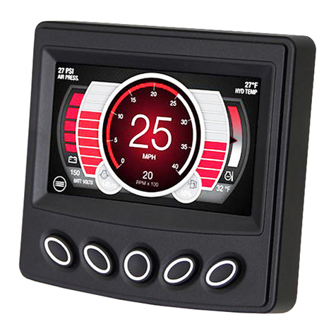
Enovation Controls Murphy PowerView PV485 User manual
Enovation Controls
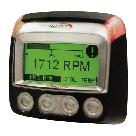
Enovation Controls Murphy PowerView PV101-C User manual
Enovation Controls
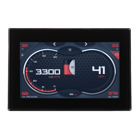
Enovation Controls MURPHY PowerView PV500 User manual
Enovation Controls
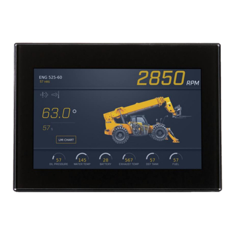
Enovation Controls MURPHY PowerView User manual

Enovation Controls
Enovation Controls Murphy PowerView PV485 User manual
Enovation Controls
Enovation Controls MURPHY PowerView PV1100 User manual
Enovation Controls
Enovation Controls MURPHY PowerView PV380-R3 User manual
