Enovative Technologies DC000A User manual
Enovative Group Inc. www.autohotusa.com Contact: 866-495-2734, [email protected]
DC000A - R9c Draft Installation and Operations Manual
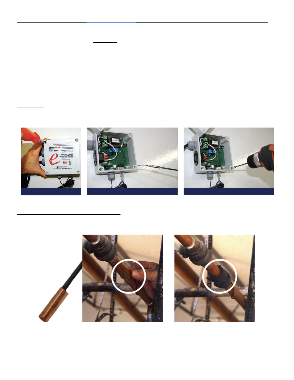
Mount the AutoHot Control Box
AutoHot® can be mounted to a nearby surface using screws. Unscrew lid (avoid power
tools as it may strip the screws). Use the same holes as the lid screws to mount the
box (make sure the wall screw head fits in the hole, and make sure you have a drill but
that is long and skinny enough to go all the way in. Drill into wall.
Important:Make sure the location where you mount the box is reachable for all the
sensors, cables, and power.
Attach the Temperature Sensors
Use the included insulation tape to attach the temperature sensor, concave side
towards the pipe. Zip ties will secure them into place.
R9c 101920 - draft

Enovative Group Inc. www.autohotusa.com Contact: 866-495-2734, [email protected]
The placement of the temperature sensors should be as follows:
T1 -On the return line as far
upstream of the pump as the wire
length and available return line
permit. If there are multiple loops
the sensor needs to be attached on
the side that takes longer to heat
up.
This sensor is important to the
operation of the pump control, as
the lockout temp determines when
the pump should and shouldn’t run.
T2 -This should go on the cold
water pipe, near the top of the tank.
If a boiler system, attach where the
cold water feed tees into the
system, and 6 inches upstream on
the cold pipe.
If a hot water return hits the cold
water inlet, place T2 downstream of
the tee where the return hits,
sensing the mixed temperature
water).
This sensor can send a demand
activation signal to the pump, when
the temperature drops below the
average of the past 10 seconds by
the setting for Temp Drop Trigger
(e.g. 2.5F).
T3 -This should go on the hot out
of the system, right above the
storage tank, but close to the tank.
You want to sense the temperature
of the stored water.
This sensor is used for boiler control
to turn on and off the water heater
based on the target temperature.
(e.g. at 2pm, we only want 112F, so
will keep the water heater off, if
above 112, and turn on if below).
Connect all the components & organize wires
Plug the Flow sensor (if included) into the bottom of the Control Box. Plug the pump into the female power outlet (if your
pump is hardwired, add a power cord). Plug in system to power and finish installation.
R9c 101920 - draft

Enovative Group Inc. www.autohotusa.com Contact: 866-495-2734, [email protected]
Onboard LED status lights -There are LED indicators on the board placed next to the relevant component
to indicate status. See table for list of LED indicators.
LED ID
Location
Description
D3
By Relay 1
On = relay 1 on, which controls pump, meaning pump should be on
D4
By Relay 2
On = relay 2 on, which can control a pump, meaning pump should be on
D14
By Solid State Relay
On = solid state relay on, used to control boiler, meaning the boiler temp sensor is
connected and should fire up to heat up (unless it has hit the boiler temp limit), Off =
the boiler cannot turn on, temp on boiler is disconnected
D12
T1 port
On = T1 is sensing the lockout temp (or within deadband (2-5F)), and it won’t allow
pump on (unless in Timer or constant mode), or will turn off pump. Off = below lockout
temp and can turn on if there is a activation signal or in Thermo mode
D20
T2 port
On = The temp drop activation is activated, therefore temp has fallen on T2 rapidly
D19
T3 port
On = T3 is sensing a temperature at or above the target temperature for this hour of
the day
D13
FLOWSW port
On = there is an activation signal coming from the attached sensor
Make Sure the System is functioning properly
See next page for how to read the LCD and set different settings.
Pump Control -Make sure the T1 led is off, create a activation signal (press BL button, activate flow switch, cause
a temperature drop in T2), and see that the pump turns on (Relay 1 LED turns on), and turns off once Lockout is met (T1
LED turns on).
Boiler Control - Make note of the Boiler setpoint, and turn it up temporarily during testing.
If T3 temperature shown on home screen is below the target temp for the hour of the day shown at the top of the LCD, the
SSR relay LED should be on, and the circle red on the R2 box of the LCD Home Screen and the boiler should be firing.
Within the Boiler Menu on the LCD, turn down the target temp for this hour (shown at top of LCD) to be 5 degrees below
the T3 reading, and the circle should turn black in the R2 box of the Home Screen, and the boiler should stop firing.
Turn the target temperature(Boiler Screen) back up above the T3 reading (Home screen), and the R2 circle should turn
red, and SSR LED turn on, and the boiler should starting firing again. You can turn the target temp up and down to both
turn on and off the boiler to confirm control by the controller. Once satisfied that controller is controlling, set the boiler
setpoint back to where it was.
R9c 101920 - draft

Enovative Group Inc. www.autohotusa.com Contact: 866-495-2734, [email protected]
CONTROLLER OPERATIONS, LCD SETTINGS
Home screen
Screen blinks every second, that's normal.
Large circle - Indicates the connection between the Mainboard and the LCD screen. Should be
green and may indicate an issue if it stays red.
Diamond - Indicates signal strength to a wifi connection, black/empty means no Wi-Fi connection,
and a full symbol (no black) indicates a strong Wi-Fi signal.
Snowman - indicates connection to server. 2 red dots indicate no connection and 2 green dots
indicate the controller is connected and reporting data to the server for display in the web portal.
Date/Time - Date and time
Menu icons
Setup - gives the id, firmware version, WiFi network name, mainboard model, ability to
send and fetch settings between controller and web portal
Pump - pump control settings such as, mode, lockout, Delta, autoprime, interval, tempdrop
trigger
Boiler - settings for boiler profile and boiler control override
T1/R1 - The top right shows the current temperature of T1. The yellow line is a graph of the lockout
temperature setting. The green line represents T1 temperature as a line graph over time. The bottom
red line indicates whether R1 (relay 1, used for return pump actuation) has been running as a line
graph over time. The circle is black if the R1 pump is not currently running and red if the controller is
actuating R1 to turn on the pump meaning the pump is or should be running.
T2/R2 - The top right shows the current temperature of T2. The green line represents T2 temperature
as a line graph over time. The bottom red line indicates whether R2 (relay 2, used for boiler control)
has been running as a line graph over time. The circle is black if the R2 boiler control is at target
temperature and doesn't need to fire up the boiler. The circle is red if the temperature of T3 is below
the target temperature for this hour of the day (or if overwritten) and the boiler should fire up to get to
target temperature.
T3 - The top right shows the current temperature of T3. The green line represents T3 temperature as
a line graph over time.
Note: T1 is for R1/Pump Control. T2 is used for temperature drop pump activation (so its may
activate R1), and T3 controls whether the R2 boiler control wants the boiler to fire up or not.
Setup Screen
Fetch Settings - Hold down the button for fetch settings until the black bar beneath is completely
blue and it will take any settings saved in the web portal, and save them to this controller. This
function also happens every 20 minutes automatically. Only applies to controllers connected to the
web portal.
Send Settings - Hold down the button for send settings until the black bar beneath is completely
blue and it will take the settings currently on the controller and send and save them to the web portal.
If you do not do this while changing settings at the controller, the settings will revert the next time the
controller automatically fetches settings from the server, every 20 minutes. Only applies to controllers
connected to the web portal.
Board model / firmware - displays the mainboard model and firmware version.
ID - displays the ID for this controller.
LCD firmware - displays the firmware version of the LCD
Net - displays the Wi-Fi network name that the controller is trying to connect to. Only applies to
controllers connected to the web portal. Only applies to controllers connected to the web portal.
Pump Settings Screen
To navigate this screen, the work colored in red, indicates the setting that is selected for modification.
Pressing the up and down buttons moves the setting up or down, or left or right. Press the next
button to highlight in red the next setting wished to be changed. The settings only are submitted upon
hitting the back button. If web portal connected, make sure to send the settings to the server so they
do not get automatically overwritten because a web connected controller reads settings from the web
portal every 20 minutes, so you need the local settings sent, in order to sync them up so it doesn't
change.
R9c 101920 - draft

Enovative Group Inc. www.autohotusa.com Contact: 866-495-2734, [email protected]
Mode (default: Demand) - the mode selected in yellow will be the mode select to run. Press the up and down buttons to cycle through the options. See
table below for the meaning of the different modes.
Pump Modes
Demand
This is full demand mode, and most energy efficient. Pump turns on with demand, if lockout temp is not met, and turns off with
lockout temp being met or based on interval time being met.
Thermo
This only looks at meeting the target temp of the lockout. It makes a constant demand signal, so that the pump turns on when T1
has fallen below lockout temp by the deadband (2 to 5 degrees), and turns off once lockout setpoint temperature is met.
Timer
This only looks at the demand (activation) signal, it turns on based on an activation signal, and only turns off after the demand
signal is gone, plus the interval time. Example: flow sensor sensing flow for 10 minutes, and interval set to 60 seconds, the pump
will run for 10 minutes, then an additional 60 seconds, and then turn off.
Constant
This runs the pump 24/7, does not save any energy, but is water efficient and minimizes hot water issues.
Lockout (Default: 115F) - is the target temperature for T1, at which point the the pump is unable to
turn on, or if running, stops running. This only applies to Demand, and Thermo modes, because
constant and timer modes ignore temperature in general.
Delta (Default 6F) - the temperature rise needed on a return line from T1 needed to turn off the
pump. (mostly ignored in commercial/multifamily/houses with return lines)
Autoprime (Default: 10 minutes for commercial, disabled for residential) - Time between
activation pulses, 5 minutes, means it will send a momentary demand signal (activation) every 5
minutes. If T1 is at or above the lockout, this does not mean the pump will turn on.
Interval (Default 5 min) - the amount of time before the pump turns off even if lockout is not met.
E.g. a 5 minute interval means even if T1 is not meeting the lockout, if its run for 5 minutes without an
activation signal it will turn off.
Temp drop trigger (Default 2.5F) - the amount the temperature must drop on T2, when compared to
the average temperature of T2 for the past 10 seconds, for it to send an activation signal which will
be there until the threshold is reached.
Boiler Screen
Screen shows the temperature profile over a 24 hours period, with a different target temperature for
each hour of the day for T3. The selected hour of the day shows as a red marker, and shows in the
bottom left of the screen, while the bottom right shows the target temperature for that hour of the day.
To navigate, press the next button, and it will move to the next hour of the day.
Boiler override - After the 23rd hour, it will show a 24-25th hours (which doesn’t exist), but highlight
the word “Override:” at the top right. Press the up or down buttons to toggle between override off or
on (to override this function).
Target Temperatures - To change any of the target temps, cycle through until the desired hour of the
day is reached (highlighted) and shown at the bottom, and press up and down to change the target
temp for T3.
Once all settings are as desired on this screen, press the back button to save and apply the settings,
at which point they go into affect. For web connected controllers, make sure to send the settings from
the setup menu, to the web portal in order for these settings to not get overwritten the next time it
checks and download the portal settings (every 20 minutes).
Default profile is shown in this table:
R9c 101920 - draft

Enovative Group Inc. www.autohotusa.com Contact: 866-495-2734, [email protected]
AUTOHOTⓇLIMITED WARRANTY
THIS WARRANTY IS APPLICABLE TO THE ORIGINAL OWNER ONLY in accordance with the warranty terms and
conditions specified below.
The warrantor will furnish the ORIGINAL OWNER, 1) a replacement AutoHot of identical model or current equivalent
model if a component inside the AutoHot control box fails and, 2) a replacement part for any external component part
which fails.
THE REPLACEMENT AUTOHOT OR PART WILL BE WARRANTED FOR ONLY THE UNEXPIRED PORTION OF THE
ORIGINAL WARRANTY. The warranty period will be determined by the original date of purchase of the AutoHot, or in the
absence of a Bill of Sale verifying said date, from the date of manufacture indicated on the rating plate affixed to the
AutoHot enclosure. This warranty is not transferable and applies to models listed below:
ITEM
WARRANTY PERIOD
Controller (the control box only, not anything attached to it)
5 years
Pumps (pumps included with the AutoHot)
18 months or OEM warranty
length, whichever is greater
Activators/Accessories (activators and accessories included with AutoHot, or sold by
Enovative Group, Inc.)
1 year
CONDITIONS AND EXCEPTIONS
This warranty shall apply only when the AutoHot is installed and
operated in accordance with 1) all local fire codes, electrical codes,
and plumbing codes, or other ordinances and regulations, 2) the
printed instructions provided with it, 3) good industry practices, and 4)
proper safety practices.
This warranty shall apply only when the AutoHot is:
● owned by the original purchaser;
● installed for indoor operation only, or if installed for outdoor
operation, installed correctly;
● used in a non-corrosive and non-contaminated atmosphere;
● used with factory approved accessories installed;
● in its original installation location;
● in the United States, its territories or possessions, and
Canada;
● Has relays sized in accordance with proper sizing techniques
for the controlled pump;
● bearing a rating plate which has not been altered, defaced or
removed except as required by the warrantor;
● installed with no attempted, nor actual modification or
alteration of the AutoHot’s design in any way, including but
not limited to, the attachment of non-company approved
appliances or equipment, including any additional
aftermarket equipment introduced into the control,
monitoring, or electrical pathways.
Any accident to the AutoHot or any part thereof (including
freezing, fire, floods, or lightning), any misuse, abuse or
alteration of it, any operation of it in a modified form, or any
damage caused by attempts to repair the AutoHot will void
this warranty.This warranty does not apply to a Commercial
AutoHot used in a residential setting, nor does it cover a
Residential AutoHot used in a Commercial Setting, without
prior written approval from warrantor.
This warranty gives you specific legal rights, and you may
have other rights which vary under the laws of each state. If
any provision of this warranty is prohibited or invalid under
applicable state law, that provision shall be ineffective to the
extent of the prohibition or invalidity without invalidating the
remainder of the affected provision or the other provisions of
this warranty.
SERVICE AND LABOR RESPONSIBILITY
UNDER THIS LIMITED WARRANTY, THE WARRANTOR WILL
PROVIDE ONLY A REPLACEMENT AUTOHOT OR PART THEREOF.
THE OWNER IS RESPONSIBLE FOR ALL OTHER COSTS. Such
costs may include but are not limited to:
A. Labor charges for service, removal, or reinstallation of
AutoHot or part thereof.
R9c 101920 - draft

Enovative Group Inc. www.autohotusa.com Contact: 866-495-2734, [email protected]
B. Shipping and delivery charges for forwarding the AutoHot or
replacement part from the nearest distributor and returning
the claimed defective AutoHot or part to such distributor.
C. All costs necessary or incidental for handling and
administrative charges, and for any materials and/or permits
required for installation of the replacement AutoHot or part.
LIMITATION ON IMPLIED WARRANTIES
Implied warranties, including any warranty of merchantability imposed
on the sale of this AutoHot under state law are limited to one year
duration for the heater or any of its parts. Some states do not allow
limitations on how long an implied warranty lasts, so the above
limitations may not apply to you.
CLAIM PROCEDURE
Any claim under this warranty should be initiated with the dealer who
sold the AutoHot, or with any other dealer handling the warrantor’s
products. If this is not practical, the owner should contact: Enovative
Group, Inc., 340 S Lemon Ave Suite 5425, Walnut, CA 91789. Phone:
1.866.495.2734 or visit our website: www.autohotusa.com.
Replacement Parts may be ordered through authorized servicers or
distributors. Refer to your local Yellow Pages for where to call or
contact AutoHot Parts Fulfillment, 340 S Lemon Ave Suite 5425,
Walnut, CA 91789. Phone: 1.866.495.2734 or visit our website:
www.autohotusa.com.
The warrantor will only honor replacement with identical or similar
AutoHot or parts thereof which are manufactured or distributed by the
warrantor.
Dealer replacements are made subject to in-warranty validation by
warrantor.
PROOF OF PURCHASE AND PROOF OF INSTALLATION DATE ARE
REQUIRED TO SUPPORT WARRANTY CLAIM FROM ORIGINAL
OWNER. THIS FORM DOES NOT CONSTITUTE PROOF OF
PURCHASE OR PROOF OF INSTALLATION.
DISCLAIMERS
NO EXPRESSED WARRANTY HAS BEEN OR WILL BE MADE ON
BEHALF OF THE WARRANTOR WITH RESPECT TO THE
MERCHANTABILITY OF THE HEATER OR THE INSTALLATION,
OPERATION, REPAIR OR REPLACEMENT OF THE HEATER OR
PARTS. THE WARRANTOR SHALL NOT BE RESPONSIBLE FOR
WATER DAMAGE, LOSS OF USE OF THE UNIT, INCONVENIENCE,
LOSS OR DAMAGE TO PERSONAL PROPERTY, OR OTHER
CONSEQUENTIAL DAMAGE. THE WARRANTOR SHALL NOT BE
LIABLE BY VIRTUE OF THIS WARRANTY OR OTHERWISE FOR
DAMAGE TO ANY PERSONS OR PROPERTY, WHETHER DIRECT
OR INDIRECT, AND WHETHER ARISING IN CONTRACT OR IN
TORT.
Should governmental regulations or industry standards prohibit the
Manufacturer from furnishing a comparable model replacement under
this warranty, the Owner will be furnished with the closest comparable
model meeting the then current governmental regulations and industry
standards. A supplementary fee may be assessed to cover the
additional cost associated with the changes made to meet applicable
regulations and standards.
IMPORTANT INFORMATION
Model Number
Serial Number
Date Installed
Installer Company Name
Installer Address
Installer Phone Number
Installer License Number
Recirculation Pump Model
Recirculation Pump Serial Number
Water Heater Model
Water Heater Serial Number
R9c 101920 - draft
Table of contents


