Warnings
•Keep the operation zone free. Consider it a security zone. This zone will
be free of persons and objects that could be an obstacle by shifting the
machine or moving any of its parts. Take care that the raising elements
do not encounter an obstacle in their way.
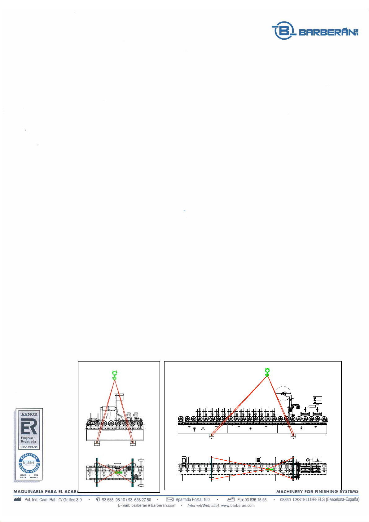
•Before lifting the machine you have to equilibrate its weight (see
technical feature sheet) and use the adequate equipment to raise it.
•All the operations that are mentioned in this section should be done by
personnel authorized for this tasks.
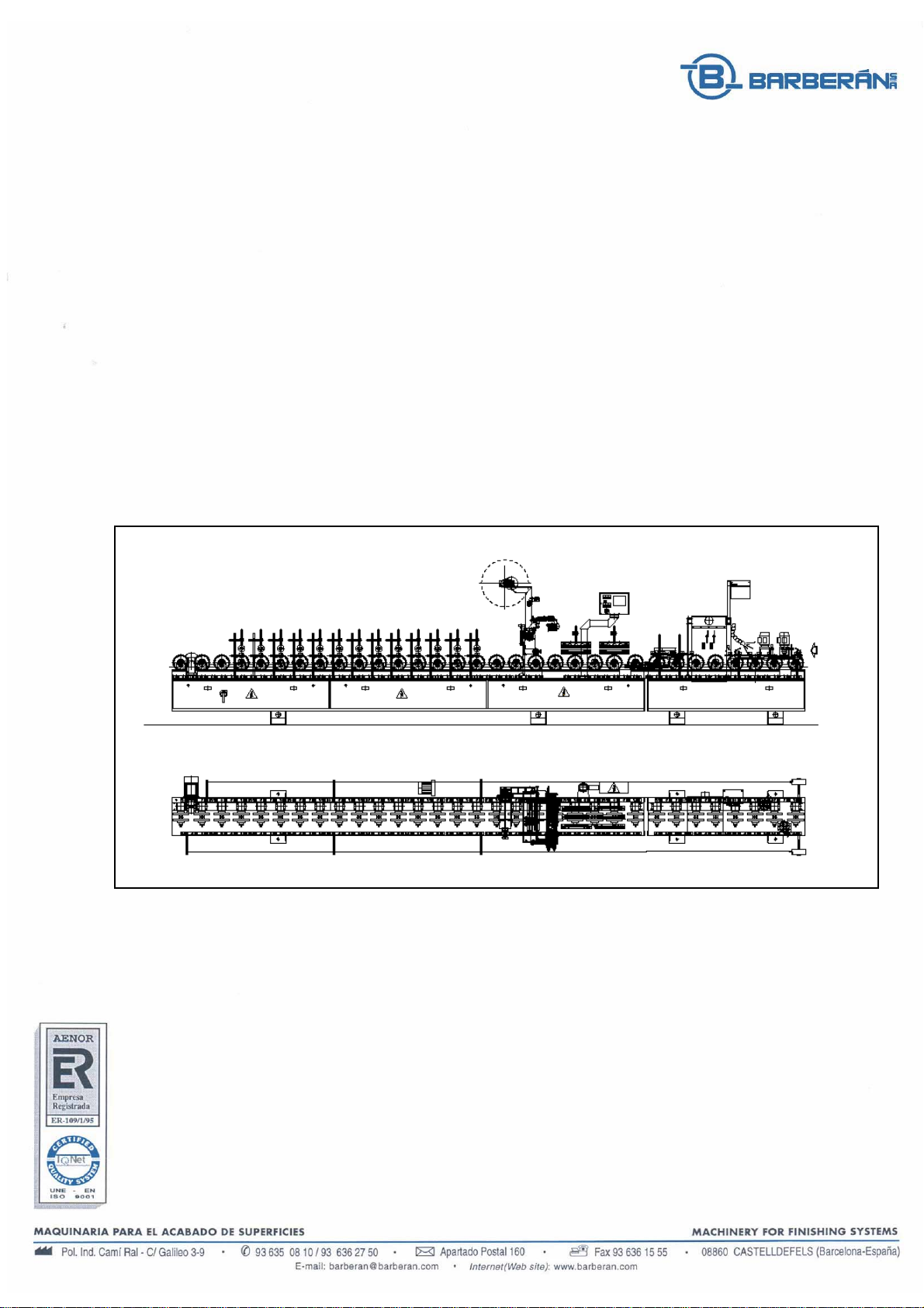
1.3.3 Positioning and installation
The positioning of the machine must be done in a place which has all
necessary conditions like status of the floor, leveling, good lighting, ventilation
and air exhaustion and weather protected.
The machine must have enough free space at both sides to allow an
easy access for operation. The minimum area to be considered should be 2
meters at the control side and 1 meter at the opposite side. Do not place any
material or obstacles in these areas.
Warning
•Consider to use protection cover for wirings and pipes on the floor to
avoid falls of the personnel.
1.3.3.1 Positioning conditions
The machine must be levelled in the perpendicular direction to the floor,
using the levelling screws placed at the bedframe base. If the machine is part of
a line, you have to level the machine according to the line level, that means so
that the working height coincides with the prior and next machine. As a
reference, please use the conveyor.
1.3.3.2 Electric connections
Before the machine is connected, you must verify that the network
connection complies with the present standards.
Verify that the tensión and frecuency are the ones indicated in the
identification plate of the machine. If this data does not coincide, please do not
proceed with the connection.