AESSEAL FDU Plan 54 Manual

YDR-FDU-PLAN54-08 06/17
FDU™ Plan 54
Installation Operations & Maintenance Instructions

YDR-FDU-PLAN54-08 06/17
AESSEAL plc, Complex Systems Division, Mill Close, Bradmarsh Business Park, Rotherham, S60 1BZ
Tel: +44 (0) 1709 369966 Fax: +44 (0) 1709 720788 www.aesseal.com
Page 2 of 6
Health and Safety
● This system has been designed for use only as a barrier fluid system for mechanical seals using a suitable
non-hazardous barrier fluid.
● Isolate the process and power on installation, maintenance and decommissioning and ensure that the
system pressure has been relieved before undertaking maintenance
● The system should only be installed by competent engineering personnel.
● Electrical connections must be made in compliance with applicable legislation and / or local requirements by
a competent / qualified electrician.
● Pipe relief valves discharge to safe area (when fitted).
● Run a leak test of the complete system assembly at maximum working pressure (duration 5 minutes) and
ensure the system is completely leak free before putting into service.
● Do not exceed the operating limits of the system. Not designed for cyclic loading.
● The system may get hot in operation with risk of burn injury, and suitable engineering controls or guarding
should be adopted where necessary. The risk from Legionella bacteria should be assessed with water
barrier fluids at temperatures between 20°C to 45°C (68°F to 115°F).
● If the barrier fluid becomes contaminated it is recommended that the barrier fluid is replaced taking necessary
precautions. If the contamination is potentially corrosive or damaging to the system, remove from service
and contact AESSEAL for technical advice.
Environment
Once the barrier fluid and system have reached the end of its life, it should be disposed of in accordance with local regulations
and with due regard to the environment.
For further information please contact AESSEAL®

YDR-FDU-PLAN54-08 06/17
AESSEAL plc, Complex Systems Division, Mill Close, Bradmarsh Business Park, Rotherham, S60 1BZ
Tel: +44 (0) 1709 369966 Fax: +44 (0) 1709 720788 www.aesseal.com
Page 3 of 6
Installing & Commissioning
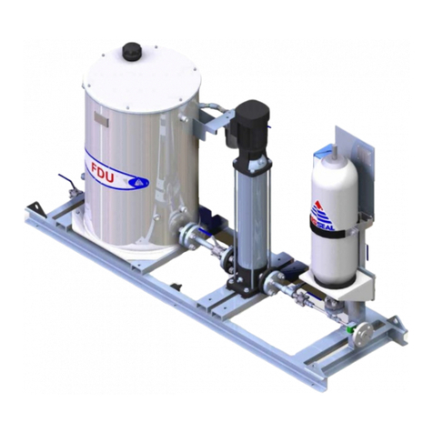
Typical FDU Plan 54 with Options
Fig.1a Typical layout
Fig.1b Typical layout
Please also refer to the drawing contained in the document pack whilst reading these instructions!

YDR-FDU-PLAN54-08 06/17
AESSEAL plc, Complex Systems Division, Mill Close, Bradmarsh Business Park, Rotherham, S60 1BZ
Tel: +44 (0) 1709 369966 Fax: +44 (0) 1709 720788 www.aesseal.com
Page 4 of 6
Fig. 2 Typical P&ID Configurations
Fig.2
Installing & Commissioning
Connections
Ensure all connections are made:
AWater supply
BTank drain
CSeal supply
DSeal return
EOverflow
FSpare connection
● The FDU can be situated on any convenient flat and level surface (such as a concrete floor or plinth), within
close proximity of the seals and support systems.
● Ensure the system is securely affixed to the floor using correct sized bolts inserted through the holes in the
FDU mounting skid.
● Pipe runs may be in hard pipe or suitable flexible hoses, 1” or greater pipe bore is recommended.
● The pipe run should be suitably supported and secured, avoiding potential hazards, such as steam pipes,
walkways etc.
● Check that the pipe runs are connected from inlet and outlet connections to and from the seal support
systems. Ensure that all threaded and compression fittings are tightened. Ensure that all seal supply lines are
fully vented.
● Check that the pipe run is connected to the tank water supply.
● Ensure electrical connections are made to the centrifugal pump/motor set, and ensure correct direction.
● Ensure that any isolation valves between the seal system and the seal (if fitted) are open, and all vents and
drains are closed.
● Ensure that any back pressure control valves (if fitted), are fully open, and all vents and drains are closed.
● Ensure any isolation valves fitted to the pressure gauge are open.
● Fill the tank with fresh clean barrier fluid via the filler breather or via inlet fill ball valve to 50mm / 2” below the
overflow and pay careful attention to the level of the fluid when priming the circuit to ensure the pump does
not run dry. N.B. It may be necessary to stop/start the pump to prime the system fully.

YDR-FDU-PLAN54-08 06/17
AESSEAL plc, Complex Systems Division, Mill Close, Bradmarsh Business Park, Rotherham, S60 1BZ
Tel: +44 (0) 1709 369966 Fax: +44 (0) 1709 720788 www.aesseal.com
Page 5 of 6
● Consult Grundfoss pump/motor manual for instructions on how to prime the pump; once the pump has been
primed it may now be started.
Nb. DO NOT start the pump until it has been filled with liquid and vented. Check rotation of motor by means
of the motor fan and label on top of the fan cover.
● Adjust the pressure by adjusting the selected systems pressure control valve, or other, until desired working
settings are reached.
● Ensure the desired pressure is reached by checking the pressure gauge/switch read out.
● Consult Grundfoss instruction manual for any pump/motor technical information.
Operation
● The 180 litre FDU arrangement requires little attention in operation, however the following should be
observed:
● The condition of the barrier fluid and suction filter must be checked after one week following commissioning
or any major maintenance such as a seal change. If satisfactory, further checks should be carried out at
monthly intervals.
● The fill point of the system is connection A on Fig.2 via the ball valve fitted at the top of the tank. The drain
point is connection B on Fig.2 which is also via a ball valve fitted at the base of the tank.
For system specifications and design limits, please see drawing.
Noise Emission Declaration
● In accordance with BS EN ISO 20361:2009 (Grade 2) and BS EN ISO 3744 the A-weighted emission sound
pressure level, LpA, does not exceed 70 dB (A). The noise measurements were taken at a distance of 1
metre from the surface of the system at a height of 1.6 metres from the floor and measurement uncertainty is
2.5 dBA.
Maintenance
The system should be maintained in accordance with site standards, or local regulations.
Daily
● Check and record the system pressure reading, any change may be a sign of a developing problem, such as
a blockage/advanced seal leakage.
● Check for signs of leakage from seal, system, and pipe work.
● Check water level, water supply and temperature.
● Check any alarms on the pressure and level switches or transmitters if fitted.
Monthly
● Any filters (If fitted), should be inspected every month and changed if contaminated/blocked.
● Any discolouration of the barrier fluid or contamination of the filter may be an indication of leakage of the
inboard mechanical seal, and should be investigated immediately.

YDR-FDU-PLAN54-08 06/17
AESSEAL plc, Complex Systems Division, Mill Close, Bradmarsh Business Park, Rotherham, S60 1BZ
Tel: +44 (0) 1709 369966 Fax: +44 (0) 1709 720788 www.aesseal.com
Page 6 of 6
Optional Extras
Air Blast Cooler
● If an Air Blast Cooler has been fitted, make sure that the fan and motor are rotating in the correct direction.
Twin Pumps
● The secondary pump/motor combination can be used as a back-up if first pump/motor failure occurs, or to
perform any maintenance or servicing.
Freeze Fuse Settings
● The Freeze Fuse has a rotating dial which adjusts the temperature at which the valve opens to allow colder
water to be relieved to a suitable drain point. The standard temperature range is between 0 and 30 degrees
C. Adjust the rotating dial to the desired temperature.
External Filter
● Visually inspect the filter through the viewing widow to determine any contaminant build up, and replace filter
cartridge if deemed necessary.
Pressure & Level Transmitters
● Adjust the pressure and level transmitter until desired working settings are reached, consult manufacturers
operating manuals for any technical information.
Float Valve
● Adjust until required level is reached, consult manufacturers operating manual for any technical information.
Finned Tubing
● Install the supplied lengths of finned tubing by connecting one length to the seal supply connection, and the
other to the seal return connection on the system.
● The end user will supply and connect the hard pipe from the seal to the finned tubing.
Multiple seals option
● It is an option for the water supply from the pump to be split to provide flow to 2 or more seals. This is
generally achieved by fitting flow orifice plates in the feed line to each seal. The return line to the tank will be
fitted with the correct number of back pressure valves, which will ensure that the pressure is maintained to
each seal.
● Nb. Extra care should be taken during installation, commissioning, and decommissioning of the FDU to
ensure control to the seal is constantly maintained. For further information, please contact your local
AESSEAL representative.
Cooler And Plate Heat Exchangers
● If a Cooler or Plate Heat Exchanger is supplied with the system then please use the installation instructions
provided from the manufacturer.
● Check for any leaks on the cooler, connections and pipe work and rectify before continuing.
● Allow the system to stabilise and warm-up, checking that pressures remain stable and that no leaks appear.
● If you have purchased an optional extra please refer to the installation instructions supplied by the
manufacturer.
Table of contents
Other AESSEAL Industrial Equipment manuals
Popular Industrial Equipment manuals by other brands
Frick
Frick Vyper 700 Installation operation & maintenance
Palax
Palax DECK 2.0 user manual
CommScope
CommScope DryLine ODPMT200 Series user manual
Danfoss
Danfoss IPS 8 Technical data, installation and use

ITW
ITW Simco Ion Conveyostat Installation and operating instructions
General
General 840 Instructions for use
AAF
AAF RotoClone LVN Installation, operation and maintenance manual
Heatcraft
Heatcraft POLARPACK Handbook
Goudsmit
Goudsmit Easy Clean Cleanflow SECE Series user manual
ABB
ABB HT567640 Operation manual

Workhorse Products
Workhorse Products Wash-It owner's manual

Titan
Titan 519 Installation, Maintenance, and Parts Manual
